EP0680902A1 - Container docking device at a discharging bin for the pharmaceutical industry - Google Patents
Container docking device at a discharging bin for the pharmaceutical industry Download PDFInfo
- Publication number
- EP0680902A1 EP0680902A1 EP95102079A EP95102079A EP0680902A1 EP 0680902 A1 EP0680902 A1 EP 0680902A1 EP 95102079 A EP95102079 A EP 95102079A EP 95102079 A EP95102079 A EP 95102079A EP 0680902 A1 EP0680902 A1 EP 0680902A1
- Authority
- EP
- European Patent Office
- Prior art keywords
- container
- underside
- flap
- funnel
- sleeve
- Prior art date
- Legal status (The legal status is an assumption and is not a legal conclusion. Google has not performed a legal analysis and makes no representation as to the accuracy of the status listed.)
- Granted
Links
Images
Classifications
-
- B—PERFORMING OPERATIONS; TRANSPORTING
- B65—CONVEYING; PACKING; STORING; HANDLING THIN OR FILAMENTARY MATERIAL
- B65G—TRANSPORT OR STORAGE DEVICES, e.g. CONVEYORS FOR LOADING OR TIPPING, SHOP CONVEYOR SYSTEMS OR PNEUMATIC TUBE CONVEYORS
- B65G69/00—Auxiliary measures taken, or devices used, in connection with loading or unloading
- B65G69/18—Preventing escape of dust
- B65G69/181—Preventing escape of dust by means of sealed systems
- B65G69/183—Preventing escape of dust by means of sealed systems with co-operating closure members on each of the parts of a separable transfer channel
Definitions
- the invention relates to a device for docking a container equipped with an outlet opening according to the preamble of the main claim.
- the transfer of powdered or dusty substances from one container to another container is often necessary, the one container being in a bacteria-free and germ-free room, while the other container is in the normal ambient atmosphere. It is necessary here that the powdery or dusty substances are not only transferred dust-free from the first to the second device, but it is also necessary that no germs can enter the receiving device during the transfer. In pharmaceutical companies where the highest level of cleanliness, if not sterility, is required, it is also necessary that there are no adhering germs or the like on the underside of the container moved in the normal ambient atmosphere. In the generic device, germs can still enter the transfer device to be loaded when the container is attached to the sleeve.
- the invention has for its object to provide a device in which it is ensured that when docking two devices, for example a container moving in the ambient atmosphere to a discharge funnel standing in a sterile environment, the entry of germs through the underside of the container into the discharge funnel is excluded becomes.
- the container moving in the normal ambient air on its underside ie the side with which it comes into contact with the inside of the discharge funnel to be connected to it, is protected as long as a transfer of the content of the Containers in the emptying funnel is not necessary.
- a flap protection is proposed, which can be placed on the underside of the container and which is pulled off from the underside of the container, for example by a vacuum suction device in the area of the emptying funnel, so that this germ-free underside of the container is then placed on the sleeve inserted between the container and emptying funnel can be. In this way, an almost sterile transfer of the container contents into the emptying funnel is achieved.
- a protective cover is further proposed according to the invention, which is combined with the vacuum suction device in such a way that - when the filling opening of the emptying funnel is not used - the latter Protective cover can be placed on the upper side of the cuff.
- the protective cover is lifted off at the same time, so that two important jobs which ensure the sterility of the goods to be transferred can be carried out in one operation.
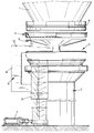
- the drawing shows the part of a container 1 in which the emptying opening known per se cannot be seen, but the lower edge of this container has a constriction 8 in the outer region.
- a flap protection 4 which consists of a cup-shaped component that can be placed over the underside of the container 1, in which case provided on the upper edge of the flap protection 4 provided inwardly projecting inner lugs 10 into the constrictions 8 of the container and thereby hold the flap guard 4 in place.
- the flap guard 4 can be placed on the underside of the container 1 via a lifting device 6, on the top of which a vacuum suction device 5 is arranged, on which the flap guard 4 rests. If this lifting device 6 is actuated, the flap protection 4 resting on the vacuum suction device 5 is connected to the underside of the container.
- a support device 9 which in the illustrated embodiment has an upper horizontal arm 12 and a vertical arm 14, so that it is possible that this support device 9 in the space between the underside of the container 1 and the top of the Cuff 3 can intervene.
- the cuff 3 consists of an upper section and a lower section, the upper section being relatively rigid, i. H. the wall of the upper section cannot carry out any radially directed movements, the transition between the lower and the upper section being designed in such a way that there is a configuration which causes the flexibility of the sleeve 3, i. H. when docking, the upper section of the sleeve 3 can move somewhat into the lower section of the sleeve 3, so that the required contact pressure of the upper edge of the sleeve 3 against the underside of the container 1 is thereby achieved.
- the lifting device 6 for the vacuum suction device 5 is coupled to a swiveling device 7, so that when the swiveling device 7 is actuated, the upper horizontal arm 12 of the support device 9 which adjoins the lifting device 6 and carries the vacuum suction device 5, so that the vacuum suction device 5, the protective cover 11 and the flap protection 4 can be moved from the connection area between the lower edge of the container 1 and the upper edge of the sleeve 3.
- the vacuum suction device 5 is turned on brought the underside of the flap guard 4 into contact and placed the inside of the vacuum suction device 5 under vacuum, so that the flap protection device 4 adheres firmly to the vacuum suction device 5. If the vacuum suction device 5 is now moved downwards via the lifting device 6, the flap guard 4 is pulled off the container 1 and can be moved out of the connection area between the container 1 and the emptying funnel 2 by actuating the pivoting device 7, so that the container 1 is then on the upper edge of the Cuff 3 can be put on.
- the upper horizontal arm 12 of the support device 9 carries on its underside a protective cover 11 which is dimensioned in its outer diameter such that it can overlap the upper section of the sleeve 3. By lowering the carrying device 9, the upper open opening can then be closed by the protective cover 11 when the emptying funnel 2 is not required.
Landscapes
- Engineering & Computer Science (AREA)
- Mechanical Engineering (AREA)
- Basic Packing Technique (AREA)
- Control And Other Processes For Unpacking Of Materials (AREA)
Abstract
Description
Die Erfindung bezieht sich auf eine Vorrichtung zum Andocken eines mit einer Auslaßöffnung ausgerüsteten Containers gemäß dem Oberbegriff des Hauptanspruches.The invention relates to a device for docking a container equipped with an outlet opening according to the preamble of the main claim.
Eine Einrichtung der gattungsbildenden Art wird in der DE-38 16 507 C1 beschrieben.A device of the generic type is described in DE-38 16 507 C1.
In der pharmazeutischen Industrie ist häufig die Übergabe pulver- oder staubförmiger Stoffe aus einem Behälter in einen anderen Behälter erforderlich, wobei sich der eine Behälter in einem bakterien- und keimfreien Raum befindet, während der andere Behälter sich in der normalen Umgebungsatmosphäre aufhält. Hierbei ist es erforderlich, daß die pulver- oder staubförmigen Stoffe nicht nur staubfrei von der ersten in die zweite Einrichtung übergeben werden, sondern es ist weiterhin erforderlich, daß während der Übergabe keine Keime in die aufnehmende Einrichtung eintreten können. In pharmazeutischen Betrieben, in denen höchste Sauberkeit, wenn nicht sogar Sterilität, gefordert wird, ist es außerdem erforderlich, daß an der Unterseite des in der normalen Umgebungsatmosphäre bewegten Behälters keine anhaftenden Keime oder dergleichen vorhanden sind. Bei der gattungsbildenden Einrichtung kann beim Ansetzen des Behälters an die Manschette immer noch ein Eindringen von Keimen in die zu beschickende Übergabevorrichtung eintreten.In the pharmaceutical industry, the transfer of powdered or dusty substances from one container to another container is often necessary, the one container being in a bacteria-free and germ-free room, while the other container is in the normal ambient atmosphere. It is necessary here that the powdery or dusty substances are not only transferred dust-free from the first to the second device, but it is also necessary that no germs can enter the receiving device during the transfer. In pharmaceutical companies where the highest level of cleanliness, if not sterility, is required, it is also necessary that there are no adhering germs or the like on the underside of the container moved in the normal ambient atmosphere. In the generic device, germs can still enter the transfer device to be loaded when the container is attached to the sleeve.
Der Erfindung liegt die Aufgabe zugrunde, eine Vorrichtung zu schaffen, bei der sichergestellt ist, daß beim Andocken zweier Einrichtungen, beispielsweise eines in der Umgebungsatmosphäre bewegten Behälters an einen in steriler Umgebung stehenden Entleerungstrichter das Eintragen von Keimen durch die Unterseite des Behälters in den Entleerungstrichter ausgeschlossen wird.The invention has for its object to provide a device in which it is ensured that when docking two devices, for example a container moving in the ambient atmosphere to a discharge funnel standing in a sterile environment, the entry of germs through the underside of the container into the discharge funnel is excluded becomes.
Diese der Erfindung zugrundeliegende Aufgabe wird durch die Lehre des Hauptanspruches gelöst.This object on which the invention is based is achieved by the teaching of the main claim.
Vorteilhafte Ausgestaltungen sind in den Unteransprüchen erläutert.Advantageous configurations are explained in the subclaims.
Mit anderen Worten ausgedrückt, wird vorgeschlagen, daß der sich in der normalen Umgebungsluft bewegende Container an seiner Unterseite, d. h. der Seite, mit der er mit dem Inneren des an ihn anzuschließenden Entleerungstrichters in Kontakt kommt, solange geschützt ist, wie eine Übergabe des Inhalts des Containers in den Entleerungstrichter nicht notwendig ist. Hierzu wird ein Klappenschutz vorgeschlagen, der auf die Unterseite des Containers aufgesetzt werden kann und der beispielsweise durch einen Vakuumsauger im Bereich des Entleerungstrichters von der Unterseite des Containers abgezogen wird, so daß dann diese keimfreie Unterseite des Containers auf die zwischen Container und Entleerungstrichter eingeschaltete Manschette aufgesetzt werden kann. Hierdurch wird eine nahezu sterile Übergabe des Containerinhaltes in den Entleerungstrichter erreicht.In other words, it is proposed that the container moving in the normal ambient air on its underside, ie the side with which it comes into contact with the inside of the discharge funnel to be connected to it, is protected as long as a transfer of the content of the Containers in the emptying funnel is not necessary. For this purpose, a flap protection is proposed, which can be placed on the underside of the container and which is pulled off from the underside of the container, for example by a vacuum suction device in the area of the emptying funnel, so that this germ-free underside of the container is then placed on the sleeve inserted between the container and emptying funnel can be. In this way, an almost sterile transfer of the container contents into the emptying funnel is achieved.
Um auch die nach außen hin offene Seite des Entleerungstrichters bzw. der auf diesem Entleerungstrichter angeordneten Manschette zu schützen, wird weiterhin gemäß der Erfindung ein Schutzdeckel vorgeschlagen, der so mit dem Vakuumsauger kombiniert ist, daß - wenn die Einfüllöffnung des Entleerungstrichters nicht benutzt wird - dieser Schutzdeckel auf die obere Seite der Manschette aufgesetzt werden kann. Beim Anlegen der Oberseite des Vakuumsaugers an die Unterseite des Klappenschutzes wird gleichzeitig der Schutzdeckel mit abgehoben, so daß in einem Arbeitsgang zwei wichtige und die Sterilität des übergebenden Gutes sicherstellende Arbeiten durchgeführt werden können.In order to protect the outwardly open side of the emptying funnel or the sleeve arranged on this emptying funnel, a protective cover is further proposed according to the invention, which is combined with the vacuum suction device in such a way that - when the filling opening of the emptying funnel is not used - the latter Protective cover can be placed on the upper side of the cuff. When the top of the vacuum suction device is placed on the underside of the flap guard, the protective cover is lifted off at the same time, so that two important jobs which ensure the sterility of the goods to be transferred can be carried out in one operation.
Ein Ausführungsbeispiel der Erfindung wird nachfolgend anhand der Zeichnung erläutert.An embodiment of the invention is explained below with reference to the drawing.
In der Zeichnung ist der Teil eines Containers 1 gezeichnet, bei welchem die an sich bekannte Entleerungsöffnung nicht zu erkennen ist, wobei aber der untere Rand dieses Containers im äußeren Bereich eine Einschnürung 8 aufweist.The drawing shows the part of a
Unterhalb des Containers 1 ist ein Klappenschutz 4 dargestellt, der aus einem tassenförmigen Bauteil besteht, daß über die Unterseite des Containers 1 aufgesetzt werden kann, wobei dann an der Oberkante des Klappenschutzes 4 vorgesehene nach innen ragende Innennasen 10 in die Einschnürungen 8 des Containers einrasten und hierdurch den Klappenschutz 4 festhalten. Das Aufsetzen des Klappenschutzes 4 an die Unterseite des Containers 1 kann über eine Hubeinrichtung 6 erfolgen, an deren Oberseite ein Vakuumsauger 5 angeordnet ist, auf dem der Klappenschutz 4 aufruht. Wird diese Hubeinrichtung 6 betätigt, wird der auf dem Vakuumsauger 5 aufruhende Klappenschutz 4 an die Unterseite des Containers angeschlossen.Below the
An die Hubeinrichtung 6 schließt eine Tragvorrichtung 9 an, die bei dem dargestellten Ausführungsbeispiel einen oberen horizontalen Arm 12 und einen vertikalen Arm 14 aufweist, so daß es möglich ist, daß diese Tragvorrichtung 9 in den Raum zwischen die Unterseite des Containers 1 und die Oberseite der Manschette 3 eingreifen kann.At the
Unterhalb des Containers 1 ist in der Zeichnung ein Entleerungstrichter 2 dargestellt, dessen Oberseite durch eine Manschette 3 abgeschlossen wird, die zum Stand der Technik gehört. Die Manschette 3 besteht aus einem oberen Abschnitt und einem unterem Abschnitt, wobei der obere Abschnitt relativ fest ausgebildet ist, d. h. die Wandung des oberen Abschnittes können keine radial gerichteten Bewegungen ausführen, wobei der Übergang zwischen dem unteren und dem oberen Abschnitt so gestaltet ist, daß hier eine die Nachgiebigkeit der Manschette 3 bewirkende Ausgestaltung liegt, d. h. bei Andocken kann sich der obere Abschnitt der Manschette 3 etwas in den unteren Abschnitt der Manschette 3 hineinbewegen, so daß dadurch der erforderliche Anpreßdruck des oberen Randes der Manschette 3 an die Unterseite des Containers 1 erreicht wird.Below the
Die Hubeinrichtung 6 für den Vakuumsauger 5 ist mit einer Schwenkeinrichtung 7 gekoppelt, so daß bei Betätigen der Schwenkeinrichtung 7 der obere horizontale Arm 12 der an die Hubeinrichtung 6 anschließenden und den Vakuumsauger 5 tragenden Tragvorrichtung 9 verschwenkt werden kann, so daß dadurch der Vakuumsauger 5, der Schutzdeckel 11und der Klappenschutz 4 aus dem Verbindungsbereich zwischen der Unterkante des Containers 1 und der Oberkante der Manschette 3 verbracht werden kann.The
Ist der Klappenschutz 4 in der Einschnürung 8 des Containers 1 verrastet und soll nunmehr dieser Klappenschutz 4 vom Container 1 abgenommen werden, wird der Vakuumsauger 5 an die Unterseite des Klappenschutzes 4 zur Anlage gebracht und das Innere des Vakuumsaugers 5 unter Vakuum gestellt, so daß dadurch der Klappenschutz 4 fest am Vakuumsauger 5 haftet. Wird nunmehr über die Hubvorrichtung 6 der Vakuumsauger 5 nach unten bewegt, wird der Klappenschutz 4 vom Container 1 abgezogen und kann durch betätigen der Schwenkeinrichtung 7 aus dem Verbindungsbereich zwischen Container 1 und Entleerungstrichter 2 verbracht werden, so daß dann der Container 1 auf die Oberkante der Manschette 3 aufgesetzt werden kann.If the
Der obere horizontale Arm 12 der Tragvorrichtung 9 trägt an seiner Unterseite einen Schutzdeckel 11, der in seinem Außendurchmesser so bemessen ist, daß er den oberen Abschnitt der Manschette 3 übergreifen kann. Durch Absenken der Tragvorrichtung 9 kann also dann - wenn der Entleerungstrichter 2 nicht benötigt wird - die obere offene Öffnung durch den Schutzdeckel 11 verschlossen werden.The upper
Hierdurch ist es möglich, den Container 1 an seiner wichtigsten Seite, nämlich der Unterseite, die mit dem Inneren des Entleerungstrichters 2 in Kontakt kommen kann, sicher zu schützen, wobei das Ansetzen dieses sogenannten Klappenschutzes 4 in einfachster Weise durch einfache mechanische Mittel erfolgen kann, wobei gleichzeitig auch die obere Einfüllöffnung des Entleerungstrichters 2 durch den Schutzdeckel 11 geschützt wird.This makes it possible to safely protect the
Claims (7)
gekennzeichnet durch,
characterized by
Applications Claiming Priority (2)
| Application Number | Priority Date | Filing Date | Title |
|---|---|---|---|
| DE4416011 | 1994-05-06 | ||
| DE4416011A DE4416011A1 (en) | 1994-05-06 | 1994-05-06 | Device for docking a container to an emptying funnel in the pharmaceutical industry |
Publications (2)
| Publication Number | Publication Date |
|---|---|
| EP0680902A1 true EP0680902A1 (en) | 1995-11-08 |
| EP0680902B1 EP0680902B1 (en) | 1997-07-23 |
Family
ID=6517465
Family Applications (1)
| Application Number | Title | Priority Date | Filing Date |
|---|---|---|---|
| EP95102079A Expired - Lifetime EP0680902B1 (en) | 1994-05-06 | 1995-02-15 | Container docking device at a discharging bin for the pharmaceutical industry |
Country Status (2)
| Country | Link |
|---|---|
| EP (1) | EP0680902B1 (en) |
| DE (2) | DE4416011A1 (en) |
Cited By (2)
| Publication number | Priority date | Publication date | Assignee | Title |
|---|---|---|---|---|
| WO1997005050A1 (en) * | 1995-07-25 | 1997-02-13 | Matcon (R & D) Limited | Material handling apparatus |
| WO2001055018A1 (en) * | 2000-01-27 | 2001-08-02 | Matcon (R & D) Limited | Apparatus for securing a closure in an aperture of a container |
Families Citing this family (3)
| Publication number | Priority date | Publication date | Assignee | Title |
|---|---|---|---|---|
| DE59801074D1 (en) | 1997-09-16 | 2001-08-30 | Mann & Hummel Protec Gmbh | Docking device |
| DE10362131A1 (en) * | 2003-08-01 | 2006-06-14 | Gea Buck Valve Gmbh | Coupling closures and docking devices containing these coupling closures |
| DE102005021368A1 (en) * | 2005-05-04 | 2006-11-09 | Bayer Cropscience Ag | Method and device for low-emission emptying of ingredients from large soft packaging |
Citations (3)
| Publication number | Priority date | Publication date | Assignee | Title |
|---|---|---|---|---|
| GB2112363A (en) * | 1981-12-18 | 1983-07-20 | Siemens Ag | An arrangement for filling a powdery material contained in a transportable container into a feed reservoir |
| EP0092008A1 (en) * | 1982-04-14 | 1983-10-26 | Fabricated Metals, Inc. | Container with butterfly valve |
| EP0547861A1 (en) * | 1991-12-16 | 1993-06-23 | Matcon Limited | Apparatus, and a system incorporating same |
Family Cites Families (2)
| Publication number | Priority date | Publication date | Assignee | Title |
|---|---|---|---|---|
| DE3536134A1 (en) * | 1985-10-10 | 1987-04-23 | Krupp Gmbh | Apparatus for transferring powdery substances from a delivery container to a receiving container without access of air |
| DE3816507C1 (en) * | 1988-05-14 | 1989-10-12 | Sandoz Ag, 8500 Nuernberg, De | Device for tight docking of a first arrangement on a second arrangement |
-
1994
- 1994-05-06 DE DE4416011A patent/DE4416011A1/en not_active Withdrawn
-
1995
- 1995-02-15 DE DE59500408T patent/DE59500408D1/en not_active Expired - Fee Related
- 1995-02-15 EP EP95102079A patent/EP0680902B1/en not_active Expired - Lifetime
Patent Citations (3)
| Publication number | Priority date | Publication date | Assignee | Title |
|---|---|---|---|---|
| GB2112363A (en) * | 1981-12-18 | 1983-07-20 | Siemens Ag | An arrangement for filling a powdery material contained in a transportable container into a feed reservoir |
| EP0092008A1 (en) * | 1982-04-14 | 1983-10-26 | Fabricated Metals, Inc. | Container with butterfly valve |
| EP0547861A1 (en) * | 1991-12-16 | 1993-06-23 | Matcon Limited | Apparatus, and a system incorporating same |
Cited By (5)
| Publication number | Priority date | Publication date | Assignee | Title |
|---|---|---|---|---|
| WO1997005050A1 (en) * | 1995-07-25 | 1997-02-13 | Matcon (R & D) Limited | Material handling apparatus |
| AU716643B2 (en) * | 1995-07-25 | 2000-03-02 | Matcon (R & D) Limited | Material handling apparatus |
| WO2001055018A1 (en) * | 2000-01-27 | 2001-08-02 | Matcon (R & D) Limited | Apparatus for securing a closure in an aperture of a container |
| AU2001228675B2 (en) * | 2000-01-27 | 2006-05-18 | Matcon (R & D) Limited | Apparatus for securing a closure in an aperture of a container |
| US7237311B2 (en) | 2000-01-27 | 2007-07-03 | Matcon (R & D) Limited | Method and apparatus for securing a closure in an aperture of a container |
Also Published As
| Publication number | Publication date |
|---|---|
| EP0680902B1 (en) | 1997-07-23 |
| DE4416011A1 (en) | 1995-11-09 |
| DE59500408D1 (en) | 1997-08-28 |
Similar Documents
| Publication | Publication Date | Title |
|---|---|---|
| EP0521252B1 (en) | Filling apparatus for dangerous, granular or liquid materials | |
| DE69228588T2 (en) | Device and system for the contamination-free transfer of flowable material between containers | |
| DE69011700T2 (en) | System for the transportation of materials. | |
| EP0669263A2 (en) | Container with ventilation device for flowable materials | |
| EP2214991B1 (en) | Material separator for delivery systems | |
| EP0784017B1 (en) | Container for fluid masses | |
| DE1757798A1 (en) | Filter arrangement with filter elements in the form of bags or hoses | |
| EP0680902B1 (en) | Container docking device at a discharging bin for the pharmaceutical industry | |
| EP0354256B1 (en) | Refuse receptacle with a hinged lid, and gripping device of a raising and tipping mechanism for emptying such a receptacle | |
| DE69501107T2 (en) | Filling head | |
| EP0548502A2 (en) | Filling device | |
| EP0868728B1 (en) | Double-lidded lock for closing two openings which may be joined to each other | |
| DE3428278C2 (en) | Device for the emission-free or low-emission loading of storage containers with dusty bulk materials | |
| DE102013016598B4 (en) | Clean room transport container with chassis | |
| DE4309706C2 (en) | Cuff made of rubber-elastic material | |
| DE2726708C3 (en) | Anti-tip device for a pivoting transport container | |
| DE29801375U1 (en) | Bottom valve for containers for the transport of liquid dangerous goods | |
| DE9102774U1 (en) | Device for collecting a liquid | |
| EP1167205A2 (en) | Filling device | |
| DD230732A3 (en) | TRANSPORT CONTAINER FOR FAESSER WITH RADIOACTIVE WASTE | |
| EP0485781B1 (en) | Retention valve for compressed air inlet | |
| EP0799775A1 (en) | Refuse receptacle with pick-up profile | |
| DE19859272A1 (en) | Protective liner with pressure compensation | |
| DE19749339C2 (en) | Device for connecting a movable extraction device to a stationary outlet of a silo or a container, for example a weighing container | |
| EP0909732B1 (en) | Docking device |
Legal Events
| Date | Code | Title | Description |
|---|---|---|---|
| PUAI | Public reference made under article 153(3) epc to a published international application that has entered the european phase |
Free format text: ORIGINAL CODE: 0009012 |
|
| AK | Designated contracting states |
Kind code of ref document: A1 Designated state(s): CH DE FR GB LI |
|
| 17P | Request for examination filed |
Effective date: 19950930 |
|
| GRAG | Despatch of communication of intention to grant |
Free format text: ORIGINAL CODE: EPIDOS AGRA |
|
| 17Q | First examination report despatched |
Effective date: 19961115 |
|
| GRAH | Despatch of communication of intention to grant a patent |
Free format text: ORIGINAL CODE: EPIDOS IGRA |
|
| GRAH | Despatch of communication of intention to grant a patent |
Free format text: ORIGINAL CODE: EPIDOS IGRA |
|
| GRAA | (expected) grant |
Free format text: ORIGINAL CODE: 0009210 |
|
| AK | Designated contracting states |
Kind code of ref document: B1 Designated state(s): CH DE FR GB LI |
|
| PG25 | Lapsed in a contracting state [announced via postgrant information from national office to epo] |
Ref country code: GB Effective date: 19970723 Ref country code: FR Effective date: 19970723 |
|
| REG | Reference to a national code |
Ref country code: CH Ref legal event code: EP |
|
| REF | Corresponds to: |
Ref document number: 59500408 Country of ref document: DE Date of ref document: 19970828 |
|
| EN | Fr: translation not filed | ||
| GBV | Gb: ep patent (uk) treated as always having been void in accordance with gb section 77(7)/1977 [no translation filed] |
Effective date: 19970723 |
|
| PLBE | No opposition filed within time limit |
Free format text: ORIGINAL CODE: 0009261 |
|
| STAA | Information on the status of an ep patent application or granted ep patent |
Free format text: STATUS: NO OPPOSITION FILED WITHIN TIME LIMIT |
|
| 26N | No opposition filed | ||
| PG25 | Lapsed in a contracting state [announced via postgrant information from national office to epo] |
Ref country code: LI Free format text: LAPSE BECAUSE OF NON-PAYMENT OF DUE FEES Effective date: 19990228 Ref country code: CH Free format text: LAPSE BECAUSE OF NON-PAYMENT OF DUE FEES Effective date: 19990228 |
|
| REG | Reference to a national code |
Ref country code: CH Ref legal event code: PL |
|
| PGFP | Annual fee paid to national office [announced via postgrant information from national office to epo] |
Ref country code: DE Payment date: 19991223 Year of fee payment: 6 |
|
| PG25 | Lapsed in a contracting state [announced via postgrant information from national office to epo] |
Ref country code: DE Free format text: LAPSE BECAUSE OF NON-PAYMENT OF DUE FEES Effective date: 20011201 |