EP0680905A1 - Dispositif pour générer des signaux à une tête d'aspiration - Google Patents
Dispositif pour générer des signaux à une tête d'aspiration Download PDFInfo
- Publication number
- EP0680905A1 EP0680905A1 EP95105720A EP95105720A EP0680905A1 EP 0680905 A1 EP0680905 A1 EP 0680905A1 EP 95105720 A EP95105720 A EP 95105720A EP 95105720 A EP95105720 A EP 95105720A EP 0680905 A1 EP0680905 A1 EP 0680905A1
- Authority
- EP
- European Patent Office
- Prior art keywords
- signal generation
- suction device
- sheet
- suction
- lifting
- Prior art date
- Legal status (The legal status is an assumption and is not a legal conclusion. Google has not performed a legal analysis and makes no representation as to the accuracy of the status listed.)
- Withdrawn
Links
- 230000007274 generation of a signal involved in cell-cell signaling Effects 0.000 title claims description 42
- 238000000926 separation method Methods 0.000 claims description 4
- 230000007246 mechanism Effects 0.000 claims description 3
- 238000002604 ultrasonography Methods 0.000 claims description 2
- 230000001939 inductive effect Effects 0.000 abstract description 2
- 230000015572 biosynthetic process Effects 0.000 description 3
- 230000008859 change Effects 0.000 description 3
- 230000006835 compression Effects 0.000 description 2
- 238000007906 compression Methods 0.000 description 2
- 238000001514 detection method Methods 0.000 description 2
- 239000000428 dust Substances 0.000 description 2
- 239000000463 material Substances 0.000 description 2
- 230000009467 reduction Effects 0.000 description 2
- 230000008901 benefit Effects 0.000 description 1
- 238000011109 contamination Methods 0.000 description 1
- 230000002950 deficient Effects 0.000 description 1
- 230000000694 effects Effects 0.000 description 1
- 230000004044 response Effects 0.000 description 1
- 239000000758 substrate Substances 0.000 description 1
- 239000002699 waste material Substances 0.000 description 1
Images

Classifications
-
- B—PERFORMING OPERATIONS; TRANSPORTING
- B65—CONVEYING; PACKING; STORING; HANDLING THIN OR FILAMENTARY MATERIAL
- B65H—HANDLING THIN OR FILAMENTARY MATERIAL, e.g. SHEETS, WEBS, CABLES
- B65H3/00—Separating articles from piles
- B65H3/08—Separating articles from piles using pneumatic force
- B65H3/0808—Suction grippers
- B65H3/0816—Suction grippers separating from the top of pile
- B65H3/0825—Suction grippers separating from the top of pile and acting on the rear part of the articles relatively to the final separating direction
-
- B—PERFORMING OPERATIONS; TRANSPORTING
- B65—CONVEYING; PACKING; STORING; HANDLING THIN OR FILAMENTARY MATERIAL
- B65H—HANDLING THIN OR FILAMENTARY MATERIAL, e.g. SHEETS, WEBS, CABLES
- B65H7/00—Controlling article feeding, separating, pile-advancing, or associated apparatus, to take account of incorrect feeding, absence of articles, or presence of faulty articles
- B65H7/02—Controlling article feeding, separating, pile-advancing, or associated apparatus, to take account of incorrect feeding, absence of articles, or presence of faulty articles by feelers or detectors
-
- B—PERFORMING OPERATIONS; TRANSPORTING
- B65—CONVEYING; PACKING; STORING; HANDLING THIN OR FILAMENTARY MATERIAL
- B65H—HANDLING THIN OR FILAMENTARY MATERIAL, e.g. SHEETS, WEBS, CABLES
- B65H2511/00—Dimensions; Position; Numbers; Identification; Occurrences
- B65H2511/30—Numbers, e.g. of windings or rotations
-
- B—PERFORMING OPERATIONS; TRANSPORTING
- B65—CONVEYING; PACKING; STORING; HANDLING THIN OR FILAMENTARY MATERIAL
- B65H—HANDLING THIN OR FILAMENTARY MATERIAL, e.g. SHEETS, WEBS, CABLES
- B65H2511/00—Dimensions; Position; Numbers; Identification; Occurrences
- B65H2511/50—Occurence
- B65H2511/51—Presence
-
- B—PERFORMING OPERATIONS; TRANSPORTING
- B65—CONVEYING; PACKING; STORING; HANDLING THIN OR FILAMENTARY MATERIAL
- B65H—HANDLING THIN OR FILAMENTARY MATERIAL, e.g. SHEETS, WEBS, CABLES
- B65H2553/00—Sensing or detecting means
- B65H2553/20—Sensing or detecting means using electric elements
- B65H2553/22—Magnetic detectors, e.g. Hall detectors
-
- B—PERFORMING OPERATIONS; TRANSPORTING
- B65—CONVEYING; PACKING; STORING; HANDLING THIN OR FILAMENTARY MATERIAL
- B65H—HANDLING THIN OR FILAMENTARY MATERIAL, e.g. SHEETS, WEBS, CABLES
- B65H2553/00—Sensing or detecting means
- B65H2553/20—Sensing or detecting means using electric elements
- B65H2553/23—Capacitive detectors, e.g. electrode arrangements
-
- B—PERFORMING OPERATIONS; TRANSPORTING
- B65—CONVEYING; PACKING; STORING; HANDLING THIN OR FILAMENTARY MATERIAL
- B65H—HANDLING THIN OR FILAMENTARY MATERIAL, e.g. SHEETS, WEBS, CABLES
- B65H2553/00—Sensing or detecting means
- B65H2553/20—Sensing or detecting means using electric elements
- B65H2553/24—Inductive detectors
-
- B—PERFORMING OPERATIONS; TRANSPORTING
- B65—CONVEYING; PACKING; STORING; HANDLING THIN OR FILAMENTARY MATERIAL
- B65H—HANDLING THIN OR FILAMENTARY MATERIAL, e.g. SHEETS, WEBS, CABLES
- B65H2553/00—Sensing or detecting means
- B65H2553/30—Sensing or detecting means using acoustic or ultrasonic elements
-
- B—PERFORMING OPERATIONS; TRANSPORTING
- B65—CONVEYING; PACKING; STORING; HANDLING THIN OR FILAMENTARY MATERIAL
- B65H—HANDLING THIN OR FILAMENTARY MATERIAL, e.g. SHEETS, WEBS, CABLES
- B65H2553/00—Sensing or detecting means
- B65H2553/40—Sensing or detecting means using optical, e.g. photographic, elements
Definitions
- the invention relates to a device for generating signals on a suction head, with a lifting suction device which can be moved up and down and performs a starting movement and is driven by a suction gear, and with a feeler foot which is driven by a feeler foot mechanism, wherein the suction device and feeler foot are driven in the work cycle of the sheet separation are to feed individual sheets on the top of a stack of further transport devices.
- DE 40 09 175 A1 discloses an elastic lifting nozzle and button mounting for sheet feeders.
- both a feeler foot and a plurality of lifting nozzles accommodated on a crossbeam are each assigned an articulated drive which can be moved by a cam disk.
- An electropneumatic control device for sheet feeders is known from DT 25 44 618 A1.
- a vacuum-actuated unit consisting of a piston / cylinder arrangement is integrated into a vacuum system, but is separated from sheet separation nozzles.
- an actuating element is fastened which interacts with a measuring transducer mounted on the frame. If the vacuum is present in the line system, the piston is pulled into the cylinder and an actuating element attached to it causes a change in state in the transmitter. If no elbow is sucked in, the vacuum is not sufficient to move the piston together with the actuating element against the force of a compression spring in order to change the state of the transmitter.
- a separating suction device for a feeder of a printing press has become known from DE 37 43 805 C1.
- This comprises at least one scanning device containing a first and a second sensor, by means of which a curved surface of an edge region of the sheet stack can be scanned at two different measuring locations.
- the sensors are designed as contactless sensors that can be used both above and to the side of the sheet stack.
- the at least two sensors can be designed to be vertically adjustable with respect to one another. By means of the signals supplied by the sensors, a height difference prevailing on the top of the stack can be detected and an inclination of the suction grippers adapted to it can be achieved.
- This sensor system designed according to DE 37 43 805 C1, is a sensor system that can be adjusted vertically within certain limits, but is essentially stationary, since a difference must be formed between signals at two measuring locations, each of which is assigned a sensor.
- the sheet After the sheet is separated on a stack of feeders and during the subsequent feed to the first printing unit of a rotary printing press, it is customary to convey the sheets in a shingled formation.
- the first sheet is aligned with the front and side marks of the feed table before it accelerates to machine speed via pre-grippers into the first printing unit comes in.
- the shingled sheets In a shingled formation, the shingled sheets are only fixed with a part of their contact surface on a suction belt table, so that the acting frictional forces allow alignment with the front and side marks.
- the problem with the last sheet of a shingled sheet formation is that it lies on the suction belt table with its entire surface in the area of the front marks, since there is no predecessor and no successor. This has the consequence that undesirable side effects such.
- this sheet can set a deformation of this last sheet on the front brands due to the high frictional forces.
- this sheet is no longer guaranteed to be in register; furthermore, the deformation of this sheet can trigger a machine stop which negatively affects all sheets in the printing units of the printing press at this point in terms of their printing quality influenced.
- the present invention is based on the task of generating a signal indicating a last sheet with simple means.
- An advantage of this solution is the fact that the lifting nozzle performing a pneumatic starting movement can be used to detect a last sheet.
- the device for signal generation can be designed to be extremely simple.
- the recognition of the last sheet is independent of the properties of the printing material, some of which differ considerably from one another. Since the relative movement between a lifting suction device picked up on the suction head with means for signal generation attached to it and a means for signal generation that is stationarily arranged with respect to the lifting suction device, an early detection of the last sheet is ensured before it reaches the front marks of a feed table.
- a means for signal generation which cooperates with the means for signal generation accommodated on the lifting suction device is stationary.
- a signal is generated in a contactless manner between the means for signal generation. This eliminates the soiling problem caused by paper dust.
- the means for signal generation received on the lifting suction device is positioned above the suction surface of the lifting suction device in order to achieve a prompt response of the means for signal generation when the lifting suction device remains in its extended position.
- the means for signal generation accommodated on the lifting suction device can extend both in a ring around the axis of symmetry, and can also be arranged distributed at individual or several locations.
- the stationary means for generating signals is preferably designed in the form of a pin protruding from the suction lifter without touching it.
- the means for signal generation can be designed to be magnetically active and in this way enable signal generation, wherein signal generation by inductive means would also be conceivable.
- a configuration of the means for signal generation is conceivable, which comprise optoelectric components with a corresponding emitter; other sensor principles, such as ultrasound or a capacitive sensor system, would also be conceivable.
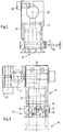
- FIG. 1 shows a suction head, in which both a suction gear 2 and a feeler foot mechanism 3 are accommodated, which generate the movement of a lifting suction device 11 or a feeler foot 7.
- the gears are only indicated here and are not the subject of the present invention.
- a cam piece 4 is mounted, on which the cam roller of a linkage 5 runs.
- the suction cup 11 is fastened to the articulation 5 and can be moved about a pivot axis 6.
- the suction lifter 11 is in the retracted position, conveying a single sheet 10 in conveyor rollers 8, which are arranged above a feed table, not shown.
- the height of a sheet stack 9 is scanned by means of the feeler foot 7 and its tracking is controlled during the continuous processing.
- a suction surface 12 is arranged on the lifting suction device 11 and, as a result of the up and down movement of the lifting suction device 11, assumes either a raised position 13 with a single sheet 10 or an extended position 14 without a single sheet 10.
- means for signal generation 17 are received on the lifting suction device 11.
- This means of Signal generation 17 can extend as a closed ring around the axis of symmetry of the suction lifter 11, so that a rotation of the lifting suction device 11 has no consequences for the signal generation.
- the signal-generating surfaces of the means for signal generation 17 can each be arranged offset by 90 ° or 120 °, or other angular divisions on the circumferential surface of the suction lifter 11.
- the means for signal generation furthermore comprise a sensor 16, which is arranged in a stationary position with respect to the lifting suction device 11 and protrudes from the lifting suction device 11.
- 15 denotes the movement path which describes the suction surface 12 with the single sheet 10 sucked in.
- the horizontal component of the movement path 15 essentially follows the course specified by the curve piece 4.
- the lifting suction device 11 executes a vertically directed movement which is used for signal generation.
- the vertical movement, the light-off movement is generated by applying a vacuum.
- the lifting suction device 11 is alternately moved back and forth between the retracted position 13 and the extended position 14 after the sheet has been picked up.
- the time required for this depends on the machine speed set in each case.
- the signal-generating surface 17 moves into the area of the sensor 16
- a signal or a pulse is generated because the lifting suction device 11 together with the gripped single sheet 10 has moved into the retracted position 13 relative to the sensor 16.
- the suction cup 11 swings back into the stacking area and tries to separate a next sheet.
- the suction surface 12 of the lifting suction device 11 can accordingly not be closed by a suctioned bow, whereby the lifting suction device 11 remains in its extended position 14. Thus, no signal can be generated between the means for signal generation 16, 17.
- the signal generation therefore only depends on the position of the sucker and is therefore independent of the nature of the substrate to be processed.
- the early detection of the last sheet allows simple means to solve the problem presented in the introduction, since it is now possible in time to adapt, for example, the vacuum in a suction belt table of a sheet feeder to the requirements of processing the last sheet. If its deformation or misalignment triggers a machine stop, for example, not only the last sheet, but all sheets currently in the rotary printing press are defective and can be attributed to the waste. If, on the other hand, timely adjustment of machine parameters such as the negative pressure in the feed table to the processing requirements of the last sheet is taken care of, consistent quality can be produced down to the last sheet.
- FIG. 2 shows a lifting suction device 11 which, in an inclined position 22, can be inclined on both sides by a few angular degrees.
- the inclined position of the suction lifter 11 is indicated by the dashed representation of the means for signal generation 17 relative to the sensor 16. Since a reliable signal generation can be carried out even with a slightly inclined lifting suction device 11, an inclination of the lifting suction device 11, which is required, for example, when processing critical printing materials, influences the timely recognition of the last sheet is not.
- a retaining plate 21 is fastened to the suction device 11 with screws 20, on which the suction device 11 strikes in the maximally extended position.
- FIG. 3 shows a lifting suction device picked up on a swivel axis in the retracted and extended position.
- the lifting suction device 11, to which the holding plate 21 is fastened by screws 20, can also be moved in relation to the pivot axis 6 after loosening a clamping screw 23 and then fixing it. With these adjustments, the signal-generating areas of the means for signal generation 17 assume the positions designated 18 and 19. Since even these are still opposite the sensor 16, an adjustment of the lifting suction device 11 relative to the pivot axis 6 is also possible. Individual measures to increase the supply security at the suction head 1 are therefore possible at any time and do not reduce the functional reliability of the means for signal generation 16, 17.
- a magnet or a ring-shaped magnet would be conceivable as means for signal generation 17, inductively operating sensors as well as sensors which comprise a photodiode or the like. Since a signal is generated in a contactless manner, the problem of contamination by paper dust can be eliminated by the sensors or sensor principles listed above.
Landscapes
- Engineering & Computer Science (AREA)
- Mechanical Engineering (AREA)
- Sheets, Magazines, And Separation Thereof (AREA)
- Controlling Sheets Or Webs (AREA)
Applications Claiming Priority (2)
| Application Number | Priority Date | Filing Date | Title |
|---|---|---|---|
| DE4416287 | 1994-05-07 | ||
| DE19944416287 DE4416287A1 (de) | 1994-05-07 | 1994-05-07 | Vorrichtung zur Signalerzeugung an einem Saugkopf |
Publications (1)
| Publication Number | Publication Date |
|---|---|
| EP0680905A1 true EP0680905A1 (fr) | 1995-11-08 |
Family
ID=6517650
Family Applications (1)
| Application Number | Title | Priority Date | Filing Date |
|---|---|---|---|
| EP95105720A Withdrawn EP0680905A1 (fr) | 1994-05-07 | 1995-04-18 | Dispositif pour générer des signaux à une tête d'aspiration |
Country Status (3)
| Country | Link |
|---|---|
| EP (1) | EP0680905A1 (fr) |
| JP (1) | JPH07300255A (fr) |
| DE (1) | DE4416287A1 (fr) |
Families Citing this family (5)
| Publication number | Priority date | Publication date | Assignee | Title |
|---|---|---|---|---|
| DE10356107B4 (de) * | 2003-11-27 | 2021-05-27 | Mabeg Systems Gmbh | Bogenanleger mit Vorderkantentrennung und berührungsloser Stapelabtastung |
| DE102007003001A1 (de) * | 2007-01-20 | 2008-07-24 | Man Roland Druckmaschinen Ag | Bogendruckmaschine |
| DE102007005403A1 (de) * | 2007-02-03 | 2008-08-07 | Man Roland Druckmaschinen Ag | Trennsaugereinrichtung für eine Bogendruckmaschine |
| DE102015202454A1 (de) | 2014-02-11 | 2015-08-13 | Koenig & Bauer Aktiengesellschaft | Bogentrenner mit mindestens einer Bogenerfassungseinheit und Verfahren an einer bogenverarbeitenden Maschine |
| DE102023104999A1 (de) | 2023-03-01 | 2024-09-05 | Koenig & Bauer Ag | Anleger einer bogenverarbeitenden Maschine und Verfahren zum Betreiben eines Anlegers einer bogenverarbeitenden Maschine |
Citations (1)
| Publication number | Priority date | Publication date | Assignee | Title |
|---|---|---|---|---|
| EP0453810A2 (fr) * | 1990-04-21 | 1991-10-30 | Heidelberger Druckmaschinen Aktiengesellschaft | Dispositif pour arrêter la buse de succion de séparateurs aspirants à la tête de succion d'un margeur de feuilles |
Family Cites Families (9)
| Publication number | Priority date | Publication date | Assignee | Title |
|---|---|---|---|---|
| DE2318443A1 (de) * | 1972-05-05 | 1973-11-22 | Polygraph Leipzig | Verfahren und einrichtungen zur vereinzelung und kontrolle von bogen |
| US3966197A (en) * | 1973-11-19 | 1976-06-29 | Veb Polygraph Leipzig Kombinat Fur Polygraphische Maschinen Und Ausrustungen | Method and apparatus for controlled feeding of sheets to printing machines or the like |
| DE2606848A1 (de) * | 1976-02-20 | 1977-09-01 | Jochen H Dipl Ing Gelbke | Einzelbogenanleger |
| DE2626605A1 (de) * | 1976-06-14 | 1977-12-15 | Canon Kk | Schalter fuer steuerungszwecke, vorzugsweise in einem elektrofotografischen kopiergeraet |
| DD149053A1 (de) * | 1980-02-06 | 1981-06-24 | Wolfgang Beyer | Kapazitive kontroll-und auswerteeinrichtung an buchbinderei-und druckmaschinen |
| DE3533247A1 (de) * | 1985-01-08 | 1986-07-10 | VEB Kombinat Polygraph "Werner Lamberz" Leipzig, DDR 7050 Leipzig | Magnetoelektrischer initiator an polygraphischen maschinen |
| DE3743805C1 (de) * | 1987-12-23 | 1989-06-01 | Heidelberger Druckmasch Ag | Trennsaugereinrichtung fuer einen Anleger einer Druckmaschine |
| DE4009175C2 (de) * | 1990-03-22 | 1998-05-20 | Georg Binnen | Hubdüsen- und Tasterlagerung für Bogenanleger |
| JP2802807B2 (ja) * | 1990-03-26 | 1998-09-24 | キヤノン株式会社 | フィルム残量検知機構 |
-
1994
- 1994-05-07 DE DE19944416287 patent/DE4416287A1/de not_active Withdrawn
-
1995
- 1995-04-18 EP EP95105720A patent/EP0680905A1/fr not_active Withdrawn
- 1995-04-28 JP JP10557795A patent/JPH07300255A/ja active Pending
Patent Citations (1)
| Publication number | Priority date | Publication date | Assignee | Title |
|---|---|---|---|---|
| EP0453810A2 (fr) * | 1990-04-21 | 1991-10-30 | Heidelberger Druckmaschinen Aktiengesellschaft | Dispositif pour arrêter la buse de succion de séparateurs aspirants à la tête de succion d'un margeur de feuilles |
Also Published As
| Publication number | Publication date |
|---|---|
| DE4416287A1 (de) | 1995-11-09 |
| JPH07300255A (ja) | 1995-11-14 |
Similar Documents
| Publication | Publication Date | Title |
|---|---|---|
| EP0284806B1 (fr) | Tête aspirante avec ventouses de levage | |
| EP0555535B1 (fr) | Procédé et dispositif pour positionner latéralement des feuilles | |
| WO2022058058A1 (fr) | Dispositif d'alimentation d'une machine de traitement de feuilles et procédé de détection et/ou de correction de feuilles divergentes en position et/ou en dimensions dans un dispositif d'alimentation d'une machine de traitement de feuilles | |
| DE102009027389B4 (de) | Anordnung zur seitlichen Ausrichtung von Bogen | |
| EP0972638A1 (fr) | Dispositif pour alimenter des feuilles vers une machine traitant ces feuilles | |
| DE3907037C2 (de) | Vorrichtung zur Bogenlängenabfrage in einer Bogen bearbeitenden Maschine | |
| DE4416287A1 (de) | Vorrichtung zur Signalerzeugung an einem Saugkopf | |
| EP0365848B1 (fr) | Dispositif ralentisseur de sortie pour une machine pour imprimer des feuilles | |
| DE3906960A1 (de) | Vorrichtung zur bogenlaengenabfrage in einer bogen bearbeitenden maschine, insbesondere einer bogen-rotationsdruckmaschine | |
| AT412338B (de) | Pneumatische trennvorrichtung | |
| DE19605420C1 (de) | Bogenleiteinrichtung | |
| EP3463888B1 (fr) | Repérage de bord avant dans une unité d'alimentation | |
| EP1593625B1 (fr) | Margeur du bord avant | |
| DE102014210110A1 (de) | Anleger für eine bogenverarbeitende Druckmaschine und Verfahren zum Betreiben eines derartigen Anlegers | |
| EP1593626A1 (fr) | Margeur du bord avant | |
| DE4234184A1 (de) | Anleger einer papierbogenverarbeitenden Maschine | |
| DE102004005575A1 (de) | Verfahren und Vorrichtung zum Steuern der Bogenzufuhr zu einer drucktechnischen Maschine | |
| DE10345488B3 (de) | Verfahren und Vorrichtung zur Detektion von Überschießbogen | |
| EP4086209B1 (fr) | Dispositif et procédé de séparation de marchandises plates et d'alimentation d'une unité d'usinage | |
| DE3912458C2 (de) | Einrichtung zum kontinuierlichen Vorausrichten der Bogenvorderkante in Bogenanlegern | |
| EP0771747B1 (fr) | Méthode pour séparer de matériaux en feuille pour une machine de traitement | |
| DE102015209905A1 (de) | Kontrolleinrichtung zum Überwachen eines Grenzwerts einer Schichtdicke und/oder einer Anzahl von mehreren zumindest teilweise aufeinander liegenden Materialabschnitten in einem Fühlspalt | |
| EP3463886B1 (fr) | Unité d'alimentation pour une machine d'impression rotative à feuilles | |
| DE4214232C1 (de) | Bogenanleger mit im bereich der stapelhinterkante angeordneten trennsaugern | |
| EP0939739B1 (fr) | Dispositif d'alimentation en feuilles du tambour transporteur de feuilles d'une machine a imprimer |
Legal Events
| Date | Code | Title | Description |
|---|---|---|---|
| PUAI | Public reference made under article 153(3) epc to a published international application that has entered the european phase |
Free format text: ORIGINAL CODE: 0009012 |
|
| 17P | Request for examination filed |
Effective date: 19950418 |
|
| AK | Designated contracting states |
Kind code of ref document: A1 Designated state(s): CH DE FR GB IT LI NL |
|
| GBC | Gb: translation of claims filed (gb section 78(7)/1977) | ||
| 17Q | First examination report despatched |
Effective date: 19960620 |
|
| GRAG | Despatch of communication of intention to grant |
Free format text: ORIGINAL CODE: EPIDOS AGRA |
|
| STAA | Information on the status of an ep patent application or granted ep patent |
Free format text: STATUS: THE APPLICATION HAS BEEN WITHDRAWN |
|
| 18W | Application withdrawn |
Withdrawal date: 19970610 |