EP0680923B1 - Arbeitsmaschine - Google Patents
Arbeitsmaschine Download PDFInfo
- Publication number
- EP0680923B1 EP0680923B1 EP95302681A EP95302681A EP0680923B1 EP 0680923 B1 EP0680923 B1 EP 0680923B1 EP 95302681 A EP95302681 A EP 95302681A EP 95302681 A EP95302681 A EP 95302681A EP 0680923 B1 EP0680923 B1 EP 0680923B1
- Authority
- EP
- European Patent Office
- Prior art keywords
- boom
- carriage
- tool
- extension
- machine
- Prior art date
- Legal status (The legal status is an assumption and is not a legal conclusion. Google has not performed a legal analysis and makes no representation as to the accuracy of the status listed.)
- Expired - Lifetime
Links
- 238000005452 bending Methods 0.000 description 1
- 238000010276 construction Methods 0.000 description 1
- 238000005096 rolling process Methods 0.000 description 1
Images


Classifications
-
- E—FIXED CONSTRUCTIONS
- E02—HYDRAULIC ENGINEERING; FOUNDATIONS; SOIL SHIFTING
- E02F—DREDGING; SOIL-SHIFTING
- E02F3/00—Dredgers; Soil-shifting machines
- E02F3/04—Dredgers; Soil-shifting machines mechanically-driven
- E02F3/28—Dredgers; Soil-shifting machines mechanically-driven with digging tools mounted on a dipper- or bucket-arm, i.e. there is either one arm or a pair of arms, e.g. dippers, buckets
- E02F3/283—Dredgers; Soil-shifting machines mechanically-driven with digging tools mounted on a dipper- or bucket-arm, i.e. there is either one arm or a pair of arms, e.g. dippers, buckets with a single arm pivoted directly on the chassis
- E02F3/286—Dredgers; Soil-shifting machines mechanically-driven with digging tools mounted on a dipper- or bucket-arm, i.e. there is either one arm or a pair of arms, e.g. dippers, buckets with a single arm pivoted directly on the chassis telescopic or slidable
-
- B—PERFORMING OPERATIONS; TRANSPORTING
- B66—HOISTING; LIFTING; HAULING
- B66F—HOISTING, LIFTING, HAULING OR PUSHING, NOT OTHERWISE PROVIDED FOR, e.g. DEVICES WHICH APPLY A LIFTING OR PUSHING FORCE DIRECTLY TO THE SURFACE OF A LOAD
- B66F9/00—Devices for lifting or lowering bulky or heavy goods for loading or unloading purposes
- B66F9/06—Devices for lifting or lowering bulky or heavy goods for loading or unloading purposes movable, with their loads, on wheels or the like, e.g. fork-lift trucks
- B66F9/065—Devices for lifting or lowering bulky or heavy goods for loading or unloading purposes movable, with their loads, on wheels or the like, e.g. fork-lift trucks non-masted
- B66F9/0655—Devices for lifting or lowering bulky or heavy goods for loading or unloading purposes movable, with their loads, on wheels or the like, e.g. fork-lift trucks non-masted with a telescopic boom
-
- Y—GENERAL TAGGING OF NEW TECHNOLOGICAL DEVELOPMENTS; GENERAL TAGGING OF CROSS-SECTIONAL TECHNOLOGIES SPANNING OVER SEVERAL SECTIONS OF THE IPC; TECHNICAL SUBJECTS COVERED BY FORMER USPC CROSS-REFERENCE ART COLLECTIONS [XRACs] AND DIGESTS
- Y10—TECHNICAL SUBJECTS COVERED BY FORMER USPC
- Y10S—TECHNICAL SUBJECTS COVERED BY FORMER USPC CROSS-REFERENCE ART COLLECTIONS [XRACs] AND DIGESTS
- Y10S414/00—Material or article handling
- Y10S414/13—Handlers utilizing parallel links
Definitions
- the present invention relates to a work machine comprising a boom which is pivotally connected at one end to the machine body and is provided at the other end with a tool carriage attached to the boom at a pivot which is fixed with respect to the boom, the carriage being associated with a mechanism for keeping it at a constant attitude when the boom is raised and lowered, and an elongate boom extension comprising a parallelogram linkage having a pair of parallel links each pivotally connected at one end to a tool, a first one of the links being connected at its other end at or adjacent to the pivot of the tool carriage.
- a work machine is referred to as of the kind described and is known for example in document EP-A-0 228 208.
- a load which is to be moved by such a work machine is to be picked up from or deposited at a location, for example, deep within a container or high above the machine, it is possible that the boom may not be long enough to reach the location.
- a machine of the kind described is characterised in that the second one of the links is pivotally connected to the tool carriage such that the tool follows the attitude of the tool carriage when the boom is raised and lowered, and in that an additional link is pivotally attached at one end to the tool, and at the other end to the boom at a location spaced from the carriage.
- the first link When the boom is raised and lowered, the first link does not follow the rotation of the carriage but rotates relatively to it. Thus, the other ends of the first and second links are moved relatively to one another thereby cranking the parallelogram linkage in such a way as to maintain the tool at a constant attitude.
- This arrangement ensures that the extension always remains substantially parallel to the boom, so that the bending moments on the boom are kept to a minimum.
- an additional link may be pivotally attached at one end to the tool, and at the other end to the boom at a location spaced from the carriage.
- the boom is preferably telescopic.
- the machine is preferably a vehicle.
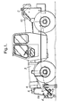
- FIG. 1 A vehicle to which the boom extension can be attached is shown in Fig. 1.
- the vehicle has a boom 1 which is pivotally mounted at a pivot 2 extending transversely to the longitudinal axis of the vehicle.
- the boom 1 comprises outer 3, intermediate 4 and inner 5 portions telescopically coupled together.
- the inner portion 5 has a depending bracket portion 5A.
- the inner portion 5 is provided at the extremity of the bracket portion 5A with a tool carriage 6 which is pivotally mounted to the bracket 5A at pivot 7.
- the angular position of the carriage 6 is adjustable via a linkage 8 which is pivotally connected at one end to the carriage 6 and at the other end to a hydraulic cylinder 9 which is pivotally mounted to the bracket portion 5A of the boom.
- This hydraulic cylinder 9 is hydraulically coupled by a rolling hose coiled within the boom 1 to a compensating hydraulic cylinder 10 which is positioned in such a way that the oil displaced from the compensating cylinder 10 when the boom is raised and lowered changes the length of the cylinder 9 and hence automatically adjusts the angle of the carriage 6.
- a conventional tool which is attached to the carriage can be kept at a constant attitude when the boom 1 is raised and lowered.
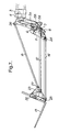
- the boom extension B is provided at one end with an attachment 11 which is attached to the carriage 6 by a quick hitch device such that it does not rotate with respect to the carriage 6.
- a first link 12 is attached to the pivot 7 so that it can rotate relatively to the boom 1 and carriage 6.
- the opposite end of each first link 12 is pivotally connected to the conventional tool such as a fork 13.
- a second link 14 is pivotally connected to the attachment 11 at one end and at the opposite end to the fork 13.
- the first 12 and second 14 links are the same length so as to provide a parallelogram linkage.
- the parallelogram linkage is stabilised by a third link 15 which is pivotally connected at one end to the boom at a location remote from the carriage 6, and at the other end to the fork 13 at a position adjacent to the pivotal connection for the opposite end of the first link 12.
- the quick hitch device comprises a pair of hooks 16 which hook over respective pins 17 carried by the carriage 6. With these hooks engaged, pins 18 are inserted through aligned apertures in the attachment 11 and carriage 6 to secure the attachment to the carriage.
- the linkage 8 interconnecting the hydraulic cylinder 9 with the carriage 6 comprises a bell crank 8A, which is pivoted at 19 to the bracket 5A and is pivoted at one end 20 to the ram and at its other end 21 to one end of a link 8B, the other end of which is pivoted at 22 to the carriage 6.
- the bell crank 8A is caused to rotate in a clockwise direction as seen in Figs. 5 and 7 thus closing the angle between the bell crank 8A and the link 8B and simultaneously rotating the carriage 6 and, when fitted, attachment 11, in a clockwise direction as seen in these figures.
- the fork or other tool 13 then follows this rotation by virtue of the parallelogram linkage 12,14 and Fig.
- FIG. 7 shows the fully extended position of the ram 9 in which the forks 13 are shown fully rolled back extending at 20° above the horizontal, with the boom extending horizontally. Similarly retraction of the ram 9 will rotate the parts in the anti-clockwise direction until the forks 13 are extending perpendicularly to the boom as shown in the right hand part of Fig. 4.
- Figs. 5 to 7 show the end pivots for the links 12,14 and 15 at 7 and 23,24 and 25, and 26 and 27, respectively.
- the pivots 23 and 25 are to webs 28, and the pivot 27 to a web 29, the webs 28 and 29 projecting from a back frame 30 of the fork tool.
- the boom extension reacts as follows.
- the carriage 6 and attachment 11 are maintained at the same attitude, while the first link 12 is rotated with respect to the carriage 6 and attachment 11. This cranks the parallelogram linkage round in such a way as to maintain the fork 13 at a constant attitude as shown in Figs. 2 to 4.
- envelope A The range of movement attainable by the tool is shown by envelope A in Fig. 4.
- the radially innermost corners of this envelope are those positions in which the boom 1 is fully telescopically retracted, and the radially outermost corners of the envelope are those in which the boom is telescopically fully extended.
Landscapes
- Engineering & Computer Science (AREA)
- Structural Engineering (AREA)
- Mechanical Engineering (AREA)
- Civil Engineering (AREA)
- Transportation (AREA)
- Mining & Mineral Resources (AREA)
- General Engineering & Computer Science (AREA)
- Life Sciences & Earth Sciences (AREA)
- Geology (AREA)
- Forklifts And Lifting Vehicles (AREA)
Claims (2)
- Eine Arbeitsmaschine, die einen Ausleger (1) aufweist, der an einem Ende schwenkbar mit dem Maschinenkörper verbunden ist, und der an dem anderen Ende mit einem Werkzeugträger (6) versehen ist, der an dem Ausleger an einem Schwenkstift (7) befestigt ist, der im Hinblick auf den Ausleger fixiert ist, wobei der Träger mit einem Mechanismus (8) assoziiert ist, um ihn in einer konstanten Stellung zu halten, wenn der Ausleger angehoben und abgesenkt wird, und eine langgestreckte Auslegerverlängerung (B), die eine Parallelogramm-Kopplung aufweist, die ein Paar paralleler Verbindungen (12, 14) hat, von denen jede an einem Ende schwenkbar mit einem Werkzeug (13) verbunden ist, wobei eine erste (12) der Verbindungen an ihrem anderen Ende mit oder benachbart zu dem Schwenkstift des Werkzeugträgers verbunden ist; dadurch gekennzeichnet, daßdie zweite (14) der Verbindungen schwenkbar mit dem Werkzeugträger verbunden ist, so daß das Werkzeug der Stellung des Werkzeugträgers folgt, wenn der Ausleger angehoben und abgesenkt wird; und daßeine zusätzliche Verbindung (15) an einem Ende an dem Werkzeug (13) und an einem anderen Ende an dem Ausleger (1) an einer von dem Träger (6) beabstandeten Stelle schwenkbar befestigt ist.
- Eine Arbeitsmaschine nach Anspruch 1, wobei die Maschine ein Fahrzeug ist.
Applications Claiming Priority (2)
| Application Number | Priority Date | Filing Date | Title |
|---|---|---|---|
| GB9408781A GB9408781D0 (en) | 1994-05-04 | 1994-05-04 | Work vehicle |
| GB9408781 | 1994-05-04 |
Publications (2)
| Publication Number | Publication Date |
|---|---|
| EP0680923A1 EP0680923A1 (de) | 1995-11-08 |
| EP0680923B1 true EP0680923B1 (de) | 2001-07-04 |
Family
ID=10754500
Family Applications (1)
| Application Number | Title | Priority Date | Filing Date |
|---|---|---|---|
| EP95302681A Expired - Lifetime EP0680923B1 (de) | 1994-05-04 | 1995-04-21 | Arbeitsmaschine |
Country Status (4)
| Country | Link |
|---|---|
| US (1) | US5577878A (de) |
| EP (1) | EP0680923B1 (de) |
| DE (1) | DE69521557T2 (de) |
| GB (1) | GB9408781D0 (de) |
Families Citing this family (8)
| Publication number | Priority date | Publication date | Assignee | Title |
|---|---|---|---|---|
| DE69800866T2 (de) * | 1998-04-17 | 2001-11-15 | Liftcon Technologies Ltd., Shannon | Transportabler Gabelhubwagen mit teleskopischem Hebearm |
| IT1304978B1 (it) * | 1998-09-10 | 2001-04-05 | Merlo Ind Metalmecc | Veicolo utilizzabile come sollevatore e trattore agricolo. |
| FR2788759B1 (fr) | 1999-01-27 | 2001-03-23 | Sambron | Dispositif de controle de deplacement d'une structure portante d'engin roulant et engin roulant incorporant ledit dispositif |
| FR2797625B1 (fr) | 1999-08-18 | 2001-11-02 | Sambron | Dispositif de correction de devers pour plate-forme a deux essieux |
| DE19938578A1 (de) * | 1999-08-18 | 2001-02-22 | Delmag Maschinenfabrik | Fahrbares Arbeitsgerät |
| IT1396035B1 (it) * | 2009-10-19 | 2012-11-09 | Boat Eagle S R L | Veicolo sollevatore, in particolare per il rimessaggio di imbarcazioni |
| GB2526356B (en) * | 2014-05-23 | 2018-08-01 | Abt Products Ltd | A forklift arrangement with parallel linkage |
| US10662046B1 (en) * | 2018-12-21 | 2020-05-26 | Altec Industries, Inc. | Boom-mountable material handler |
Family Cites Families (14)
| Publication number | Priority date | Publication date | Assignee | Title |
|---|---|---|---|---|
| US3070244A (en) * | 1958-10-13 | 1962-12-25 | Le Grand H Lull | Loader |
| FR1434973A (fr) * | 1964-09-24 | 1966-04-15 | Poclain Sa | Dispositif de commande à parallélogramme déformable, de l'outil de travail d'un engin tel qu'un niveleur |
| US3647099A (en) * | 1969-12-11 | 1972-03-07 | Pettibone Corp | Interposable mast |
| US3792786A (en) * | 1972-02-17 | 1974-02-19 | V Goikhburg | Single-bucket excavator |
| GB1472069A (en) * | 1974-03-12 | 1977-04-27 | Hy Mac Ltd | Hydraulically operated shovels |
| FR2389722B1 (de) * | 1977-05-04 | 1983-03-04 | Poclain Sa | |
| US4744718A (en) * | 1984-03-06 | 1988-05-17 | Gleason Cranes (Vic.) Pty. Ltd. | Aircraft service vehicle |
| DD229387A1 (de) * | 1984-12-07 | 1985-11-06 | Vta Leipzig Paul Froehlich Veb | Hubvorrichtung, insbesondere fuer gabelstapler |
| US4822237A (en) * | 1985-11-21 | 1989-04-18 | The Gradall Company | Extended reach materials handling apparatus |
| US4674944A (en) * | 1985-12-27 | 1987-06-23 | Kidde, Inc. | Forklift variable reach mechanism |
| US4826474A (en) * | 1987-12-14 | 1989-05-02 | Butterworth Jetting Systems, Inc. | Forklift apparatus for unloading articles from an elevated surface |
| US5226776A (en) * | 1988-05-17 | 1993-07-13 | Godtfred Vestergaard | Foldable link rod for carrying an operative platform |
| IT1234635B (it) * | 1989-07-07 | 1992-05-26 | Manitou Costr Ind Srl | Gruppo cestello porta persone per elevatore semovente |
| US4964778A (en) * | 1989-07-27 | 1990-10-23 | Kidde Industries, Inc. | Forklift truck having a telescopic auxiliary boom articulated to a telescopic main boom |
-
1994
- 1994-05-04 GB GB9408781A patent/GB9408781D0/en active Pending
-
1995
- 1995-04-21 EP EP95302681A patent/EP0680923B1/de not_active Expired - Lifetime
- 1995-04-21 DE DE69521557T patent/DE69521557T2/de not_active Expired - Fee Related
- 1995-05-01 US US08/432,275 patent/US5577878A/en not_active Expired - Lifetime
Also Published As
| Publication number | Publication date |
|---|---|
| EP0680923A1 (de) | 1995-11-08 |
| DE69521557T2 (de) | 2001-11-15 |
| DE69521557D1 (de) | 2001-08-09 |
| US5577878A (en) | 1996-11-26 |
| GB9408781D0 (en) | 1994-06-22 |
Similar Documents
| Publication | Publication Date | Title |
|---|---|---|
| US5895197A (en) | Cable reel handler | |
| JPH07500153A (ja) | 工具動作装置 | |
| EP0680923B1 (de) | Arbeitsmaschine | |
| US4529215A (en) | Hydraulic cylinder safety lock | |
| GB2202122A (en) | Vegetation cutting apparatus | |
| EP1531141B1 (de) | Transportabler Gabelhubwagen | |
| US4775287A (en) | Adjustable boom | |
| JP2796950B2 (ja) | カウンタウエイトの脱着装置 | |
| US6547217B1 (en) | Variable reach lift arm | |
| CA2313848A1 (en) | Vehicle implement interface | |
| US6910544B2 (en) | Work machine arrangement | |
| US20020079109A1 (en) | Earth-moving machine | |
| US7111419B1 (en) | Thumb for a backhoe | |
| US5028085A (en) | Bale handling implement | |
| US7357263B2 (en) | Articulating jib | |
| CN111137795A (zh) | 负载装卸工具的保持装置及包括此保持装置的液压起重机 | |
| US8834090B1 (en) | Grappling fork attachment system | |
| RU2158207C1 (ru) | Манипулятор | |
| EP2197779B1 (de) | Gelenkiger mechanischer arm | |
| JP4248667B2 (ja) | 高所作業車の作業台の姿勢維持装置 | |
| JPH0120398Y2 (de) | ||
| JP2002120992A (ja) | 油圧ジャッキ | |
| JPH0653582U (ja) | ブームを有する作業機のブーム起伏角度検出装置 | |
| JP2024061474A (ja) | アウトリガ装置、アウトリガ装置を用いた産業用機械の積み込み方法及び積み下ろし方法 | |
| JPS6123289Y2 (de) |
Legal Events
| Date | Code | Title | Description |
|---|---|---|---|
| PUAI | Public reference made under article 153(3) epc to a published international application that has entered the european phase |
Free format text: ORIGINAL CODE: 0009012 |
|
| AK | Designated contracting states |
Kind code of ref document: A1 Designated state(s): DE GB IT |
|
| 17P | Request for examination filed |
Effective date: 19960419 |
|
| 17Q | First examination report despatched |
Effective date: 19990709 |
|
| GRAG | Despatch of communication of intention to grant |
Free format text: ORIGINAL CODE: EPIDOS AGRA |
|
| GRAG | Despatch of communication of intention to grant |
Free format text: ORIGINAL CODE: EPIDOS AGRA |
|
| GRAH | Despatch of communication of intention to grant a patent |
Free format text: ORIGINAL CODE: EPIDOS IGRA |
|
| GRAH | Despatch of communication of intention to grant a patent |
Free format text: ORIGINAL CODE: EPIDOS IGRA |
|
| GRAA | (expected) grant |
Free format text: ORIGINAL CODE: 0009210 |
|
| AK | Designated contracting states |
Kind code of ref document: B1 Designated state(s): DE GB IT |
|
| REF | Corresponds to: |
Ref document number: 69521557 Country of ref document: DE Date of ref document: 20010809 |
|
| ITF | It: translation for a ep patent filed | ||
| REG | Reference to a national code |
Ref country code: GB Ref legal event code: IF02 |
|
| PLBE | No opposition filed within time limit |
Free format text: ORIGINAL CODE: 0009261 |
|
| STAA | Information on the status of an ep patent application or granted ep patent |
Free format text: STATUS: NO OPPOSITION FILED WITHIN TIME LIMIT |
|
| 26N | No opposition filed | ||
| PGFP | Annual fee paid to national office [announced via postgrant information from national office to epo] |
Ref country code: GB Payment date: 20040312 Year of fee payment: 10 |
|
| PGFP | Annual fee paid to national office [announced via postgrant information from national office to epo] |
Ref country code: DE Payment date: 20040430 Year of fee payment: 10 |
|
| PG25 | Lapsed in a contracting state [announced via postgrant information from national office to epo] |
Ref country code: IT Free format text: LAPSE BECAUSE OF NON-PAYMENT OF DUE FEES;WARNING: LAPSES OF ITALIAN PATENTS WITH EFFECTIVE DATE BEFORE 2007 MAY HAVE OCCURRED AT ANY TIME BEFORE 2007. THE CORRECT EFFECTIVE DATE MAY BE DIFFERENT FROM THE ONE RECORDED. Effective date: 20050421 Ref country code: GB Free format text: LAPSE BECAUSE OF NON-PAYMENT OF DUE FEES Effective date: 20050421 |
|
| PG25 | Lapsed in a contracting state [announced via postgrant information from national office to epo] |
Ref country code: DE Free format text: LAPSE BECAUSE OF NON-PAYMENT OF DUE FEES Effective date: 20051101 |
|
| GBPC | Gb: european patent ceased through non-payment of renewal fee |
Effective date: 20050421 |