EP0681024B1 - Verbesserter Träger für biologische Züchtung und Verfahren zur Herstellung - Google Patents
Verbesserter Träger für biologische Züchtung und Verfahren zur Herstellung Download PDFInfo
- Publication number
- EP0681024B1 EP0681024B1 EP95302871A EP95302871A EP0681024B1 EP 0681024 B1 EP0681024 B1 EP 0681024B1 EP 95302871 A EP95302871 A EP 95302871A EP 95302871 A EP95302871 A EP 95302871A EP 0681024 B1 EP0681024 B1 EP 0681024B1
- Authority
- EP
- European Patent Office
- Prior art keywords
- slide
- adhesive
- compartment
- lower margin
- culture
- Prior art date
- Legal status (The legal status is an assumption and is not a legal conclusion. Google has not performed a legal analysis and makes no representation as to the accuracy of the status listed.)
- Expired - Lifetime
Links
Images

Classifications
-
- B—PERFORMING OPERATIONS; TRANSPORTING
- B01—PHYSICAL OR CHEMICAL PROCESSES OR APPARATUS IN GENERAL
- B01L—CHEMICAL OR PHYSICAL LABORATORY APPARATUS FOR GENERAL USE
- B01L3/00—Containers or dishes for laboratory use, e.g. laboratory glassware; Droppers
- B01L3/50—Containers for the purpose of retaining a material to be analysed, e.g. test tubes
- B01L3/508—Rigid containers without fluid transport within
- B01L3/5085—Rigid containers without fluid transport within for multiple samples, e.g. microtitration plates
-
- B—PERFORMING OPERATIONS; TRANSPORTING
- B29—WORKING OF PLASTICS; WORKING OF SUBSTANCES IN A PLASTIC STATE IN GENERAL
- B29C—SHAPING OR JOINING OF PLASTICS; SHAPING OF MATERIAL IN A PLASTIC STATE, NOT OTHERWISE PROVIDED FOR; AFTER-TREATMENT OF THE SHAPED PRODUCTS, e.g. REPAIRING
- B29C65/00—Joining or sealing of preformed parts, e.g. welding of plastics materials; Apparatus therefor
- B29C65/48—Joining or sealing of preformed parts, e.g. welding of plastics materials; Apparatus therefor using adhesives, i.e. using supplementary joining material; solvent bonding
- B29C65/50—Joining or sealing of preformed parts, e.g. welding of plastics materials; Apparatus therefor using adhesives, i.e. using supplementary joining material; solvent bonding using adhesive tape, e.g. thermoplastic tape; using threads or the like
- B29C65/5007—Joining or sealing of preformed parts, e.g. welding of plastics materials; Apparatus therefor using adhesives, i.e. using supplementary joining material; solvent bonding using adhesive tape, e.g. thermoplastic tape; using threads or the like characterised by the structure of said adhesive tape, threads or the like
- B29C65/5021—Joining or sealing of preformed parts, e.g. welding of plastics materials; Apparatus therefor using adhesives, i.e. using supplementary joining material; solvent bonding using adhesive tape, e.g. thermoplastic tape; using threads or the like characterised by the structure of said adhesive tape, threads or the like being multi-layered
-
- B—PERFORMING OPERATIONS; TRANSPORTING
- B29—WORKING OF PLASTICS; WORKING OF SUBSTANCES IN A PLASTIC STATE IN GENERAL
- B29C—SHAPING OR JOINING OF PLASTICS; SHAPING OF MATERIAL IN A PLASTIC STATE, NOT OTHERWISE PROVIDED FOR; AFTER-TREATMENT OF THE SHAPED PRODUCTS, e.g. REPAIRING
- B29C65/00—Joining or sealing of preformed parts, e.g. welding of plastics materials; Apparatus therefor
- B29C65/48—Joining or sealing of preformed parts, e.g. welding of plastics materials; Apparatus therefor using adhesives, i.e. using supplementary joining material; solvent bonding
- B29C65/50—Joining or sealing of preformed parts, e.g. welding of plastics materials; Apparatus therefor using adhesives, i.e. using supplementary joining material; solvent bonding using adhesive tape, e.g. thermoplastic tape; using threads or the like
- B29C65/5057—Joining or sealing of preformed parts, e.g. welding of plastics materials; Apparatus therefor using adhesives, i.e. using supplementary joining material; solvent bonding using adhesive tape, e.g. thermoplastic tape; using threads or the like positioned between the surfaces to be joined
-
- B—PERFORMING OPERATIONS; TRANSPORTING
- B29—WORKING OF PLASTICS; WORKING OF SUBSTANCES IN A PLASTIC STATE IN GENERAL
- B29C—SHAPING OR JOINING OF PLASTICS; SHAPING OF MATERIAL IN A PLASTIC STATE, NOT OTHERWISE PROVIDED FOR; AFTER-TREATMENT OF THE SHAPED PRODUCTS, e.g. REPAIRING
- B29C65/00—Joining or sealing of preformed parts, e.g. welding of plastics materials; Apparatus therefor
- B29C65/48—Joining or sealing of preformed parts, e.g. welding of plastics materials; Apparatus therefor using adhesives, i.e. using supplementary joining material; solvent bonding
- B29C65/52—Joining or sealing of preformed parts, e.g. welding of plastics materials; Apparatus therefor using adhesives, i.e. using supplementary joining material; solvent bonding characterised by the way of applying the adhesive
-
- B—PERFORMING OPERATIONS; TRANSPORTING
- B29—WORKING OF PLASTICS; WORKING OF SUBSTANCES IN A PLASTIC STATE IN GENERAL
- B29C—SHAPING OR JOINING OF PLASTICS; SHAPING OF MATERIAL IN A PLASTIC STATE, NOT OTHERWISE PROVIDED FOR; AFTER-TREATMENT OF THE SHAPED PRODUCTS, e.g. REPAIRING
- B29C65/00—Joining or sealing of preformed parts, e.g. welding of plastics materials; Apparatus therefor
- B29C65/76—Making non-permanent or releasable joints
-
- B—PERFORMING OPERATIONS; TRANSPORTING
- B29—WORKING OF PLASTICS; WORKING OF SUBSTANCES IN A PLASTIC STATE IN GENERAL
- B29C—SHAPING OR JOINING OF PLASTICS; SHAPING OF MATERIAL IN A PLASTIC STATE, NOT OTHERWISE PROVIDED FOR; AFTER-TREATMENT OF THE SHAPED PRODUCTS, e.g. REPAIRING
- B29C66/00—General aspects of processes or apparatus for joining preformed parts
- B29C66/01—General aspects dealing with the joint area or with the area to be joined
- B29C66/05—Particular design of joint configurations
- B29C66/10—Particular design of joint configurations particular design of the joint cross-sections
- B29C66/11—Joint cross-sections comprising a single joint-segment, i.e. one of the parts to be joined comprising a single joint-segment in the joint cross-section
- B29C66/112—Single lapped joints
- B29C66/1122—Single lap to lap joints, i.e. overlap joints
-
- B—PERFORMING OPERATIONS; TRANSPORTING
- B29—WORKING OF PLASTICS; WORKING OF SUBSTANCES IN A PLASTIC STATE IN GENERAL
- B29C—SHAPING OR JOINING OF PLASTICS; SHAPING OF MATERIAL IN A PLASTIC STATE, NOT OTHERWISE PROVIDED FOR; AFTER-TREATMENT OF THE SHAPED PRODUCTS, e.g. REPAIRING
- B29C66/00—General aspects of processes or apparatus for joining preformed parts
- B29C66/01—General aspects dealing with the joint area or with the area to be joined
- B29C66/05—Particular design of joint configurations
- B29C66/10—Particular design of joint configurations particular design of the joint cross-sections
- B29C66/11—Joint cross-sections comprising a single joint-segment, i.e. one of the parts to be joined comprising a single joint-segment in the joint cross-section
- B29C66/114—Single butt joints
-
- B—PERFORMING OPERATIONS; TRANSPORTING
- B29—WORKING OF PLASTICS; WORKING OF SUBSTANCES IN A PLASTIC STATE IN GENERAL
- B29C—SHAPING OR JOINING OF PLASTICS; SHAPING OF MATERIAL IN A PLASTIC STATE, NOT OTHERWISE PROVIDED FOR; AFTER-TREATMENT OF THE SHAPED PRODUCTS, e.g. REPAIRING
- B29C66/00—General aspects of processes or apparatus for joining preformed parts
- B29C66/01—General aspects dealing with the joint area or with the area to be joined
- B29C66/05—Particular design of joint configurations
- B29C66/10—Particular design of joint configurations particular design of the joint cross-sections
- B29C66/13—Single flanged joints; Fin-type joints; Single hem joints; Edge joints; Interpenetrating fingered joints; Other specific particular designs of joint cross-sections not provided for in groups B29C66/11 - B29C66/12
- B29C66/131—Single flanged joints, i.e. one of the parts to be joined being rigid and flanged in the joint area
-
- B—PERFORMING OPERATIONS; TRANSPORTING
- B29—WORKING OF PLASTICS; WORKING OF SUBSTANCES IN A PLASTIC STATE IN GENERAL
- B29C—SHAPING OR JOINING OF PLASTICS; SHAPING OF MATERIAL IN A PLASTIC STATE, NOT OTHERWISE PROVIDED FOR; AFTER-TREATMENT OF THE SHAPED PRODUCTS, e.g. REPAIRING
- B29C66/00—General aspects of processes or apparatus for joining preformed parts
- B29C66/01—General aspects dealing with the joint area or with the area to be joined
- B29C66/05—Particular design of joint configurations
- B29C66/20—Particular design of joint configurations particular design of the joint lines, e.g. of the weld lines
- B29C66/24—Particular design of joint configurations particular design of the joint lines, e.g. of the weld lines said joint lines being closed or non-straight
- B29C66/242—Particular design of joint configurations particular design of the joint lines, e.g. of the weld lines said joint lines being closed or non-straight said joint lines being closed, i.e. forming closed contours
- B29C66/2424—Particular design of joint configurations particular design of the joint lines, e.g. of the weld lines said joint lines being closed or non-straight said joint lines being closed, i.e. forming closed contours being a closed polygonal chain
- B29C66/24243—Particular design of joint configurations particular design of the joint lines, e.g. of the weld lines said joint lines being closed or non-straight said joint lines being closed, i.e. forming closed contours being a closed polygonal chain forming a quadrilateral
- B29C66/24244—Particular design of joint configurations particular design of the joint lines, e.g. of the weld lines said joint lines being closed or non-straight said joint lines being closed, i.e. forming closed contours being a closed polygonal chain forming a quadrilateral forming a rectangle
-
- B—PERFORMING OPERATIONS; TRANSPORTING
- B29—WORKING OF PLASTICS; WORKING OF SUBSTANCES IN A PLASTIC STATE IN GENERAL
- B29C—SHAPING OR JOINING OF PLASTICS; SHAPING OF MATERIAL IN A PLASTIC STATE, NOT OTHERWISE PROVIDED FOR; AFTER-TREATMENT OF THE SHAPED PRODUCTS, e.g. REPAIRING
- B29C66/00—General aspects of processes or apparatus for joining preformed parts
- B29C66/50—General aspects of joining tubular articles; General aspects of joining long products, i.e. bars or profiled elements; General aspects of joining single elements to tubular articles, hollow articles or bars; General aspects of joining several hollow-preforms to form hollow or tubular articles
- B29C66/51—Joining tubular articles, profiled elements or bars; Joining single elements to tubular articles, hollow articles or bars; Joining several hollow-preforms to form hollow or tubular articles
- B29C66/53—Joining single elements to tubular articles, hollow articles or bars
- B29C66/534—Joining single elements to open ends of tubular or hollow articles or to the ends of bars
- B29C66/5346—Joining single elements to open ends of tubular or hollow articles or to the ends of bars said single elements being substantially flat
- B29C66/53461—Joining single elements to open ends of tubular or hollow articles or to the ends of bars said single elements being substantially flat joining substantially flat covers and/or substantially flat bottoms to open ends of container bodies
-
- C—CHEMISTRY; METALLURGY
- C12—BIOCHEMISTRY; BEER; SPIRITS; WINE; VINEGAR; MICROBIOLOGY; ENZYMOLOGY; MUTATION OR GENETIC ENGINEERING
- C12M—APPARATUS FOR ENZYMOLOGY OR MICROBIOLOGY; APPARATUS FOR CULTURING MICROORGANISMS FOR PRODUCING BIOMASS, FOR GROWING CELLS OR FOR OBTAINING FERMENTATION OR METABOLIC PRODUCTS, i.e. BIOREACTORS OR FERMENTERS
- C12M23/00—Constructional details, e.g. recesses, hinges
- C12M23/02—Form or structure of the vessel
- C12M23/04—Flat or tray type, drawers
-
- C—CHEMISTRY; METALLURGY
- C12—BIOCHEMISTRY; BEER; SPIRITS; WINE; VINEGAR; MICROBIOLOGY; ENZYMOLOGY; MUTATION OR GENETIC ENGINEERING
- C12M—APPARATUS FOR ENZYMOLOGY OR MICROBIOLOGY; APPARATUS FOR CULTURING MICROORGANISMS FOR PRODUCING BIOMASS, FOR GROWING CELLS OR FOR OBTAINING FERMENTATION OR METABOLIC PRODUCTS, i.e. BIOREACTORS OR FERMENTERS
- C12M23/00—Constructional details, e.g. recesses, hinges
- C12M23/20—Material Coatings
-
- C—CHEMISTRY; METALLURGY
- C12—BIOCHEMISTRY; BEER; SPIRITS; WINE; VINEGAR; MICROBIOLOGY; ENZYMOLOGY; MUTATION OR GENETIC ENGINEERING
- C12M—APPARATUS FOR ENZYMOLOGY OR MICROBIOLOGY; APPARATUS FOR CULTURING MICROORGANISMS FOR PRODUCING BIOMASS, FOR GROWING CELLS OR FOR OBTAINING FERMENTATION OR METABOLIC PRODUCTS, i.e. BIOREACTORS OR FERMENTERS
- C12M23/00—Constructional details, e.g. recesses, hinges
- C12M23/34—Internal compartments or partitions
-
- C—CHEMISTRY; METALLURGY
- C12—BIOCHEMISTRY; BEER; SPIRITS; WINE; VINEGAR; MICROBIOLOGY; ENZYMOLOGY; MUTATION OR GENETIC ENGINEERING
- C12M—APPARATUS FOR ENZYMOLOGY OR MICROBIOLOGY; APPARATUS FOR CULTURING MICROORGANISMS FOR PRODUCING BIOMASS, FOR GROWING CELLS OR FOR OBTAINING FERMENTATION OR METABOLIC PRODUCTS, i.e. BIOREACTORS OR FERMENTERS
- C12M23/00—Constructional details, e.g. recesses, hinges
- C12M23/38—Caps; Covers; Plugs; Pouring means
-
- C—CHEMISTRY; METALLURGY
- C12—BIOCHEMISTRY; BEER; SPIRITS; WINE; VINEGAR; MICROBIOLOGY; ENZYMOLOGY; MUTATION OR GENETIC ENGINEERING
- C12M—APPARATUS FOR ENZYMOLOGY OR MICROBIOLOGY; APPARATUS FOR CULTURING MICROORGANISMS FOR PRODUCING BIOMASS, FOR GROWING CELLS OR FOR OBTAINING FERMENTATION OR METABOLIC PRODUCTS, i.e. BIOREACTORS OR FERMENTERS
- C12M23/00—Constructional details, e.g. recesses, hinges
- C12M23/46—Means for fastening
-
- C—CHEMISTRY; METALLURGY
- C12—BIOCHEMISTRY; BEER; SPIRITS; WINE; VINEGAR; MICROBIOLOGY; ENZYMOLOGY; MUTATION OR GENETIC ENGINEERING
- C12M—APPARATUS FOR ENZYMOLOGY OR MICROBIOLOGY; APPARATUS FOR CULTURING MICROORGANISMS FOR PRODUCING BIOMASS, FOR GROWING CELLS OR FOR OBTAINING FERMENTATION OR METABOLIC PRODUCTS, i.e. BIOREACTORS OR FERMENTERS
- C12M25/00—Means for supporting, enclosing or fixing the microorganisms, e.g. immunocoatings
- C12M25/06—Plates; Walls; Drawers; Multilayer plates
-
- C—CHEMISTRY; METALLURGY
- C12—BIOCHEMISTRY; BEER; SPIRITS; WINE; VINEGAR; MICROBIOLOGY; ENZYMOLOGY; MUTATION OR GENETIC ENGINEERING
- C12M—APPARATUS FOR ENZYMOLOGY OR MICROBIOLOGY; APPARATUS FOR CULTURING MICROORGANISMS FOR PRODUCING BIOMASS, FOR GROWING CELLS OR FOR OBTAINING FERMENTATION OR METABOLIC PRODUCTS, i.e. BIOREACTORS OR FERMENTERS
- C12M41/00—Means for regulation, monitoring, measurement or control, e.g. flow regulation
- C12M41/30—Means for regulation, monitoring, measurement or control, e.g. flow regulation of concentration
- C12M41/36—Means for regulation, monitoring, measurement or control, e.g. flow regulation of concentration of biomass, e.g. colony counters or by turbidity measurements
-
- G—PHYSICS
- G02—OPTICS
- G02B—OPTICAL ELEMENTS, SYSTEMS OR APPARATUS
- G02B21/00—Microscopes
- G02B21/34—Microscope slides, e.g. mounting specimens on microscope slides
-
- B—PERFORMING OPERATIONS; TRANSPORTING
- B01—PHYSICAL OR CHEMICAL PROCESSES OR APPARATUS IN GENERAL
- B01L—CHEMICAL OR PHYSICAL LABORATORY APPARATUS FOR GENERAL USE
- B01L2200/00—Solutions for specific problems relating to chemical or physical laboratory apparatus
- B01L2200/06—Fluid handling related problems
- B01L2200/0689—Sealing
-
- B—PERFORMING OPERATIONS; TRANSPORTING
- B01—PHYSICAL OR CHEMICAL PROCESSES OR APPARATUS IN GENERAL
- B01L—CHEMICAL OR PHYSICAL LABORATORY APPARATUS FOR GENERAL USE
- B01L2300/00—Additional constructional details
- B01L2300/04—Closures and closing means
- B01L2300/041—Connecting closures to device or container
-
- B—PERFORMING OPERATIONS; TRANSPORTING
- B01—PHYSICAL OR CHEMICAL PROCESSES OR APPARATUS IN GENERAL
- B01L—CHEMICAL OR PHYSICAL LABORATORY APPARATUS FOR GENERAL USE
- B01L2300/00—Additional constructional details
- B01L2300/08—Geometry, shape and general structure
- B01L2300/0809—Geometry, shape and general structure rectangular shaped
- B01L2300/0822—Slides
-
- B—PERFORMING OPERATIONS; TRANSPORTING
- B29—WORKING OF PLASTICS; WORKING OF SUBSTANCES IN A PLASTIC STATE IN GENERAL
- B29C—SHAPING OR JOINING OF PLASTICS; SHAPING OF MATERIAL IN A PLASTIC STATE, NOT OTHERWISE PROVIDED FOR; AFTER-TREATMENT OF THE SHAPED PRODUCTS, e.g. REPAIRING
- B29C65/00—Joining or sealing of preformed parts, e.g. welding of plastics materials; Apparatus therefor
- B29C65/48—Joining or sealing of preformed parts, e.g. welding of plastics materials; Apparatus therefor using adhesives, i.e. using supplementary joining material; solvent bonding
- B29C65/4805—Joining or sealing of preformed parts, e.g. welding of plastics materials; Apparatus therefor using adhesives, i.e. using supplementary joining material; solvent bonding characterised by the type of adhesives
- B29C65/481—Non-reactive adhesives, e.g. physically hardening adhesives
- B29C65/4825—Pressure sensitive adhesives
-
- B—PERFORMING OPERATIONS; TRANSPORTING
- B29—WORKING OF PLASTICS; WORKING OF SUBSTANCES IN A PLASTIC STATE IN GENERAL
- B29C—SHAPING OR JOINING OF PLASTICS; SHAPING OF MATERIAL IN A PLASTIC STATE, NOT OTHERWISE PROVIDED FOR; AFTER-TREATMENT OF THE SHAPED PRODUCTS, e.g. REPAIRING
- B29C65/00—Joining or sealing of preformed parts, e.g. welding of plastics materials; Apparatus therefor
- B29C65/48—Joining or sealing of preformed parts, e.g. welding of plastics materials; Apparatus therefor using adhesives, i.e. using supplementary joining material; solvent bonding
- B29C65/4805—Joining or sealing of preformed parts, e.g. welding of plastics materials; Apparatus therefor using adhesives, i.e. using supplementary joining material; solvent bonding characterised by the type of adhesives
- B29C65/483—Reactive adhesives, e.g. chemically curing adhesives
- B29C65/4835—Heat curing adhesives
-
- B—PERFORMING OPERATIONS; TRANSPORTING
- B29—WORKING OF PLASTICS; WORKING OF SUBSTANCES IN A PLASTIC STATE IN GENERAL
- B29C—SHAPING OR JOINING OF PLASTICS; SHAPING OF MATERIAL IN A PLASTIC STATE, NOT OTHERWISE PROVIDED FOR; AFTER-TREATMENT OF THE SHAPED PRODUCTS, e.g. REPAIRING
- B29C65/00—Joining or sealing of preformed parts, e.g. welding of plastics materials; Apparatus therefor
- B29C65/48—Joining or sealing of preformed parts, e.g. welding of plastics materials; Apparatus therefor using adhesives, i.e. using supplementary joining material; solvent bonding
- B29C65/4805—Joining or sealing of preformed parts, e.g. welding of plastics materials; Apparatus therefor using adhesives, i.e. using supplementary joining material; solvent bonding characterised by the type of adhesives
- B29C65/483—Reactive adhesives, e.g. chemically curing adhesives
- B29C65/4845—Radiation curing adhesives, e.g. UV light curing adhesives
-
- B—PERFORMING OPERATIONS; TRANSPORTING
- B29—WORKING OF PLASTICS; WORKING OF SUBSTANCES IN A PLASTIC STATE IN GENERAL
- B29C—SHAPING OR JOINING OF PLASTICS; SHAPING OF MATERIAL IN A PLASTIC STATE, NOT OTHERWISE PROVIDED FOR; AFTER-TREATMENT OF THE SHAPED PRODUCTS, e.g. REPAIRING
- B29C66/00—General aspects of processes or apparatus for joining preformed parts
- B29C66/50—General aspects of joining tubular articles; General aspects of joining long products, i.e. bars or profiled elements; General aspects of joining single elements to tubular articles, hollow articles or bars; General aspects of joining several hollow-preforms to form hollow or tubular articles
- B29C66/51—Joining tubular articles, profiled elements or bars; Joining single elements to tubular articles, hollow articles or bars; Joining several hollow-preforms to form hollow or tubular articles
- B29C66/54—Joining several hollow-preforms, e.g. half-shells, to form hollow articles, e.g. for making balls, containers; Joining several hollow-preforms, e.g. half-cylinders, to form tubular articles
- B29C66/542—Joining several hollow-preforms, e.g. half-shells, to form hollow articles, e.g. for making balls, containers; Joining several hollow-preforms, e.g. half-cylinders, to form tubular articles joining hollow covers or hollow bottoms to open ends of container bodies
-
- B—PERFORMING OPERATIONS; TRANSPORTING
- B29—WORKING OF PLASTICS; WORKING OF SUBSTANCES IN A PLASTIC STATE IN GENERAL
- B29C—SHAPING OR JOINING OF PLASTICS; SHAPING OF MATERIAL IN A PLASTIC STATE, NOT OTHERWISE PROVIDED FOR; AFTER-TREATMENT OF THE SHAPED PRODUCTS, e.g. REPAIRING
- B29C66/00—General aspects of processes or apparatus for joining preformed parts
- B29C66/50—General aspects of joining tubular articles; General aspects of joining long products, i.e. bars or profiled elements; General aspects of joining single elements to tubular articles, hollow articles or bars; General aspects of joining several hollow-preforms to form hollow or tubular articles
- B29C66/51—Joining tubular articles, profiled elements or bars; Joining single elements to tubular articles, hollow articles or bars; Joining several hollow-preforms to form hollow or tubular articles
- B29C66/54—Joining several hollow-preforms, e.g. half-shells, to form hollow articles, e.g. for making balls, containers; Joining several hollow-preforms, e.g. half-cylinders, to form tubular articles
- B29C66/545—Joining several hollow-preforms, e.g. half-shells, to form hollow articles, e.g. for making balls, containers; Joining several hollow-preforms, e.g. half-cylinders, to form tubular articles one hollow-preform being placed inside the other
-
- B—PERFORMING OPERATIONS; TRANSPORTING
- B29—WORKING OF PLASTICS; WORKING OF SUBSTANCES IN A PLASTIC STATE IN GENERAL
- B29C—SHAPING OR JOINING OF PLASTICS; SHAPING OF MATERIAL IN A PLASTIC STATE, NOT OTHERWISE PROVIDED FOR; AFTER-TREATMENT OF THE SHAPED PRODUCTS, e.g. REPAIRING
- B29C66/00—General aspects of processes or apparatus for joining preformed parts
- B29C66/70—General aspects of processes or apparatus for joining preformed parts characterised by the composition, physical properties or the structure of the material of the parts to be joined; Joining with non-plastics material
- B29C66/71—General aspects of processes or apparatus for joining preformed parts characterised by the composition, physical properties or the structure of the material of the parts to be joined; Joining with non-plastics material characterised by the composition of the plastics material of the parts to be joined
-
- B—PERFORMING OPERATIONS; TRANSPORTING
- B29—WORKING OF PLASTICS; WORKING OF SUBSTANCES IN A PLASTIC STATE IN GENERAL
- B29L—INDEXING SCHEME ASSOCIATED WITH SUBCLASS B29C, RELATING TO PARTICULAR ARTICLES
- B29L2031/00—Other particular articles
- B29L2031/40—Test specimens ; Models, e.g. model cars ; Probes
-
- C—CHEMISTRY; METALLURGY
- C12—BIOCHEMISTRY; BEER; SPIRITS; WINE; VINEGAR; MICROBIOLOGY; ENZYMOLOGY; MUTATION OR GENETIC ENGINEERING
- C12M—APPARATUS FOR ENZYMOLOGY OR MICROBIOLOGY; APPARATUS FOR CULTURING MICROORGANISMS FOR PRODUCING BIOMASS, FOR GROWING CELLS OR FOR OBTAINING FERMENTATION OR METABOLIC PRODUCTS, i.e. BIOREACTORS OR FERMENTERS
- C12M23/00—Constructional details, e.g. recesses, hinges
- C12M23/02—Form or structure of the vessel
- C12M23/12—Well or multiwell plates
Definitions
- This invention relates to microbiological culture slides for growing cells or tissue in a growth media, to be subsequently examined under a microscope and more particularly to a culture slide kit wherein the kit has a slide and a compartment releasably adhered to the slide and sealed with respect thereto using a combined bonding and sealing element.
- Culture slides are used in biological research and in medical laboratory practice to grow or differentiate various cell and tissue cultures. These culture slides include a compartment having a single chamber or multiple discrete chambers in which the cultures may be grown. The chamber forms a reservoir which holds the mixture of cells or tissue and culture medium, while the slide forms a support surface to which the cultured cells or tissue may adhere.
- the culture process advances, progress may be monitored by viewing the cells from the bottom of the slide with the aid of an inverted microscope.
- the culture media is removed and the chamber is pulled from the slide and discarded, leaving the cells attached to the slide in an undisturbed state and ready for subsequent testing.
- White U.S. Patent No. 3,726,764 discloses a microbiological chamber apparatus having a box-like receptacle or compartment releasably adhered to a base member or slide.
- the compartment is releasably adhered to the slide using an adhesive gasket material such as the organopolysiloxane elastomer composition marketed by the General Electric Company under the designation RTV 630.
- the compartment base is held against the upper side of the slide using a clamping means, while an adhesive gasket material in a liquid or slurry form is injected into an injection port near the base of the compartment.
- the injection port is formed by a conduit located in a peripheral flange surrounding the bottom of the compartment.
- the internal passage of the conduit extends through the flange and into a rectangular groove formed in the bottom surface of the flange, with the rectangular groove being in general alignment with the sidewalls of the compartment.
- the compartment is releasably adhered to the slide, and the clamping means may be removed.
- the adhesive gasket remains adhered to the slide, and in combination with the upper surface of the slide, defines a well or wells upon which the cultures have grown.
- the microbiological chamber apparatus taught by the '764 patent has several disadvantages in use.
- the silicone present in the adhesive gasket material sometimes leaches onto the floor of the well on the upper surface of the slide, creating a surface which may not be conducive to growth of certain types of cell lines.
- the adhesive gasket material also poses some problems when the compartment is removed from the slide. As noted above, the adhesive remains adhered to the slide-when the compartment is removed. Because some fixatives eat away at the gasket material, causing additional leaching and contamination of the cultures, it sometimes is desirable to remove the gasket material prior to fixing the cultures. However, removal of the gasket produces a bio-hazard.
- this removal step produces an aerosol effect, sending cell and tissue cultures up into the air. Furthermore, this cumbersome removal process takes additional lab time and may also disturb the various cultures adhering to the upper surface of the slide.
- a culture slide in which the compartment may be releasably adhered and sealed to the slide without having an adhesive/sealant that leaches onto the floor of the well contaminating the cultures, or that leaves a gasket-forming sealant on the slide, which must be removed in some applications, thereby exposing the user to a bio-hazard and adding an additional step requiring additional lab time.
- US Patent No. 3745091 discloses a similar apparatus to that of the '764 patent, the main difference being that the compartment is divided by partitions.
- GB-A-2172847 discloses a plastic container formed by vibration welding of a thin flange of a top to a base.
- EP-A-0014007 describes a receptacle for cell cultures having a base plate and a wall member. At least the lower portion of the wall member is formed of a noncytotoxic elastomeric synthetic material which adheres to the base plate.
- the invention provides a culture slide kit comprising:
- the invention also provides a corresponding method.
- the adhesive/sealant preferably is a multi-layer film comprising a polyester carrier film, a first acrylic adhesive layer on one side of the polyester carrier film and a second acrylic adhesive layer on the other side of the polyester carrier film.
- the first acrylic adhesive layer contacts the lower margin of the compartment, and the second acrylic adhesive layer is adapted to contact the upper surface of the slide.
- the adhesion of the second layer to the upper surface of the slide is less than i) the. second layer's adhesion to the carrier film, and ii) the adhesion of the first layer to the carrier film and to the lower margin of the compartment.
- the acrylic adhesive layers are made of a solvent-based acrylic.
- the polyester carrier film has a thickness of from about 0.5 mm to about 3 mm and each of the acrylic adhesive layers has a thickness of from about 0.5 mm to about 3 mm. More preferably, the polyester carrier film has a thickness of about 1 mm, the first acrylic adhesive layer has a thickness of about 3 mm and the second acrylic adhesive layer has a thickness of about 2 mm.
- the adhesive is pressure sensitive.
- the bonding element may take a variety of forms.
- One illustrative example includes a bond element comprising the adhesive and a longitudinal channel integral with the compartment lower margin.
- the channel has an interior surface, with the adhesive disposed within the channel in contact with the interior surface thereof and in contact with the upper surface of the slide.
- the adhesive chemically bonds to the channel interior as well as to the upper slide surface, sealing and adhering the chamber side wall to the upper slide surface.
- the bond strength between the adhesive and the interior channel surface is greater than the bond strength between the upper surface of the slide and the adhesive, whereby separation of the compartment from the slide effectively removes substantially all of the adhesive from the slide.
- the bond element can additionally include serrations, grooves or projections on the interior surfaces of the channel, for establishing a mechanical bond between the adhesive and the interior surface of the channel which supplements the chemical.bond therebetween, thereby increasing the bond strength between the lower margin of the chamber wall and the adhesive.
- the slide may have a layer, preferably exhibiting both hydrophobic and release properties, adhered to its upper surface in a pattern which underlies the lower margin of the compartment when the compartment is operatively positioned on the upper surface of the slide.
- the adhesive exhibits stronger adhesion to the compartment lower margin than to the hydrophobic release layer, and the hydrophobic release layer exhibits stronger adhesion to the upper surface of the slide than to the adhesive. Therefore, separation of the compartment from the slide effectively removes substantially all of the adhesive from the slide, with substantially all of the hydrophobic release layer remaining adhered to the slide.
- One of the advantages of the inventive culture slide kit is that, because the adhesive does not contain silicone, no undesirable material will leach onto the glass floor of the well, thereby avoiding the problems of contamination and related effects on cell growth.
- a further advantage of the culture slide kit is that the adhesive and compartment are removed in one single step, in which virtually all of the adhesive is removed from the slide. Therefore, the inventive culture slide kit avoids the potentially dangerous and time-consuming additional step of removing gasket material remaining after separation of the chamber and slide.
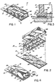
- FIGs. 1-3 A preferred embodiment of a culture slide kit is shown in Figs. 1-3.
- the kit 10 includes a slide 12, a compartment 14 and a bonding element 16 (Fig. 3) adapted to releasably adhere the compartment 14 to the slide 12.
- the compartment 14 has sidewalls 32, an upper extremity or edge 34 and a lower margin 35, and the slide 12 has an upper surface 30.
- the bonding element 16 includes an adhesive 18, as well as the surface region 37A of flange 37 of the compartment lower margin 35 which is in contact with the adhesive 18.
- the adhesive 18 is applied between the flange surface 37A of flange 37 formed on the compartment lower margin 35, and the upper surface 30 of the slide 12.
- the adhesive chemically bonds to both surfaces 37A and 30 to releasably adhere and seal the compartment 14 to the upper surface 30 of the slide 12.
- the bonding element 16 may take a variety of forms as described in detail hereafter. However, a feature common to each of these different bond elements is that the bonding element releasably seals and bonds the compartment to the slide. Another common feature is that, when the compartment is physically separated from the slide, substantially all of the bond element remains with the compartment, leaving the slide upper surface substantially free of any bond element. This second feature results because the bond strength between the bond element and the compartment is greater than the bond strength between the bond element and the slide.
- the bond strength between the bond element and the compartment is the sum of the bond strengths provided by any chemical bond between the adhesive and compartment, and any mechanical bond between the adhesive and compartment.
- the bond strength between the adhesive and the slide also is the sum of any chemical and mechanical bonds therebetween, but most typically, the adhesive-to-slide bonding will be solely of the chemical type.
- the bonding element 16 includes, in addition to the adhesive 18, the lower surface 37A of the flange 37.
- the flange 37 extends both outwardly and inwardly from the lower edges 36 of the lower margin 35 of the sidewalls 32 as best shown in Figs. 2 and 3.
- the flange 37 slightly increases the surface area of the compartment wall lower edges 36, thereby enhancing the releasable seal created by the adhesive 18 disposed between the compartment lower edges 36 and the slide 12.
- the lower edges 36 may have a width equal to the width of the sidewalls 32.
- the adhesive is pressure sensitive. This renders more convenient the assembly of the compartment to the slide during fabrication. While the preferred embodiment incorporates a pressure sensitive adhesive, in which the application of pressure initiates the bonding of the adhesive, other adhesives can be used such as thermally-cured, light-cured, ultrasonically cured, and the like.
- the pressure sensitive adhesive 18 is a multilayer film 38 as shown in Fig. 3.
- the multilayer film 38 includes a polyester carrier film 42 sandwiched between a first acrylic adhesive layer 40 and a second acrylic adhesive layer 44.
- the first acrylic adhesive layer 40 is bonded to the lower edges 36 of the compartment 14, with the second acrylic adhesive layer 44 being the outermost layer, adapted to releasably adhere to the upper surface 30 of the slide 12.
- the thickness of the multilayer film 38 may be varied, and preferably, each of the polyester carrier film 42, first acrylic adhesive layer 40 and second acrylic adhesive layer 44 has a thickness of from about 0.5 mm to about 3 mm.
- the polyester carrier film 42 has a thickness of about 1 mm
- the first acrylic adhesive layer 40 has a thickness of about 3 mm
- the second acrylic adhesive layer 44 has a thickness of about 2 mm.
- the adhesive may be any of a number of different solvent-based acrylic adhesives inert to and impermeable to aqueous solutions and standard tissue culture media, such as the acrylic adhesives available from Coating Sciences, Inc. in Bloomfield, Connecticut under the product designation S268.
- the preferred embodiment further includes a layer 50, preferably exhibiting both hydrophobic and release properties, adhered to the upper surface 30 of the slide 12 in a pattern which underlies the lower margin 35 of the compartment 14 when the compartment 14 is operatively positioned on the upper surface 30 of the slide 12 as shown in Figs. 2 and 3.
- the layer 50 is comprised of a fluorinated hydrocarbon-filled ink, and more preferably, the layer 50 is a polytetrafluoroethylene-filled ink as is available from Cell Line, Inc., in New Field, New Jersey or Erie Scientific Company in Portsmouth, New Hampshire.
- the layer 50, in combination with the upper surface 30 of the slide 12, defines a discrete well or wells 52 as shown in Figs. 2 and 3.
- an inert and impervious hydrophobic layer which also serves as a release layer to assist in providing an adhesive-free slide upon separation of the chamber from the slide.
- an inert and impervious release layer which is not hydrophobic in nature may be used on the upper slide surface underlying the lower margin of the compartment wall.
- the bonding element 16 is able to releasably seal the compartment 14 to either a hydrophobic release layer 50 on the upper surface 30 of the slide 12 or directly to the upper surface 30 of the slide 12 without a hydrophobic release layer 50.
- the bonding element 16 remains bonded to the lower margin 35 of the compartment 14, leaving the hydrophobic release layer 50 or the plain upper surface of the slide 12 virtually free of any adhesive 18.
- the bonding element 16 remains with the compartment 14 because the adhesive 18 exhibits a stronger adhesion to the compartment 14 than to either the layer 50 or plain upper surface 30 of the slide 12.
- the layer 50 remains bonded to the upper surface 30 of the slide 12 because the layer 50 exhibits stronger adhesion to the slide 12 than to the adhesive 18.
- the hydrophobic release layer 50 is preferred because it offers some additional benefits.
- the adhesive 18 creates an effective seal with either the layer 50 or the plain upper surface 30 of the slide 12, the adhesive 18 does not bond quite as strongly to the layer 50 as to the plain upper surface 30 of the slide 12. Therefore, when a slide 12 having the layer 50 is used, the compartment 14 may be removed more easily than when a slide 12 without the layer 50 is used,
- FIGs. 5A-5E A few of the many other possible bonding element 16 configurations are shown in Figs. 5A-5E. These figures are diagrammatic cross-sectional views showing a compartment sidewall 32 sealed and releasably adhered either directly to the upper surface 30 of a slide 12 (Figs. 5A-5E). Note that any of the bonding elements depicted in Figs. 5A-5E may be adhered either directly to the slide upper surface or to a hydrophobic release layer if such a layer is used.
- the bonding element 16 includes an adhesive 18 and a longitudinal channel 90 integral with the compartment lower margin 35.
- the channel 90 has an interior surface 92 made up of two interior sidewalls 98 and a ceiling or upper interior sidewall 100.
- the interior sidewalls 98 have surface irregularities selected from the group of projections and indentations to facilitate the formation of mechanical bonds with the adhesive when it hardens.
- the adhesive 18 is disposed within the channel 90 in an unhardened condition, contacting and forming a chemical bond with the interior surface 92 and the upper surface 30 of the slide 12.
- the unhardened adhesive also forms a mechanical bond with the projections, or serrations, 96 when the adhesive hardens.
- a mechanical bond is created between the indentations, or grooves, 102 in the interior sidewalls 98 of interior channel surface 92 and adhesive 103 which penetrates the grooves.
- the mechanical bond between adhesive 18 and interior surface 92 is created by channel wall projections 104 in the interior sidewalls 98 which extend into the adhesive 18 and are gripped thereby when the adhesive hardens.
- Fig. 5D also shows a chemical and mechanical bond between the interior channel 90 formed in the margin 35 of the chamber wall 32 and the adhesive 18.
- the mechanical bond between adhesive 18 and channel 90 is created by the formation of a dovetail groove 106 having a reduced neck 106A which serves to grip the adhesive 18 once it hardens.
- the upwardly and outwardly sloping sidewalls create indentations relative to the necked portion 106A.
- the chemical bond between the adhesive 18 and channel 90 occurs at the interface between them, namely, at interior surface 92.
- Fig. 5E shows an example of a bonding element 16 using solely chemical bonding.
- the bonding element 16 includes an adhesive 18 and a V-shaped edge 108 integral with the compartment lower margin 35.
- the adhesive 18 chemically bonds with the V-shaped surface 108A of the V-shaped edge 108 and with the underlying surface 30A of slide 12.
- the adhesive 18 forms a greater chemical bond strength with the V-shaped edge surface 108A than with the lesser surface area upper slide surface 30A, the adhesive remains adhered to the lower margin 35 of the chamber wall, leaving the slide surface free of adhesive residue.
- the greater bond strength may result from the adhesive 18 having a greater surface area of contact with the V-shaped edge 108 than with the slide upper surface 30, and/or the adhesive 18 having a greater chemical bonding affinity for the material used in the compartment 14 than in the slide 12.
- the adhesive 18 can be inserted into the channels 90 of the embodiments of Figs. 5A-5D in any desired manner, such as shown in U.S. Pat. No. 3,726,764, in the name of F. K. White.
- the compartment 14 made according to the principles of the inventive culture slide kit may come in several different forms and have different features.
- the compartment 14 may have a single chamber (Fig. 4) or multiple chambers (Figs. 1 and 2). Multiple chambers typically are created by having interior sidewalls 62 within the compartment 14 as shown in Figs. 1 and 2.
- the compartment 14 also may include a tab 64, providing the user with a convenient place to grasp the compartment 14 when removing the compartment 14 from the slide 12 (Fig. 2).
- the top surface of the compartment 14 may be open, in which case a removable cover 66 may be provided as shown in Figs. 1 and 2.
- the removable cover 66 may have a grasping tab on a cover end-wall (not shown), similar to the tab 64 on the compartment 14, instead of the cover handle shown in Figs. 1 and 2. This grasping tab may be used to assist the user in removing the compartment 14 while the cover 66 is on the compartment 14.
- the compartment 14 has a top wall 67 with sidewalls 32 depending therefrom and having lower edges 36.
- the top wall 67 and the upper extremity of the sidewalls 32 are integral and collectively define a covered compartment 14 having an open bottom 68.
- the compartment 14 is provided with an access port 69 extending outwardly from one of the sidewalls 32 as shown in Fig. 4.
- the access port 69 may be sealed using a device such as a closure cap 70 having threads (not shown) which engage threads 74 on the access port 69 (Fig. 4).
- the compartment 14 may be made of any of a number of different plastics or glass which are inert to and impermeable to aqueous solutions and standard tissue culture media.
- the compartment 14 is formed from a transparent thermoplastic, such as polystyrene, polypropylene, celluloid, polymethylmethacrylate, polymethacrylate and the like. More preferably, the compartment 14 is made of polystyrene.
- the slide 12 may be made of a glass or plastic inert to and impermeable to aqueous solutions and standard tissue culture media. Preferably, soda glass is used. If desired, the slide 12 may be a slide 12 having a frosted coating 80 on an end of the upper surface 30, as is available from Erie Scientific Company, Portsmouth, New Hampshire. The frosted coating allows for easy, permanent labeling of the slide.
- compartment and cover could be provided with a complementary projection and recess (not shown), respectively, to enable the cover to be properly seated and re-seated on the compartment in only one orientation, which may be particularly useful for compartments having multiple chambers.
- a complementary projection and recess not shown
- any material from an individual chamber or any material derived from the contents of that chamber is deposited on the corresponding inside surface of the cover (for example, a virus, bacteria, condensate, culture, etc.), it is not possible to re-seat the cover on the compartment in an orientation different than that which existed prior to removing the cover, which if permitted to occur could contaminate a given culture with material from another culture.
Landscapes
- Engineering & Computer Science (AREA)
- Health & Medical Sciences (AREA)
- Chemical & Material Sciences (AREA)
- Zoology (AREA)
- Life Sciences & Earth Sciences (AREA)
- Bioinformatics & Cheminformatics (AREA)
- Organic Chemistry (AREA)
- Wood Science & Technology (AREA)
- Mechanical Engineering (AREA)
- General Health & Medical Sciences (AREA)
- Biochemistry (AREA)
- Microbiology (AREA)
- General Engineering & Computer Science (AREA)
- Biotechnology (AREA)
- Genetics & Genomics (AREA)
- Biomedical Technology (AREA)
- Sustainable Development (AREA)
- Clinical Laboratory Science (AREA)
- Analytical Chemistry (AREA)
- Physics & Mathematics (AREA)
- Immunology (AREA)
- Hematology (AREA)
- General Physics & Mathematics (AREA)
- Optics & Photonics (AREA)
- Chemical Kinetics & Catalysis (AREA)
- Apparatus Associated With Microorganisms And Enzymes (AREA)
- Materials For Medical Uses (AREA)
Claims (22)
- Züchtungsträgersatz (10), der folgendes aufweist:(a) einen Träger (12) mit einer oberen Oberfläche (30);(b) ein Fach (14) mit Seitenwänden (32) mit einer oberen Extremität (34) und einem unteren Rand (35), wobei das Fach betrieblich auf der oberen Oberfläche des Trägers angeordnet werden kann; und(c) ein Bindeelement (16), das die obere Oberfläche (30) des Trägers (12) an den unteren Rand (35) der Seitenwände (32) abdichten und lösbar binden kann, wobei das Bindeelement (16) an dem unteren Rand (35) gebunden bleibt, wenn das Fach (14) und der Träger 912) physikalisch getrennt werden, was die obere Oberfläche (30) des Trägers (12) im wesentlichen von dem Bindeelement nach der Trennung frei halt, dadurch gekennzeichnet, dass das Bindeelement (16) einen Acrylklebstoff (18) einschließt.
- Züchtungsträgersatz nach Anspruch 1, in dem der Klebstoff ein Vielschichtfilm (38) ist, der folgendes aufweist:(a) einen Polyesterträgerfilm (42);(b) eine erste Acrylklebstoffschicht (40) auf der Seite des Polyesterträgerfilms (42), die den unteren Rand (35) der Fachseitenwände (32) kontaktiert; und(c) eine zweite Acrylklebstoffschicht (44) auf der anderen Seite des Polyesterträgerfilms (42).
- Züchtungsträgersatz nach Anspruch 2, in dem die Acrylklebstoffschichten (40, 44) aus einem auf einem Lösungsmittel beruhenden Acrylstoff hergestellt sind.
- Züchtungsträgersatz nach entweder Anspruch 2 oder Anspruch 3, in dem der Polyesterträgerfilm (42) eine Dicke von 0,5 mm bis 3 mm hat, vorzugsweise 1 mm, die erste Acrylklebstoffschicht (40) eine Dicke von 0,5 bis 3 mm hat, vorzugsweise 3 mm, und die zweite Acrylklebstoffschicht eine Dicke von 0,5 bis 3 mm hat, vorzugsweise 2 mm.
- Züchtungsträgersatz nach Anspruch 1, in dem das Bindeelement (16) einen härtbaren Acrylklebstoff (18) in Kontakt mit einer Oberflächenunregelmäßigkeit (96, 102, 104, 106) auf dem unteren Rand (35) der Fachseitenwand einschließt, um eine mechanische Bindung zwischen dem unteren Rand (35) der Fachseitenwand und dem Klebstoff (18) festzusetzen, wenn der Klebstoff härtet.
- Züchtungsträgersatz nach Anspruch 5, in dem die Oberflächenunregelmäßigkeit wenigstens eine Nut (102, 106) aufweist, die von Klebstoff durchdrungen ist, um eine mechanische Bindung dazwischen festzusetzen, wenn der Klebstoff härtet, oder wenigstens einen Vorsprung (96, 104), der von Klebstoff umgeben ist, um eine mechanische Bindung dazwischen festzusetzen, wenn der Klebstoff härtet.
- Züchtungsträgersatz nach Anspruch 5, in dem die Oberflächenunregelmäßigkeit wenigstens einen Vorsprung (104), eine Verzahnung (96), eine Einkerbung (102) oder eine Nut (102, 106) aufweist.
- Züchtungsträgersatz nach einem der Ansprüche 5 bis 7, in dem der Klebstoff (18) in einem längs verlaufenden Kanal (90) integral mit dem unteren Rand (35) und in Kontakt mit der inneren Oberfläche (92) des Kanals angeordnet ist.
- Züchtungsträgersatz nach Anspruch 8, in dem die innere Oberfläche (92) des Kanals eine Schwalbenschwanznut (106) mit einem gekragten Gebiet (106A) in der Nähe der oberen Oberfläche des Trägers einschließt, um eine mechanische Bindung zwischen der Nut (106) und dem gehärteten Klebstoff in der Nut festzusetzen.
- Züchtungsträgersatz nach einem der Ansprüche 5 bis 9, in dem die Affinität des Klebstoffs (18) für den unteren Rand (35) der Fachseitenwand im wesentlichen geringer als seine Affinität für den Träger (12) ist, wobei die Bindung zwischen dem Klebstoff (18) und dem unteren Rand (35) der Fachseitenwand im wesentlichen nur eine mechanische Bindung ist, wobei die Bindungsstärke der mechanischen Bindung zwischen dem Klebstoff und dem unteren Rand der Fachseitenwand die Bindungsstärke der chemischen Bindung zwischen dem Klebstoff (18) und dem Träger (12) überschreitet.
- Züchtungsträgersatz nach einem der Ansprüche 1 bis 9, in dem der Klebstoff (18) den unteren Rand (35) der Fachseitenwände lösbar an die obere Oberfläche (30) des Trägers (12) anhaften kann, wobei der Klebstoff (18) eine stärkere Haftung an den unteren Rand (35) als an die obere Oberfläche des Trägers (12) zeigt, wobei Trennung des Fachs (14) von dem Träger (12) im wesentlichen den ganzen Klebstoff (18) von dem Träger (12) wirksam entfernt.
- Züchtungsträgersatz nach einem der Ansprüche 1 bis 9, der weiterhin eine Lösungsschicht (50) aufweist, die zwischen dem Bindeelement (16) und der oberen Oberfläche (30) des Trägers (12) angeordnet ist und an die obere Oberfläche (30) des Trägers in einem Muster geklebt ist, das unter dem unteren Rand (35) der Fachseitenwände liegt, wenn das Fach (14) betrieblich auf der oberen Oberfläche (30) des Trägers angeordnet ist, wobei das Bindeelement (16) eine stärkere Bindung zu dem unteren Rand (35) der Fachseitenwand als zu der Lösungsschicht (50) zeigt, wobei die Lösungsschicht (50) eine stärkere Anhaftung an die obere Oberfläche (30) des Trägers als an das Bindeelement zeigt (16), wobei Trennung des Fachs (14) von dem Träger (12) im wesentlichen das ganze Bindeelement (16) von der Lösungsschicht (50) wirksam entfernt, wobei im wesentlichen die ganze Lösungsschicht (50) an dem Träger (12) haften bleibt.
- Züchtungsträgersatz nach Anspruch 12, in dem der Träger (12), das Fach (14), der Klebstoff (18) und die Lösungsschicht (50) träge und undurchlässig gegenüber wässrigen Lösungen und Standardgewebezüchtungsmedien sind.
- Züchtungsträgersatz nach Anspruch 12 oder Anspruch 13, in dem die Lösungsschicht (50) eine hydrophobe Schicht ist, die vorzugsweise fluorinierte mit Kohlenwasserstoff gefüllte Tinte aufweist.
- Züchtungsträgersatz nach Anspruch 1, in dem der Klebstoff (18) mit der oberen Oberfläche (30) des Trägers (12) in Kontakt ist und in dem der untere Rand (35) der Fachseitenwand eine Oberfläche (108A) frei von mechanischen bindungsbildenden Oberflächenunregelmäßigkeiten hat, die mit dem Klebstoff (18) in Kontakt ist, wobei das Oberflächengebiet des unteren Randgebiets (108A) der Fachseitenwand in Kontakt mit dem Klebstoff größer als das Oberflächengebiet der oberen Trägeroberfläche (30) ist, das mit dem Klebstoff in Kontakt ist, und in dem der Fachseitenwandrand (35) aus einem Material hergestellt ist, das eine geringere Affinität für den Klebstoff (18) zeigt als von dem Träger (12) gezeigt wird, wobei die Bindung zwischen dem Klebstoff (18) und dem unteren Rand (35) der Fachseitenwand im wesentlichen nur eine chemische Bindung ist, und dennoch, wenn der Träger (12) und das Fach (14) getrennt werden, dann bleibt der Klebstoff (18) an dem unteren Rand (35) haften und löst sich von dem Träger (12).
- Züchtungsträgersatz nach einem vorhergehenden Anspruch, der weiterhin einen Deckel (66) aufweist, der über die obere Extremität (34) des Fachs passen kann.
- Verfahren zum Herstellen eines Züchtungsträgersatzes, das die folgenden Schritte aufweist:(a) Liefern eines Mikroskopträgers (12) mit einer oberen Oberfläche (30);(b) Liefern eines Fachs (14) mit Seitenwänden (32) mit einer oberen Extremität (34) und einem unteren Rand (35), wobei das Fach (14) betrieblich auf der oberen Oberfläche (30) des Trägers angeordnet werden kann; und(c) Liefern eines Bindeelements (16) zwischen der oberen Oberfläche (30) des Trägers und dem unteren Rand (35) der Fachseitenwände, um die obere Oberfläche (30) des Trägers an den unteren Rand (35) der Fachseitenwände abzudichten und lösbar zu binden, wobei das Bindeelement (16) an dem unteren Rand (35) gebunden bleibt, wenn das Fach (14) und der Träger (12) physikalisch getrennt werden, was die obere Oberfläche (30) des Trägers im wesentlichen von dem Bindeelement (18) nach der Trennung frei hält, dadurch gekennzeichnet, dass das Bindeelement (16) einen Acrylklebstoff (18) einschließt.
- Verfahren zum Herstellen eines Züchtungsträgersatzes nach Anspruch 17, in dem der Klebstoff (18) ein härtbarer Klebstoff ist, und in dem das Verfahren weiterhin aufweist, eine Oberflächenunregelmäßigkeit (96, 102, 104, 106) in dem unteren Rand (35) des Fachs zu liefern, die den Klebstoff in einem nicht gehärteten Zustand kontaktieren können, und nicht gehärteten Klebstoff in Kontakt mit der Oberflächenunregelmäßigkeit (96, 102, 104, 106) einzuführen, um eine mechanische Bindung mit der Oberflächenunregelmäßigkeit zu bilden, wenn der Klebstoff (18) hart wird.
- Verfahren zum Herstellen eines Züchtungsträgersatzes nach entweder Anspruch 17 oder Anspruch 18, in dem der Bindeelementlieferungsschritt einschließt, den Klebstoff zwischen dem unteren Rand (35) der Fachseitenwände und der oberen Oberfläche (30) des Trägers zu liefern, um den unteren Rand der Fachseitenwände an die obere Oberfläche des Trägers abzudichten und lösbar zu kleben, wobei der Klebstoff (18) eine stärkere Anhaftung an den unteren Rand (35) der Fachseitenwand (35) als an die obere Oberfläche (30) des Trägers zeigt, wobei Trennung des Fachs (14) von dem Träger (12) im wesentlichen den ganzen Klebstoff wirksam von dem Träger (12) entfernt.
- Verfahren zum Herstellen eines Züchtungsträgersatzes nach entweder Anspruch 17 oder Anspruch 18, das vor dem Dichtungs- und Bindeschritt den weiteren Schritt einschließt, eine Lösungsschicht (50) an die obere Oberfläche (30) des Trägers in einem Muster zu kleben, das unter dem unteren Rand (35) der Fachseitenwände liegt, wenn das Fach (14) betrieblich auf der oberen Oberfläche des Trägers angeordnet ist, das Bindeelement (18) eine stärkere Bindung zu dem unteren Rand (35) der Fachseitenwand liefert als zu der Lösungsschicht (50), die Lösungsschicht (50) eine stärkere Haftung an die obere Oberfläche (30) des Trägers als an das Bindeelement (16) zeigt, wobei Trennung des Fachs (14) von dem Träger (12) im wesentlichen das ganze Bindeelement (16) wirksam von dem Träger (12) entfernt, wobei im wesentlichen die ganze Lösungsschicht (50) an dem Träger haften bleibt.
- Verfahren zum Herstellen eines Züchtungsträgersatzes nach Anspruch 17, in dem der Fachlieferungsschritt einschließt, ein Fach (14) zu liefern, in dem der untere Rand (35) der Fachseitenwand eine Oberfläche (106A) hat, die von mechanischen Bindebildungsoberflächenunregelmäßigkeiten frei ist, die mit dem Klebstoff (18) in Kontakt ist, wobei das Oberflächengebiet der unteren Randoberfläche (106A) der Fachseitenwand in Kontakt mit dem Klebstoff (18) größer als das Oberflächengebiet der oberen Trägeroberfläche (30) ist, die mit dem Klebstoff in Kontakt ist und den unteren Rand (35) der Fachseitenwand eines Materials herstellt, das eine geringere Affinität für den Klebstoff (18) zeigt als von dem Träger (12) gezeigt wird, wobei die Bindung zischen dem Klebstoff (18) und dem unteren Rand (35) der Fachseitenwand im wesentlichen nur eine chemische Bindung ist, und dennoch, wenn der Träger (12) und das Fach (14) getrennt werden, bleibt der Klebstoff an dem unteren Rand (35) geklebt und löst sich von dem Träger.
- Verfahren zum Herstellen eines Züchtungsträgersatzes nach einem der Ansprüche 17 bis 21, das weiterhin den Schritt aufweist, einen Deckel (66) über die obere Extremität (34) des Fachs zu bringen.
Applications Claiming Priority (2)
| Application Number | Priority Date | Filing Date | Title |
|---|---|---|---|
| US08/238,312 US5571721A (en) | 1994-05-05 | 1994-05-05 | Improved biological culture slide and method of making same |
| US238312 | 1994-05-05 |
Publications (3)
| Publication Number | Publication Date |
|---|---|
| EP0681024A2 EP0681024A2 (de) | 1995-11-08 |
| EP0681024A3 EP0681024A3 (de) | 1998-06-17 |
| EP0681024B1 true EP0681024B1 (de) | 2003-03-26 |
Family
ID=22897357
Family Applications (1)
| Application Number | Title | Priority Date | Filing Date |
|---|---|---|---|
| EP95302871A Expired - Lifetime EP0681024B1 (de) | 1994-05-05 | 1995-04-27 | Verbesserter Träger für biologische Züchtung und Verfahren zur Herstellung |
Country Status (4)
| Country | Link |
|---|---|
| US (1) | US5571721A (de) |
| EP (1) | EP0681024B1 (de) |
| JP (1) | JPH08154661A (de) |
| DE (1) | DE69530022T2 (de) |
Families Citing this family (77)
| Publication number | Priority date | Publication date | Assignee | Title |
|---|---|---|---|---|
| US6022689A (en) * | 1995-04-07 | 2000-02-08 | University Of New Mexico | Situ hybridization slide processes |
| US5518925A (en) * | 1995-06-06 | 1996-05-21 | Becton Dickinson Co | Culture slide assembly |
| US5605813A (en) * | 1995-06-06 | 1997-02-25 | Becton, Dickinson And Company | Culture slide assembly |
| US5618731A (en) * | 1995-06-06 | 1997-04-08 | Becton, Dickinson And Company | Culture slide assembly |
| DE19524795C2 (de) * | 1995-07-07 | 1997-06-12 | Danfoss As | Chemische Analysevorrichtung |
| USD413390S (en) | 1995-09-28 | 1999-08-31 | Cytocell Limited | Carrier for samples or reagents |
| USD436668S1 (en) | 1996-03-27 | 2001-01-23 | Cytocell Limited | Carrier for samples or reagents |
| US5784193A (en) * | 1996-06-28 | 1998-07-21 | Ferguson; Gary W. | Microscope slide with removable layer and method |
| US5939251A (en) * | 1996-07-12 | 1999-08-17 | Hu; Min | Apparatus and method for simplifying the processes in creating a sealed space on slides to conduct molecular biological reactions therein |
| US5817509A (en) * | 1997-03-19 | 1998-10-06 | Becton Dickinson And Company | Culture vessel assembly |
| US5863792A (en) * | 1997-03-19 | 1999-01-26 | Becton Dickson And Company | Culture vessel assembly |
| US5780294A (en) * | 1997-03-19 | 1998-07-14 | Becton Dickinson And Company | Culture vessel assembly |
| US5882922A (en) * | 1997-03-19 | 1999-03-16 | Becton Dickinson And Company | Culture vessel assembly |
| US6052224A (en) * | 1997-03-21 | 2000-04-18 | Northern Edge Associates | Microscope slide system and method of use |
| US5928858A (en) * | 1997-07-18 | 1999-07-27 | Chao; David M. | Petri dish with removable location markings and method of making the same |
| US6037168A (en) * | 1997-12-31 | 2000-03-14 | Cytonix Corporation | Microbiological assembly comprising resealable closure means |
| US8192994B2 (en) | 1998-02-10 | 2012-06-05 | Angros Lee H | Method of applying a biological specimen to an analytic plate |
| US6818451B2 (en) * | 1998-02-10 | 2004-11-16 | Lee H. Angros | Analytic plate with containment border |
| US6713304B2 (en) * | 1998-02-10 | 2004-03-30 | Lee H. Angros | Method of forming a containment border on an analytic plate |
| USD420746S (en) * | 1998-05-16 | 2000-02-15 | Cytocell Limited | Carrier for samples or reagents |
| USD420745S (en) * | 1998-05-16 | 2000-02-15 | Cytocell Limited | Carrier for samples or reagents |
| USD420452S (en) * | 1998-05-16 | 2000-02-08 | Cytocell Limited | Carrier for samples or reagents |
| USD418228S (en) * | 1998-09-03 | 1999-12-28 | Harry Fisch | Microscope slide assembly |
| USD431300S (en) * | 1999-09-27 | 2000-09-26 | Harry Fisch | Microscope slide assembly |
| US7005029B2 (en) * | 1999-10-26 | 2006-02-28 | Nalge Nunc International Corporation | Method of making a multi-well test plate having adhesively secured transparent bottom panel |
| US6642046B1 (en) * | 1999-12-09 | 2003-11-04 | Motorola, Inc. | Method and apparatus for performing biological reactions on a substrate surface |
| US20020187485A1 (en) * | 2000-10-25 | 2002-12-12 | Jakobsen Mogens Hausteen | Open substrate platforms suitable for analysis of biomolecules |
| US7223363B2 (en) | 2001-03-09 | 2007-05-29 | Biomicro Systems, Inc. | Method and system for microfluidic interfacing to arrays |
| US7063979B2 (en) * | 2001-06-13 | 2006-06-20 | Grace Bio Labs., Inc. | Interface between substrates having microarrays and microtiter plates |
| USD473318S1 (en) | 2001-07-26 | 2003-04-15 | Biocrystal, Ltd. | Cell management device |
| US6682702B2 (en) * | 2001-08-24 | 2004-01-27 | Agilent Technologies, Inc. | Apparatus and method for simultaneously conducting multiple chemical reactions |
| WO2003032801A2 (en) * | 2001-10-18 | 2003-04-24 | Third Millennium Engineering Llc | Artificial intervertebral disc having a spider spring force restoring element |
| US6939032B2 (en) * | 2001-10-25 | 2005-09-06 | Erie Scientific Company | Cover slip mixing apparatus |
| US7943093B2 (en) * | 2001-12-12 | 2011-05-17 | Erie Scientific Company | Cover slip |
| US7160514B2 (en) * | 2001-12-18 | 2007-01-09 | Erie Scientific Company | Slide case with removable rack |
| WO2003053586A1 (en) * | 2001-12-19 | 2003-07-03 | Affymetrix, Inc. | Array plates and method for constructing array plates |
| US7736594B1 (en) | 2002-01-22 | 2010-06-15 | Grace Bio-Labs, Inc. | Reaction surface array diagnostic apparatus |
| US7731909B1 (en) | 2002-01-22 | 2010-06-08 | Grace Bio-Labs, Inc. | Reaction surface array diagnostic apparatus |
| US7163823B2 (en) * | 2002-01-28 | 2007-01-16 | Nanosphere, Inc. | DNA hybridization device and method |
| KR100434452B1 (ko) * | 2002-03-05 | 2004-06-04 | 한국생명공학연구원 | 포유동물 세포를 슬라이드글래스의 미세배양조건 하에배양할 수 있는 킷트 및 이의 제조방법 |
| US7919308B2 (en) * | 2002-06-14 | 2011-04-05 | Agilent Technologies, Inc. | Form in place gaskets for assays |
| US20030235518A1 (en) * | 2002-06-21 | 2003-12-25 | Shea Laurence R. | Array assay devices and methods of using the same |
| US20040214313A1 (en) * | 2003-04-28 | 2004-10-28 | Weihua Zhang | Cell interaction culture system and uses thereof |
| DE112004001121T5 (de) * | 2003-06-25 | 2006-05-04 | Waters Investments Ltd., New Castle | Vorrichtung zur Verhinderung der Kreuzverunreinigung in einer Plattform und Herstellungsverfahren |
| CN1289904C (zh) | 2003-08-01 | 2006-12-13 | 博奥生物有限公司 | 一种微阵列反应装置及其应用 |
| DE10340473B4 (de) * | 2003-09-03 | 2007-08-23 | Eppendorf Ag | Abdeckung einer Hybridisierungskammer |
| US20050173059A1 (en) * | 2004-02-11 | 2005-08-11 | Nalge Nunc International Corporation | Methods of making a multi-well test plate having an adhesively secured transparent bottom panel |
| US8034306B1 (en) | 2004-02-20 | 2011-10-11 | Grace Bio-Labs, Inc. | Reaction surface array diagnostic apparatus including a flexible microtitre plate |
| WO2006019836A1 (en) * | 2004-07-22 | 2006-02-23 | Corning Incorporated | Culture flask |
| WO2006069314A1 (en) * | 2004-12-22 | 2006-06-29 | Ge Healthcare Bio-Sciences Ab | Reaction chamber |
| CA2604541C (en) * | 2005-04-15 | 2018-01-16 | Lee H. Angros | Analytic substrate coating apparatus and method |
| US20100073766A1 (en) * | 2005-10-26 | 2010-03-25 | Angros Lee H | Microscope slide testing and identification assembly |
| US20100072272A1 (en) * | 2005-10-26 | 2010-03-25 | Angros Lee H | Microscope slide coverslip and uses thereof |
| US20080056952A1 (en) * | 2006-08-25 | 2008-03-06 | Angros Lee H | Analytic plates with markable portions and methods of use |
| USD569990S1 (en) * | 2006-09-28 | 2008-05-27 | Millennium Sciences | Microscope slide assembly |
| US9751084B2 (en) * | 2008-10-28 | 2017-09-05 | Emd Millipore Corporation | Biological culture assembly |
| US8501122B2 (en) | 2009-12-08 | 2013-08-06 | Affymetrix, Inc. | Manufacturing and processing polymer arrays |
| USD720469S1 (en) * | 2013-03-07 | 2014-12-30 | Viacyte, Inc. | Cell encapsulation device |
| TWI512292B (zh) * | 2014-09-04 | 2015-12-11 | Taiwan Green Point Entpr Co | 薄膜式生物晶片之製作方法 |
| US10077420B2 (en) * | 2014-12-02 | 2018-09-18 | Histogenics Corporation | Cell and tissue culture container |
| JP6179682B2 (ja) * | 2015-01-22 | 2017-08-16 | 株式会社村田製作所 | 空隙配置構造体およびその製造方法 |
| CN107045190A (zh) * | 2016-02-05 | 2017-08-15 | 亿观生物科技股份有限公司 | 样品承载模块与可携式显微镜装置 |
| EP3203293B1 (de) * | 2016-02-05 | 2024-04-24 | Aidmics Biotechnology Co., Ltd. | Probenträgermodul und tragbares mikroskop damit |
| US10288869B2 (en) * | 2016-02-05 | 2019-05-14 | Aidmics Biotechnology Co., Ltd. | Reflecting microscope module and reflecting microscope device |
| EP3203294A1 (de) * | 2016-02-05 | 2017-08-09 | Aidmics Biotechnology Co., Ltd. | Probenklebeelement, probeträgermodul und tragbare mikroskopvorrichtung damit |
| EP3454024A4 (de) * | 2016-03-31 | 2019-12-18 | Dai Nippon Printing Co., Ltd. | Transmissionsfarbkalibriertabelle und kalibrierungsschieberglas |
| US11186818B2 (en) * | 2017-02-27 | 2021-11-30 | Panasonic Intellectual Property Management Co., Ltd. | Culture medium and method for producing culture medium |
| US10247724B1 (en) * | 2017-09-28 | 2019-04-02 | Autobiologic Inc. | Optically clear sealable petri dish bioreactor |
| DE102018000123A1 (de) | 2018-01-09 | 2019-07-11 | Stephan Kniest | Zusammengesetztes Behältnis zur Aufnahme von Kulturen und Nährmedien |
| USD879997S1 (en) * | 2018-09-28 | 2020-03-31 | Harry Fisch | Microscope slide assembly |
| USD879998S1 (en) * | 2018-09-28 | 2020-03-31 | Harry Fisch | Microscope slide assembly |
| USD874019S1 (en) * | 2018-09-28 | 2020-01-28 | Harry Fisch | Microscope slide assembly |
| USD879996S1 (en) * | 2018-09-28 | 2020-03-31 | Harry Fisch | Microscope slide assembly |
| USD876666S1 (en) * | 2018-10-04 | 2020-02-25 | Harry Fisch | Microscope slide assembly |
| US11633741B2 (en) * | 2019-03-19 | 2023-04-25 | Miltenyi Biotec B.V. & Co. KG | Slide chamber |
| EP4197753A1 (de) * | 2021-12-15 | 2023-06-21 | BAE SYSTEMS plc | Hybridgelenk |
| US20240416593A1 (en) * | 2021-12-15 | 2024-12-19 | Bae Systems Plc | Hybrid joint |
Family Cites Families (8)
| Publication number | Priority date | Publication date | Assignee | Title |
|---|---|---|---|---|
| US3745091A (en) * | 1970-11-18 | 1973-07-10 | Miles Lab | Biological reaction chamber apparatus |
| US3726764A (en) * | 1971-08-06 | 1973-04-10 | Miles Lab | Microbiological chamber apparatus |
| US3726767A (en) * | 1971-08-27 | 1973-04-10 | Miles Lab | Microbiological reaction chamber apparatus |
| US3883398A (en) * | 1973-05-07 | 1975-05-13 | Bellco Glass Inc | Microculture slide chamber |
| DE2902026C3 (de) * | 1979-01-19 | 1981-10-29 | Peters, J. Hinrich, Dr., 5064 Rösrath | Biologisches Gefäß |
| DK153674C (da) * | 1985-03-25 | 1988-12-27 | Nunc As | Fremgangsmaade til fremstilling af en plastbeholder |
| DE8512517U1 (de) * | 1985-04-27 | 1985-06-13 | Hastka, Jan, 6803 Edingen | Einrichtung für zytologische und histologische Untersuchungen von Objektträgerpräparaten |
| US4682890A (en) * | 1985-05-31 | 1987-07-28 | Health Research, Incorporated | Microsample holder and carrier therefor |
-
1994
- 1994-05-05 US US08/238,312 patent/US5571721A/en not_active Expired - Lifetime
-
1995
- 1995-04-27 DE DE69530022T patent/DE69530022T2/de not_active Expired - Lifetime
- 1995-04-27 EP EP95302871A patent/EP0681024B1/de not_active Expired - Lifetime
- 1995-05-02 JP JP7108799A patent/JPH08154661A/ja active Pending
Also Published As
| Publication number | Publication date |
|---|---|
| JPH08154661A (ja) | 1996-06-18 |
| DE69530022T2 (de) | 2004-01-08 |
| EP0681024A2 (de) | 1995-11-08 |
| EP0681024A3 (de) | 1998-06-17 |
| DE69530022D1 (de) | 2003-04-30 |
| US5571721A (en) | 1996-11-05 |
Similar Documents
| Publication | Publication Date | Title |
|---|---|---|
| EP0681024B1 (de) | Verbesserter Träger für biologische Züchtung und Verfahren zur Herstellung | |
| US5721136A (en) | Sealing device for thermal cycling vessels | |
| US9751084B2 (en) | Biological culture assembly | |
| EP1126917B1 (de) | Dichtungsmatte zum verschluss von reagenzröhrchen | |
| US12017226B2 (en) | Sample collection kit including cap having selectively movable sleeve | |
| US20080233015A1 (en) | Device and method for use in analysis | |
| US20020084880A1 (en) | Magnetic sheet assembly for magnetic separation | |
| EP0747474B1 (de) | Zusammengesetzter Objektträger für biologische Züchtung | |
| US10059499B2 (en) | Individual package that can be arranged side-by-side in a row with label strips for a medically tight closure | |
| EP0373667B1 (de) | Sammelröhrchen für Flüssigkeiten | |
| CN102272286A (zh) | 用于从处理装置接纳介质的转移单元和方法 | |
| EP1974818A1 (de) | Vorrichtung und Verfahren zur Verwendung für Analysen | |
| JPH0721502B2 (ja) | 蓋構造物 | |
| US8668878B2 (en) | Reaction vessel for crystallizing a sample from a solution | |
| DE69618384T2 (de) | Zusammengesetzter Objektträger für biologische Züchtung | |
| US20210148796A1 (en) | Cassette for inserting a tissue sample | |
| US8034306B1 (en) | Reaction surface array diagnostic apparatus including a flexible microtitre plate | |
| JP2001212205A (ja) | 柔軟性検体容器 | |
| US20240166411A1 (en) | Film seal assembly and single lid assay cartridge and associated methods | |
| JP7015076B1 (ja) | マイクロプレートシール器具 | |
| JPH0585569A (ja) | 気密性を有する密閉式使い捨て容器 | |
| JPH05254569A (ja) | 気密性を有する密閉式使い捨て容器及びその製造方法 | |
| MXPA01008052A (en) | Laboratory cap and well for hanging-drop crystallization methods |
Legal Events
| Date | Code | Title | Description |
|---|---|---|---|
| PUAI | Public reference made under article 153(3) epc to a published international application that has entered the european phase |
Free format text: ORIGINAL CODE: 0009012 |
|
| AK | Designated contracting states |
Kind code of ref document: A2 Designated state(s): DE FR GB |
|
| PUAL | Search report despatched |
Free format text: ORIGINAL CODE: 0009013 |
|
| AK | Designated contracting states |
Kind code of ref document: A3 Designated state(s): DE FR GB |
|
| 17P | Request for examination filed |
Effective date: 19981015 |
|
| 17Q | First examination report despatched |
Effective date: 20011109 |
|
| GRAH | Despatch of communication of intention to grant a patent |
Free format text: ORIGINAL CODE: EPIDOS IGRA |
|
| GRAH | Despatch of communication of intention to grant a patent |
Free format text: ORIGINAL CODE: EPIDOS IGRA |
|
| GRAA | (expected) grant |
Free format text: ORIGINAL CODE: 0009210 |
|
| AK | Designated contracting states |
Designated state(s): DE FR GB |
|
| REG | Reference to a national code |
Ref country code: GB Ref legal event code: FG4D |
|
| REF | Corresponds to: |
Ref document number: 69530022 Country of ref document: DE Date of ref document: 20030430 Kind code of ref document: P |
|
| ET | Fr: translation filed | ||
| PLBE | No opposition filed within time limit |
Free format text: ORIGINAL CODE: 0009261 |
|
| STAA | Information on the status of an ep patent application or granted ep patent |
Free format text: STATUS: NO OPPOSITION FILED WITHIN TIME LIMIT |
|
| 26N | No opposition filed |
Effective date: 20031230 |
|
| PGFP | Annual fee paid to national office [announced via postgrant information from national office to epo] |
Ref country code: GB Payment date: 20140422 Year of fee payment: 20 |
|
| PGFP | Annual fee paid to national office [announced via postgrant information from national office to epo] |
Ref country code: FR Payment date: 20140422 Year of fee payment: 20 Ref country code: DE Payment date: 20140418 Year of fee payment: 20 |
|
| REG | Reference to a national code |
Ref country code: DE Ref legal event code: R071 Ref document number: 69530022 Country of ref document: DE |
|
| REG | Reference to a national code |
Ref country code: GB Ref legal event code: PE20 Expiry date: 20150426 |
|
| PG25 | Lapsed in a contracting state [announced via postgrant information from national office to epo] |
Ref country code: GB Free format text: LAPSE BECAUSE OF EXPIRATION OF PROTECTION Effective date: 20150426 |