EP0681077A2 - Verriegelungsvorrichtung - Google Patents
Verriegelungsvorrichtung Download PDFInfo
- Publication number
- EP0681077A2 EP0681077A2 EP95303116A EP95303116A EP0681077A2 EP 0681077 A2 EP0681077 A2 EP 0681077A2 EP 95303116 A EP95303116 A EP 95303116A EP 95303116 A EP95303116 A EP 95303116A EP 0681077 A2 EP0681077 A2 EP 0681077A2
- Authority
- EP
- European Patent Office
- Prior art keywords
- latch
- operating
- lock mechanism
- bolt
- gear wheel
- Prior art date
- Legal status (The legal status is an assumption and is not a legal conclusion. Google has not performed a legal analysis and makes no representation as to the accuracy of the status listed.)
- Granted
Links
- 230000007246 mechanism Effects 0.000 title claims abstract description 98
- 238000010276 construction Methods 0.000 description 3
- 241000220317 Rosa Species 0.000 description 1
- 230000004913 activation Effects 0.000 description 1
- 238000007796 conventional method Methods 0.000 description 1
- 238000003780 insertion Methods 0.000 description 1
- 230000037431 insertion Effects 0.000 description 1
- 238000012544 monitoring process Methods 0.000 description 1
Images


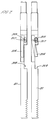
Classifications
-
- E—FIXED CONSTRUCTIONS
- E05—LOCKS; KEYS; WINDOW OR DOOR FITTINGS; SAFES
- E05B—LOCKS; ACCESSORIES THEREFOR; HANDCUFFS
- E05B47/00—Operating or controlling locks or other fastening devices by electric or magnetic means
- E05B47/06—Controlling mechanically-operated bolts by electro-magnetically-operated detents
- E05B47/0603—Controlling mechanically-operated bolts by electro-magnetically-operated detents the detent moving rectilinearly
-
- E—FIXED CONSTRUCTIONS
- E05—LOCKS; KEYS; WINDOW OR DOOR FITTINGS; SAFES
- E05B—LOCKS; ACCESSORIES THEREFOR; HANDCUFFS
- E05B65/00—Locks or fastenings for special use
- E05B65/10—Locks or fastenings for special use for panic or emergency doors
- E05B65/1006—Locks or fastenings for special use for panic or emergency doors of the vertical rod type
-
- E—FIXED CONSTRUCTIONS
- E05—LOCKS; KEYS; WINDOW OR DOOR FITTINGS; SAFES
- E05C—BOLTS OR FASTENING DEVICES FOR WINGS, SPECIALLY FOR DOORS OR WINDOWS
- E05C9/00—Arrangements of simultaneously actuated bolts or other securing devices at well-separated positions on the same wing
- E05C9/04—Arrangements of simultaneously actuated bolts or other securing devices at well-separated positions on the same wing with two sliding bars moved in opposite directions when fastening or unfastening
- E05C9/041—Arrangements of simultaneously actuated bolts or other securing devices at well-separated positions on the same wing with two sliding bars moved in opposite directions when fastening or unfastening with rack and pinion mechanism
-
- E—FIXED CONSTRUCTIONS
- E05—LOCKS; KEYS; WINDOW OR DOOR FITTINGS; SAFES
- E05B—LOCKS; ACCESSORIES THEREFOR; HANDCUFFS
- E05B47/00—Operating or controlling locks or other fastening devices by electric or magnetic means
- E05B2047/0048—Circuits, feeding, monitoring
- E05B2047/0067—Monitoring
-
- E—FIXED CONSTRUCTIONS
- E05—LOCKS; KEYS; WINDOW OR DOOR FITTINGS; SAFES
- E05B—LOCKS; ACCESSORIES THEREFOR; HANDCUFFS
- E05B47/00—Operating or controlling locks or other fastening devices by electric or magnetic means
- E05B47/0001—Operating or controlling locks or other fastening devices by electric or magnetic means with electric actuators; Constructional features thereof
- E05B47/0002—Operating or controlling locks or other fastening devices by electric or magnetic means with electric actuators; Constructional features thereof with electromagnets
-
- Y—GENERAL TAGGING OF NEW TECHNOLOGICAL DEVELOPMENTS; GENERAL TAGGING OF CROSS-SECTIONAL TECHNOLOGIES SPANNING OVER SEVERAL SECTIONS OF THE IPC; TECHNICAL SUBJECTS COVERED BY FORMER USPC CROSS-REFERENCE ART COLLECTIONS [XRACs] AND DIGESTS
- Y10—TECHNICAL SUBJECTS COVERED BY FORMER USPC
- Y10S—TECHNICAL SUBJECTS COVERED BY FORMER USPC CROSS-REFERENCE ART COLLECTIONS [XRACs] AND DIGESTS
- Y10S70/00—Locks
- Y10S70/42—Lost motion devices
-
- Y—GENERAL TAGGING OF NEW TECHNOLOGICAL DEVELOPMENTS; GENERAL TAGGING OF CROSS-SECTIONAL TECHNOLOGIES SPANNING OVER SEVERAL SECTIONS OF THE IPC; TECHNICAL SUBJECTS COVERED BY FORMER USPC CROSS-REFERENCE ART COLLECTIONS [XRACs] AND DIGESTS
- Y10—TECHNICAL SUBJECTS COVERED BY FORMER USPC
- Y10T—TECHNICAL SUBJECTS COVERED BY FORMER US CLASSIFICATION
- Y10T292/00—Closure fasteners
- Y10T292/08—Bolts
- Y10T292/0801—Multiple
- Y10T292/0834—Sliding
- Y10T292/0836—Operating means
- Y10T292/0843—Gear
-
- Y—GENERAL TAGGING OF NEW TECHNOLOGICAL DEVELOPMENTS; GENERAL TAGGING OF CROSS-SECTIONAL TECHNOLOGIES SPANNING OVER SEVERAL SECTIONS OF THE IPC; TECHNICAL SUBJECTS COVERED BY FORMER USPC CROSS-REFERENCE ART COLLECTIONS [XRACs] AND DIGESTS
- Y10—TECHNICAL SUBJECTS COVERED BY FORMER USPC
- Y10T—TECHNICAL SUBJECTS COVERED BY FORMER US CLASSIFICATION
- Y10T70/00—Locks
- Y10T70/50—Special application
- Y10T70/5093—For closures
- Y10T70/5155—Door
- Y10T70/5199—Swinging door
- Y10T70/5226—Combined dead bolt and latching bolt
- Y10T70/5243—Manually dogged latch bolt
Definitions
- the present invention relates to a lock mechanism and more particularly to a lock mechanism which can be latched in an engaged position.
- Locks which provide security on one side and easy and quick operation from the other side are used widely, particularly for doors providing an emergency exit from a building.
- the present invention is directed towards a solution to this problem.
- the present invention provides a lock mechanism comprising at least one bolt member moveable between an engaged and a disengaged position, latch means arranged to prevent movement of at least one said bolt member from said engaged position to said disengaged position, a first operating member for operating said lock mechanism from one side thereof, and operating means for operating said lock mechanism from the other side thereof, wherein said operating means comprises a second operating member and latch release means, said latch means is arranged to be responsive to movement of said first operating member or said latch release means to release said bolt member and allow movement thereof from an engaged position to a disengaged position, and said bolt members are arranged to be moveable between said engaged and disengaged positions in response to movement of said first or second operating members.
- said bolt members are arranged to be directly driven between said engaged and disengaged positions by movement of said first or second operating members.
- the present invention provides a lock mechanism for use on a door hinged in a door frame at a first side, said lock mechanism comprising bolt members moveable between an engaged position in said door frame and a disengaged position, said bolt members being arranged to engage said door frame from at least two of the sides of said door which are not hinged, latch means arranged to prevent movement of at least one said bolt member from said engaged position to said disengaged position, and a latch release arrangement to disengage said latch means and allow movement of said at least one bolt member, said latch release arrangement and said at least one bolt means being arranged to being operable in response to a single movement of an operating member to allow said latch means to be disengaged and said bolt members to be disengaged from said engaged position; and said bolt members being arranged to be directly driven between said engaged and disengaged positions by movement of said operating member.
- a lock mechanism there is preferably included a first operating member for operating to at least one bolt member and said latch release arrangement from one side of said lock mechansim, and operating means for operating said at least one bolt member and said latch release arrangement from the other side of said lock mechanism, said operating means comprising a second operating member and latch release means, said latch release means being arranged to operate said latch release arrangement, and said bolt means being arranged to be moveable between said engaged and said disengaged positions in response to movement of said first or second operating members.
- the lock mechanism which utilises a direct drive mechanism between the operating member, e.g. a handle, and the bolt members provides for positive and visible locking since the position of the operating member will indicate whether the bolt members are properly engaged or not.
- a direct driven bolting arrangement provides for a heavy duty lock mechanism which together with the latching arrangement, which operates when the bolt members are engaged, provides for high security.
- said latch means is arranged to be responsive to an initial movement of said first operating member and said bolt means may not be responsive to said initial movement of said first operating member.
- the latch release means can include key means and/or an electrically operated actuator which allows for remote operation of the latch means.
- said latch means is arranged to engage said at least one bolt member.
- said latch means comprises a first latch arrangement arranged to be responsive to movement of said first operating member to an unlatched state and release said bolt member and the second latch arrangement arranged to be responsive to said latch release means to move to an unlatched state and release said bolt member.
- first and second latch arrangements are preferably arranged to co-operatively prevent movement of said bolt member.
- said latch means is preferably arranged to be disabled when said second latch arrangement is held in an unlatched state by said latch release means.
- the lock mechanism preferably includes bolt member bias means arranged to bias at least one bolt member towards an engaged position.
- the lock mechanism includes bolt member drive means arranged to drive said at least one bolt member between said engaged and disengaged positions.
- the bolt member drive means preferably comprises a first drive gear wheel engaged with a length of a first bolt member and with a length of a first side of a second bolt member, a second drive gear wheel engaged with a length of a second side of said second bolt member with a length of a third bolt member, said first and second drive gear wheels being arranged to rotate in opposite directions in response to movement of said first or second operating members, said first and third bolt members being arranged to be driven in opposed directions by rotation of said drive gear wheels, and said second bolt member being arranged to be driven in a direction generally perpendicularly to said opposed directions.
- This arrangement of gears provides for a strong direct drive mechanism between the operating member and the bolt members.
- said latch means include latch operating means arranged to be responsive to movement of said first operating member to release said at least one bolt member; said latch operating means comprising a latch gear wheel and a latch member, said latch gear wheel being arranged to be responsive to movement of said first operating member to release said latch member from engagement with said bolt member.
- said latch means includes latch operating means arranged to be responsive to movement of said first operating member to release said at least one bolt member, said latch operating means comprising a latch gear wheel and a latch operating member, said latch gear wheel being engaged with a length of said latch operating member and being arranged to rotate in response to movement of said first operating member and drive said latch operating member in a first direction, said latch means including a latch member arranged to be moveable between a latched and an unlatched position, and said latch operating member being connected to said latch member such that movement of said latch operating member in said first direction causes said latch member to move from said latch to said unlatched position.
- said latch gear wheel and said first drive gear wheel are arranged on a common shaft, said latch gear wheel being adapted to receive said first operating member and rotate in response to movement thereof, said first drive gear wheel and said latch gear wheel being connected by lost motion means such that initial motion of said first operating member causes rotation of said latch gear wheel only until the lost motion is taken up whereupon motion of said first operating member causes rotation of said first drive gear wheel.
- said lost motion means comprises at least one pin protruding from one of said latch gear wheel and said first drive gear wheel, and at least one slot provided in the other of said first drive gear wheel or said latch gear wheel to receive said at least one pin.
- a lock mechanism includes latch member bias means arranged to return said latch member to the latched position once the lost motion is given up.
- said latch member bias means may comprise spring means interconnecting said first drive gear wheel and said latch gear wheel.
- said latch release means includes a lock member arranged to be engageable with said bolt member, and a key operable mechanism for operating said lock member.
- said latch release means includes an electrically operated actuator such as a solenoid or remote electrical operation of the latch means.
- Figures 1, 2 and 3 illustrate one embodiment of the present invention which provides a lock mechanism which can be operated from one side using an operating member to unlatch the bolts when they are in the engaged position and to withdraw the bolts to a disengaged position.
- the release of the latch mechanism and the retraction of the bolts occurs by a single simple motion of the operating member.
- This arrangement can be used for a door providing an emergency exit wherein an operating member is provided only on the inside of the door and no operating member is provided on the outside.
- an operating member is provided only on the inside of the door and no operating member is provided on the outside.
- the lock mechanism can be operated simply and quickly by for instance a single push of a release bar, whilst on the outside the lock mechanism is not accessible.
- the lock mechanism provides for security since not only is the lock mechanism inaccessible, but also the bolt members which engage the door frame are resistant to end pressure to retract them from the engaged position.
- the simple lock mechanism provides the required security without compromising on the necessary safety element.
- FIG 1 the cover plate 1 which is shown in Figure 2 is removed to show the construction of the lock mechanism in detail.
- Three bolt members 2, 3 and 4 project from the housing 5 and are capable of translational motion in and out of the housing 5. Two of the bolt members 2 and 4 move in opposite directions whilst the third bolt member 3 moves in a direction which is generally perpendicular to the opposed directions.
- the bolt members 2, 3 and 4 are shown in Figure 1 to have a fairly short length. However, the lengths of the bolt members 2, 3 and 4 will depend on the door to which the lock mechanism is designed to fit. Normally, the bolt members 2, 3 and 4 will be much longer and will be arranged to engage the top and bottom and one side of the door frame. The remaining side of the door frame is the side on which the door is hinged. Such an arrangement of bolts is a conventional method of providing security and provides a high resistance to a physical attack.
- a first drive gear wheel 6 which has a portion 6a which fits into a hole in the cover 1 to allow rotation of the first drive gear wheel.
- Cogs of the first drive gear wheel engage cogs provided along one side of a length of the bolt members 3 and 4 which are arranged generally perpendicularly.
- a second drive gear wheel 7 is provided space from the first drive gear wheel 6 and has a portion 7a which fits in a hole in the cover 1, a portion 7b which fits in a hole in a housing 5 to allow rotation of the second drive gear wheel 7.
- Cogs of the second drive gear wheel 7 are engaged with cogs provided along a length of the second side of the bolt member 3 and along a side of the bolt member 2.
- the first and second drive gear wheels are arranged to rotate in opposite directions and the rotation thereof causes translational motion of the bolt members 2, 3 and 4.
- the bolt members 2, 3 and 4 are biased in an engaged position by a spring 8 and a spring link member 9 which has cogs provided along a length to engage with the cogs of the first drive gear wheel 6.
- the first drive gear wheel 6 is provided with offset slots 10 to receive pins 11 of a latch gear wheel 12.
- the latch gear wheel 12 has a portion 12a which fits into a hole in the housing 5 to allow rotation thereof.
- the first drive gear wheel 6 and the latch gear wheel 12 are mounted to have the same axis of rotation and support each other in the centre.
- the latch gear wheel 12 is provided with a splined recess 13 which is designed to receive an operating member such as a handle for rotation of the latch gear wheel 12.
- a decorative plate 14 together with a rose plate 15 to support the handle and allow its rotation and operation of the lock mechanism.
- the pins 11 of the latch gear wheel 12 are held in their position against the anticlockwise side of the slot 10 in the first drive gear wheel 6 by bias means provided in the form of springs 16 interconnecting the first drive gear wheel 6 and the latch gear wheel 12.
- Cogs of the latch gear wheel 12 engage cogs provided on a latch member 17.
- the latch member 17 has been extended to the right to prevent movement of the spring link member 9.
- the bolt members 2, 3 and 4 can be retracted to the disengaged position it is necessary to move the latch member 17 to the left to allow the spring link member 9 and hence the drive gear wheels 6 and 7 and the bolt members 2, 3 and 4 to move.
- the movement of the latch member is achieved by rotation of the operating member and thus the rotation of the latch gear wheel 12.
- the latch gear wheel rotates clockwise the latch gear wheel 17 is moved to the left.
- the pins 11 of latch gear wheel 12 move clockwise within the slots 10 of the first drive gear wheel until they make contact with the sides of the slots in the clockwise direction.
- the latch member 17 has moved far enough left to be out of the way of the spring link member 9, i.e. it is in the unlatched position, and thus further rotation of the operating member causes the latch gear wheel 12 to drive the first drive gear wheel 6 in the clockwise direction against the spring force of the spring 8 to retract the bolt members 2, 3 and 4.
- the embodiment described hereinabove provides for a simple lock mechanism whereby no access is required to the mechanism from one side, i.e. outside.
- a lock mechanism can be used for a simple door forming an emergency exit.
- Figures 4 to 7 illustrate a second embodiment of the present invention which provides the same simplistic single operation by an operating member on the one side but also allows for the operation of the lock mechanism from the other side. Operation of the lock from the other side is achieved using a second operating member together with a latch releasing means which will typically take the form of a key operated mechanism although an electrically operated mechanism can also be used.
- a lock mechanism used on a door which comprises an emergency exit it is necessary for a door to be openable from the inside by using a single simple action.
- This is provided for in the arrangement shown in Figures 4 to 7.
- the lock mechanism also allows for the latch mechanism to be unlatched using either a key or by an electric actuator such as a solenoid, together with a second operating member to retract the bolt members.
- a door fitted with a lock mechanism according to this embodiment of the present invention requires a latch release means such as a key operated lock to be operated first to disengage the latch and then a second operating member can be used to retract the bolt members.
- the unit B has many components which are similar to those in the previous embodiment and thus like reference numerals have been used.
- the bolt members 3 and 4 the spring link member 9 and spring 8 are essentially unchanged from those shown in Figures 1 to 3.
- the first drive gear wheel 60 in Figures 4 and 5 differs from the first drive gear wheel shown in Figures 1 and 2 in that a splined recess 60b is provided to receive a second operating member which is inserted from the outside of a door to which the lock mechanism is fitted.
- the portion 60a of the first drive gear wheel 60 is inserted in the cover 100 in like manner to that shown in Figures 1 and 2.
- the latch gear wheel 12 in the second embodiment is unchanged from what is shown in Figures 1 and 2.
- the latch gear wheel 12 and the first drive gear wheel 60 are inserted to rotate between a cover 100 and a housing 50 on the same axis and rotate with respect to each other in the centre.
- the latch gear wheel 12 drives a link member 200 which in turn drives a second latch gear wheel 201 which is mounted for rotation about the second drive gear wheel 70.
- the second drive gear wheel 70 has portions 70a and 70b mounted in holes in the cover 100 and housing 50 respectively to allow rotation of the second drive gear wheel 70.
- the link member 200 has slots 200a and 200b and is mounted on the bolt member 3 such that pegs 3a and 3b of bolt member 3 protrude into the respective slots 200a and 200b.
- the pegs 3a and 3b hold the link member 200 in place and allow for relative translational motion between the bolt member 3 and the link member 200.
- the latch arrangement operates in a similar manner to the latch arrangement in the first embodiment.
- the lost motion provided by the pins 11 and slots 10 allows movement to be transmitted to the latch operating member 202 which causes the pin 205 to move down and thus push the latch member 206 to rotate about a pin 207.
- the latch member unlatched the bolt member 20 is now free to be retracted by further rotation of the first operating member.
- a lock 204 which is operated by a lock operating mechanism 208 to allow the lock to be retracted from a recess 209 provided within the bolt member 20. Once the lock 204 is retracted from within the recess 209 the bolt member 20 is free to move translationally irrespective of the position of the latch member 206.
- a solenoid 210 which operates through a linkage 211 to act on the lock 204.
- the solenoid 210 provides for the remote operation of the lock 204. This effectively allows for the remote disabling of the latch mechanism of the lock mechanism of this embodiment.
- the lock mechanism of this embodiment can be operated from the outside by firstly either activation of the solenoid or turning of the lock operating mechanism 208 to withdraw the lock 204 from the recess 209, and then a second operating member inserted in the splined recess 60a can be turned to retract the bolt members 20, 3 and 4.
- the lock 204 can be spring biased in order to ensure that the lock mechanism is self-locking once the bolt member 20 is moved to the engaged position. Also, the lock 204 can be any standard type of lock.
- the lock 204 can be provided with a microswitch 212 to monitor the lock status. Further, the spring link member 9 can be provided with a second microswitch 203 to monitor the bolt status. For complete security, the door to which the lock mechanism is fitted should also be fitted with a microswitch so that the door status can be monitored. This allows for remote monitoring of the status of the lock mechanism and the door to which it is fitted and the provision of a solenoid 210 provides for the remote enabling and disabling of the latch mechanism so that the lock mechanism will operate in a standard way when the latch mechanism is disabled.
Landscapes
- Engineering & Computer Science (AREA)
- Mechanical Engineering (AREA)
- Business, Economics & Management (AREA)
- Emergency Management (AREA)
- Lock And Its Accessories (AREA)
Applications Claiming Priority (2)
| Application Number | Priority Date | Filing Date | Title |
|---|---|---|---|
| GB9408989A GB2289084B (en) | 1994-05-06 | 1994-05-06 | Lock mechanism |
| GB9408989 | 1994-05-06 |
Publications (3)
| Publication Number | Publication Date |
|---|---|
| EP0681077A2 true EP0681077A2 (de) | 1995-11-08 |
| EP0681077A3 EP0681077A3 (de) | 1996-10-30 |
| EP0681077B1 EP0681077B1 (de) | 2003-04-23 |
Family
ID=10754651
Family Applications (1)
| Application Number | Title | Priority Date | Filing Date |
|---|---|---|---|
| EP95303116A Expired - Lifetime EP0681077B1 (de) | 1994-05-06 | 1995-05-09 | Verriegelungsvorrichtung |
Country Status (5)
| Country | Link |
|---|---|
| US (1) | US5865479A (de) |
| EP (1) | EP0681077B1 (de) |
| AU (1) | AU706237B2 (de) |
| DE (1) | DE69530436D1 (de) |
| GB (1) | GB2289084B (de) |
Cited By (5)
| Publication number | Priority date | Publication date | Assignee | Title |
|---|---|---|---|---|
| WO2000028176A1 (en) * | 1998-11-10 | 2000-05-18 | Mas-Hamilton Group, Inc. | An electrically controlled slidebolt lock |
| EP1533454A1 (de) * | 2003-11-20 | 2005-05-25 | Aug. Winkhaus GmbH & Co. KG | Treibstangenbeschlag |
| DE202007006589U1 (de) * | 2007-05-08 | 2008-09-18 | Mayer & Co. | Motorschloss mit Mehrpunktverriegelung |
| EA011133B1 (ru) * | 2006-02-28 | 2008-12-30 | Бьеркбода Лос Ой Аб | Замок с многоточечным запиранием |
| RU2475614C2 (ru) * | 2007-10-23 | 2013-02-20 | Мул-Т-Лок Текнолоджис Лтд. | Врезной замок с зубчатым элементом разблокирования запорного ригеля |
Families Citing this family (52)
| Publication number | Priority date | Publication date | Assignee | Title |
|---|---|---|---|---|
| GB9809936D0 (en) | 1998-05-08 | 1998-07-08 | Surelock Mcgill Limited | Lock mechanism |
| GB2355282B (en) * | 1999-10-13 | 2003-03-26 | Surelock Mcgill Ltd | Multipoint bolting mechanism |
| US6250728B1 (en) * | 2000-01-21 | 2001-06-26 | Bobby J. Thorp | Hanging closet apparatus |
| GB0016854D0 (en) | 2000-07-11 | 2000-08-30 | Apw Electronics Ltd | Door latching mechanism |
| US7354081B2 (en) * | 2002-11-04 | 2008-04-08 | Hardware Specialties, Inc. | Single bolt mortise lock |
| US20040255945A1 (en) * | 2003-06-18 | 2004-12-23 | Kuo-Chung Cheng | Security-equipped window of a hyperbaric chamber for objects to be passed through |
| US7490562B2 (en) * | 2004-03-03 | 2009-02-17 | Etablissements Cornilleau | Folding table tennis table |
| US20060071478A1 (en) * | 2004-10-04 | 2006-04-06 | Fasco Die Cast Inc. | Multi-point sliding door |
| US20060208495A1 (en) * | 2005-03-05 | 2006-09-21 | Robin Talukdar | Glove box latch |
| US7526933B2 (en) | 2006-10-18 | 2009-05-05 | Master Lock Company Llc | Multipoint door lock |
| US7946080B2 (en) | 2007-01-29 | 2011-05-24 | Newell Operating Company | Lock assembly |
| EP1990488A1 (de) * | 2007-05-07 | 2008-11-12 | Joseph Talpe | Verschlussmechanismen für einen Scharnierflügel einer Doppeltür oder eines Tores |
| US20090273195A1 (en) * | 2008-05-01 | 2009-11-05 | Jerry Forrester | Free turn |
| US8348308B2 (en) | 2008-12-19 | 2013-01-08 | Amesbury Group, Inc. | High security lock for door |
| US8333412B2 (en) * | 2009-07-17 | 2012-12-18 | Scranton Products Inc. | Locker |
| CN101852046B (zh) * | 2010-04-30 | 2012-10-03 | 奇瑞汽车股份有限公司 | 一种密码锁 |
| US8939474B2 (en) | 2011-06-03 | 2015-01-27 | Amesbury Group, Inc. | Lock with sliding locking elements |
| US9428937B2 (en) | 2011-07-22 | 2016-08-30 | Amesbury Group, Inc. | Multi-point lock having sequentially-actuated locking elements |
| DE102011118150A1 (de) * | 2011-11-10 | 2013-05-16 | Gm Global Technology Operations, Llc | Lagerung eines Funktionselements in einem Schienenpaar innerhalb eines Fahrgastraums eines Kraftfahrzeugs |
| CN102444334A (zh) * | 2011-12-30 | 2012-05-09 | 郑清海 | 保密库门 |
| CA2820526A1 (en) | 2012-06-18 | 2013-12-18 | Amesbury Group, Inc. | Handle-actuated sliding door lock actuation assemblies |
| CN104718339B (zh) | 2012-08-31 | 2016-11-23 | 埃美斯博瑞集团有限公司 | 被动门锁机构 |
| US9637957B2 (en) | 2012-11-06 | 2017-05-02 | Amesbury Group, Inc. | Automatically-extending remote door lock bolts |
| GB201305911D0 (en) * | 2013-04-02 | 2013-05-15 | Spire Homewares Ltd | Espagnolette locking assembly and method of use |
| GB2520666B (en) | 2013-08-02 | 2020-09-16 | Surelock Mcgill Ltd | Lock System |
| JP6279334B2 (ja) * | 2014-01-27 | 2018-02-14 | 株式会社イノアックコーポレーション | ロック装置 |
| CA2964792A1 (en) | 2014-10-16 | 2016-04-21 | Amesbury Group, Inc. | Opposed hook sliding door lock |
| USD790955S1 (en) * | 2016-05-02 | 2017-07-04 | Scranton Products, Inc. | Latch bar for a locker |
| USD789772S1 (en) * | 2016-05-02 | 2017-06-20 | Scranton Products, Inc. | Locker latch bar |
| USD789773S1 (en) * | 2016-05-03 | 2017-06-20 | Scranton Products, Inc. | Latch bar |
| US10968661B2 (en) | 2016-08-17 | 2021-04-06 | Amesbury Group, Inc. | Locking system having an electronic deadbolt |
| CN106437357B (zh) * | 2016-08-31 | 2018-05-04 | 浙江开喜门业有限公司 | 门中控暗插销 |
| US20180245384A1 (en) * | 2017-02-24 | 2018-08-30 | Randall L. Shipley | Double throw window lock |
| CN110546340A (zh) | 2017-04-18 | 2019-12-06 | 埃美斯博瑞集团有限公司 | 模块化电子锁闩系统 |
| US10808424B2 (en) | 2017-05-01 | 2020-10-20 | Amesbury Group, Inc. | Modular multi-point lock |
| CN108952359A (zh) * | 2017-05-23 | 2018-12-07 | 上海智易安防科技有限公司 | 一种锁体结构 |
| CN109296258A (zh) | 2017-07-25 | 2019-02-01 | 埃美斯博瑞集团有限公司 | 用于滑动门的进入把手 |
| CA3036398A1 (en) | 2018-03-12 | 2019-09-12 | Amesbury Group, Inc. | Electronic deadbolt systems |
| US11834866B2 (en) | 2018-11-06 | 2023-12-05 | Amesbury Group, Inc. | Flexible coupling for electronic deadbolt systems |
| US11661771B2 (en) | 2018-11-13 | 2023-05-30 | Amesbury Group, Inc. | Electronic drive for door locks |
| ES2779632B2 (es) * | 2019-02-18 | 2021-07-08 | La Ind Cerrajera S A | Conjunto de cerrojo |
| GB202002015D0 (en) * | 2020-02-13 | 2020-04-01 | Locks4Vans Ltd | A lock assembly for a vehicle load compartment |
| EP4107334A4 (de) * | 2020-02-20 | 2024-03-13 | Stranger, James | Autonome betätigungssysteme mit intelligenter klappe für lukenfenster und -türen |
| US11408213B2 (en) * | 2020-07-17 | 2022-08-09 | Focus-On Tools | Locking system for a secure safe |
| US11959302B2 (en) * | 2020-07-27 | 2024-04-16 | Overhead Door Corporation | Door handle system for pivoting a sliding door |
| GB2601342B (en) * | 2020-11-26 | 2025-04-02 | Surelock Mcgill Ltd | Bolt module |
| CN113040513B (zh) * | 2021-03-31 | 2023-05-16 | 江西锐胜台球制造有限公司 | 一种可锁紧收缩的插销装置 |
| US11725421B1 (en) * | 2021-04-07 | 2023-08-15 | Norshield Security Products, LLC | Attack, ballistic and blast resistant self-locking door |
| CN113374386A (zh) * | 2021-06-30 | 2021-09-10 | 丁桂芳 | 一种内部按压式双向锁定的高防护性铝合金防盗门 |
| GB2622224A (en) * | 2022-09-06 | 2024-03-13 | Surelock Mcgill Ltd | Bolting mechanism |
| GB202304584D0 (en) | 2023-03-29 | 2023-05-10 | Surelock Mcgill Ltd | Touch bar |
| EP4589099B1 (de) | 2024-01-19 | 2026-04-01 | Surelock Mcgill Limited | Druckstange |
Family Cites Families (20)
| Publication number | Priority date | Publication date | Assignee | Title |
|---|---|---|---|---|
| GB590813A (en) * | 1945-04-11 | 1947-07-29 | Arthur Richie Kearney | Improvements in or relating to panic bolts and the like |
| US430072A (en) * | 1890-06-10 | James dowd | ||
| US1152776A (en) * | 1912-12-10 | 1915-09-07 | Clinton L Wolfe | Lock. |
| US1179731A (en) * | 1915-08-28 | 1916-04-18 | Addie F Mcdonald | Means for locking doors. |
| US2125227A (en) * | 1935-12-30 | 1938-07-26 | Hammarle Josef | Lock |
| GB669066A (en) * | 1948-05-22 | 1952-03-26 | Jacques Francois Gabriel Chobe | Improvements in and relating to door locks |
| DE1154734B (de) * | 1962-01-08 | 1963-09-19 | Voss Kg J | Riegelfallenschloss |
| US3765198A (en) * | 1970-11-04 | 1973-10-16 | Blumcraft Pittsburgh | Panic device for a door |
| US3792885A (en) * | 1971-08-06 | 1974-02-19 | N Giardina | Double bar lock |
| US3801144A (en) * | 1972-02-24 | 1974-04-02 | R Diehl | Mechanical and electrical control system for a door panic control device |
| SE356782B (de) * | 1972-07-10 | 1973-06-04 | Bengtsson Sigurd W | |
| ES492714A0 (es) * | 1979-06-25 | 1980-12-16 | Schlegel Uk Ltd | Un dispositivo de cerradura de tres puntos |
| DE3520861C2 (de) * | 1985-06-11 | 1994-02-24 | Fliether Karl Gmbh & Co | Rückdrücksperre an Treibstangenbeschlägen, insbesondere schlüsselbetätigbaren Treibstangenschlössern |
| FI83802C (fi) * | 1988-11-25 | 1991-08-26 | Abloy Security Ltd Oy | Elektromekaniskt doerrlaos. |
| IT1234734B (it) * | 1989-07-26 | 1992-05-26 | Corni Serrature Srl | Congegno di chiusura di sicurezza, in particolare del tipo denominato spranga, con almeno due catenacci scorrevoli azionati da una serratura a cilindro |
| US5161837A (en) * | 1991-07-23 | 1992-11-10 | Thomas Industries Inc., Builders Brass Works Div. | Rod and case assembly and panic exit device |
| US5245846A (en) * | 1992-01-02 | 1993-09-21 | James C Thomas | Locking mechanism for lightweight security doors |
| US5290077A (en) * | 1992-01-14 | 1994-03-01 | W&F Manufacturing, Inc. | Multipoint door lock assembly |
| DE69326686T2 (de) * | 1992-02-11 | 2000-03-23 | Amanda Reynolds | Lösbare einschnappbefestigung |
| DE4209855C2 (de) * | 1992-03-26 | 2001-09-13 | Melchert Beschlaege | Schließzylinderbetätigbares Treibstangenschloß |
-
1994
- 1994-05-06 GB GB9408989A patent/GB2289084B/en not_active Expired - Lifetime
-
1995
- 1995-05-08 AU AU17940/95A patent/AU706237B2/en not_active Ceased
- 1995-05-08 US US08/436,558 patent/US5865479A/en not_active Expired - Lifetime
- 1995-05-09 DE DE69530436T patent/DE69530436D1/de not_active Expired - Lifetime
- 1995-05-09 EP EP95303116A patent/EP0681077B1/de not_active Expired - Lifetime
Cited By (5)
| Publication number | Priority date | Publication date | Assignee | Title |
|---|---|---|---|---|
| WO2000028176A1 (en) * | 1998-11-10 | 2000-05-18 | Mas-Hamilton Group, Inc. | An electrically controlled slidebolt lock |
| EP1533454A1 (de) * | 2003-11-20 | 2005-05-25 | Aug. Winkhaus GmbH & Co. KG | Treibstangenbeschlag |
| EA011133B1 (ru) * | 2006-02-28 | 2008-12-30 | Бьеркбода Лос Ой Аб | Замок с многоточечным запиранием |
| DE202007006589U1 (de) * | 2007-05-08 | 2008-09-18 | Mayer & Co. | Motorschloss mit Mehrpunktverriegelung |
| RU2475614C2 (ru) * | 2007-10-23 | 2013-02-20 | Мул-Т-Лок Текнолоджис Лтд. | Врезной замок с зубчатым элементом разблокирования запорного ригеля |
Also Published As
| Publication number | Publication date |
|---|---|
| GB2289084B (en) | 1998-09-02 |
| EP0681077A3 (de) | 1996-10-30 |
| AU1794095A (en) | 1995-11-16 |
| US5865479A (en) | 1999-02-02 |
| GB9408989D0 (en) | 1994-06-22 |
| DE69530436D1 (de) | 2003-05-28 |
| GB2289084A (en) | 1995-11-08 |
| AU706237B2 (en) | 1999-06-10 |
| EP0681077B1 (de) | 2003-04-23 |
Similar Documents
| Publication | Publication Date | Title |
|---|---|---|
| EP0681077B1 (de) | Verriegelungsvorrichtung | |
| CA2464554C (en) | Electric drop bolt with slidable drive mechanism | |
| FI79589C (fi) | Laosanordning. | |
| US6283516B1 (en) | Lock mechanism | |
| US5636880A (en) | Electronic lock | |
| US7000956B2 (en) | Last assembly and vehicle including such a latch assembly | |
| US6526790B2 (en) | Closing device | |
| US9260887B2 (en) | Lock assembly | |
| EP2635754A1 (de) | Schlossanordnung | |
| US9551174B2 (en) | Lock assembly | |
| US6094953A (en) | Electrically controlled slidebolt lock | |
| JP2784950B2 (ja) | 自動車用ドアロック装置 | |
| US20010010166A1 (en) | Override mechanism for unlatching an electronic door lock | |
| FI83904C (fi) | Elektriskt eller elektroniskt doerrlaos, saerskilt sticklaos. | |
| EP1160399A1 (de) | Elektrisch betätigbares Schloss | |
| KR100516150B1 (ko) | 도어락장치의 레버 어셈블리 | |
| AU777279B2 (en) | Improvements in electric drop bolts | |
| AU2004201499B2 (en) | Electric drop bolt with slidable drive mechanism | |
| JP4350862B2 (ja) | 電気シリンダ錠 | |
| JP2883610B1 (ja) | モータ錠付きクレモンロック装置 | |
| KR200322399Y1 (ko) | 도어 잠금장치 해건 기구 | |
| AU687159B2 (en) | Security door lock | |
| KR200161071Y1 (ko) | 차량의 도어록노브 체결장치 | |
| GB2408773A (en) | Lock actuation mechanism comprising spring-loaded locking pin | |
| EP3252252B1 (de) | Schloss mit bolzen und falle |
Legal Events
| Date | Code | Title | Description |
|---|---|---|---|
| PUAI | Public reference made under article 153(3) epc to a published international application that has entered the european phase |
Free format text: ORIGINAL CODE: 0009012 |
|
| AK | Designated contracting states |
Kind code of ref document: A2 Designated state(s): DE ES FR IT |
|
| PUAL | Search report despatched |
Free format text: ORIGINAL CODE: 0009013 |
|
| AK | Designated contracting states |
Kind code of ref document: A3 Designated state(s): DE ES FR IT |
|
| 17P | Request for examination filed |
Effective date: 19970424 |
|
| 17Q | First examination report despatched |
Effective date: 19990726 |
|
| GRAH | Despatch of communication of intention to grant a patent |
Free format text: ORIGINAL CODE: EPIDOS IGRA |
|
| GRAH | Despatch of communication of intention to grant a patent |
Free format text: ORIGINAL CODE: EPIDOS IGRA |
|
| GRAA | (expected) grant |
Free format text: ORIGINAL CODE: 0009210 |
|
| AK | Designated contracting states |
Designated state(s): DE ES FR IT |
|
| PG25 | Lapsed in a contracting state [announced via postgrant information from national office to epo] |
Ref country code: IT Free format text: LAPSE BECAUSE OF FAILURE TO SUBMIT A TRANSLATION OF THE DESCRIPTION OR TO PAY THE FEE WITHIN THE PRESCRIBED TIME-LIMIT;WARNING: LAPSES OF ITALIAN PATENTS WITH EFFECTIVE DATE BEFORE 2007 MAY HAVE OCCURRED AT ANY TIME BEFORE 2007. THE CORRECT EFFECTIVE DATE MAY BE DIFFERENT FROM THE ONE RECORDED. Effective date: 20030423 Ref country code: FR Free format text: LAPSE BECAUSE OF NON-PAYMENT OF DUE FEES Effective date: 20030423 |
|
| REF | Corresponds to: |
Ref document number: 69530436 Country of ref document: DE Date of ref document: 20030528 Kind code of ref document: P |
|
| PG25 | Lapsed in a contracting state [announced via postgrant information from national office to epo] |
Ref country code: DE Free format text: LAPSE BECAUSE OF FAILURE TO SUBMIT A TRANSLATION OF THE DESCRIPTION OR TO PAY THE FEE WITHIN THE PRESCRIBED TIME-LIMIT Effective date: 20030724 |
|
| PG25 | Lapsed in a contracting state [announced via postgrant information from national office to epo] |
Ref country code: ES Free format text: LAPSE BECAUSE OF FAILURE TO SUBMIT A TRANSLATION OF THE DESCRIPTION OR TO PAY THE FEE WITHIN THE PRESCRIBED TIME-LIMIT Effective date: 20031030 |
|
| PLBE | No opposition filed within time limit |
Free format text: ORIGINAL CODE: 0009261 |
|
| STAA | Information on the status of an ep patent application or granted ep patent |
Free format text: STATUS: NO OPPOSITION FILED WITHIN TIME LIMIT |
|
| 26N | No opposition filed |
Effective date: 20040126 |
|
| EN | Fr: translation not filed |