EP0681086A2 - Dispositif de séparation hydraulique - Google Patents
Dispositif de séparation hydraulique Download PDFInfo
- Publication number
- EP0681086A2 EP0681086A2 EP95103782A EP95103782A EP0681086A2 EP 0681086 A2 EP0681086 A2 EP 0681086A2 EP 95103782 A EP95103782 A EP 95103782A EP 95103782 A EP95103782 A EP 95103782A EP 0681086 A2 EP0681086 A2 EP 0681086A2
- Authority
- EP
- European Patent Office
- Prior art keywords
- piston
- tubular housing
- bore
- bottom sub
- tubular
- Prior art date
- Legal status (The legal status is an assumption and is not a legal conclusion. Google has not performed a legal analysis and makes no representation as to the accuracy of the status listed.)
- Withdrawn
Links
Images

Classifications
-
- E—FIXED CONSTRUCTIONS
- E21—EARTH OR ROCK DRILLING; MINING
- E21B—EARTH OR ROCK DRILLING; OBTAINING OIL, GAS, WATER, SOLUBLE OR MELTABLE MATERIALS OR A SLURRY OF MINERALS FROM WELLS
- E21B23/00—Apparatus for displacing, setting, locking, releasing or removing tools, packers or the like in boreholes or wells
- E21B23/04—Apparatus for displacing, setting, locking, releasing or removing tools, packers or the like in boreholes or wells operated by fluid means, e.g. actuated by explosion
- E21B23/042—Apparatus for displacing, setting, locking, releasing or removing tools, packers or the like in boreholes or wells operated by fluid means, e.g. actuated by explosion using a single piston or multiple mechanically interconnected pistons
-
- E—FIXED CONSTRUCTIONS
- E21—EARTH OR ROCK DRILLING; MINING
- E21B—EARTH OR ROCK DRILLING; OBTAINING OIL, GAS, WATER, SOLUBLE OR MELTABLE MATERIALS OR A SLURRY OF MINERALS FROM WELLS
- E21B17/00—Drilling rods or pipes; Flexible drill strings; Kellies; Drill collars; Sucker rods; Cables; Casings; Tubings
- E21B17/02—Couplings; joints
- E21B17/04—Couplings; joints between rod or the like and bit or between rod and rod or the like
- E21B17/06—Releasing-joints, e.g. safety joints
Definitions
- an hydraulic disconnect and more particularly a disconnect and a method for using the same that permits the downhole separation of coiled tubing from a tool string used in the drilling and servicing of oil and gas wells.
- a downhole motor attached to the lower end of the string, the motor typically consisting of a rotor-stator to generate torque as drilling fluid passes therethrough, a bent housing to deviate the hole by the required amount and which also encloses a drive shaft therethrough to transmit the rotor/stator's torque to a bearing assembly, and a bit rotatably supported at the downhole end of the bearing assembly for cutting the bore hole.
- Electronic means supported by a mule shoe in the bottom hole assembly and connected to the surface by a wire line passing through the interior of the drill string transmits information with respect to the degree and azimuth of the bore hole's trajectory so that it can be plotted and necessary adjustments made.
- the motor Once the required direction of the hole's trajectory has been attained, the motor must be withdrawn from the well, the bent housing either removed or straightened (if it's of the adjustable sort) and the motor is then run back into the hole to resume drilling operations. Each time the motor requires service, or a change in the hole's trajectory is required, this process must be repeated. This results in substantial costs and down time largely due to the time required to make and break all of the joints as the drill string is tripped in and out of the hole.
- Coiled tubing has been extensively used for well servicing as well as for workovers within previously drilled holes.
- a more reliable means of separating the coiled tubing from the tool string (also called the bottom hole assembly) is required in the event the tool string becomes sanded in or stuck within the bore hole in some other way. Should this happen, it's important to ensure that the tubing can be reliably disconnected from the tool string at a predetermined point, leaving a fishing neck for retrieval of the remaining assembly stuck in the hole.
- apparatus for releasably connecting one part of a tool string to another comprising a tubular housing having an uphole and a downhole end, piston means slidably disposed within said tubular housing for longitudinal movement therein between a first position and a second downstream position, said piston means having a sealable bore formed therethrough for passage of a pressurized fluid, first connecting means for releasably maintaining said piston means in said first position thereof prior to sealing of said bore, a tubular bottom sub having an uphole end for concentric connection to said downhole end of said tubular housing and a downhole end adapted for connection to a tool string, and second connecting means for releasably connecting said tubular housing to said bottom sub to normally prevent axial separation therebetween, wherein said piston means, upon sealing of said bore to block the passage of pressurized fluid therethrough and in response to the pressure of said fluid on said piston means, are movable from said first to said second position thereof allowing release of said second connecting means, whereupon
- a method for disconnecting one part of a tool string in a bore hole from another comprising the steps of establishing a path for the flow of pressurized fluid from the top of the bore hole to the tool string, providing at least one shearable member connecting first and second contiguous parts of said tool string, providing a sealable member in said flow path, causing a sealing member to travel through said flow path to engage said sealable member to block the flow of said fluid therethrough, and transmitting the force of said pressurized fluid acting on said sealable member after sealing thereof to said shearable member to rupture the same, whereby said first and second contiguous portions of said tool string become separable.
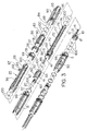
- hydraulic disconnect 1 as will now be described herein generally comprises from its uphole to its downhole ends 3 and 4 respectively, a tubular housing 2 comprising a tubular piston housing 15 threadedly connected to a tubular key retainer 25.
- the downhole end 26 of retainer 25 fits slidably into a bottom sub assembly consisting of a cylindrical cap 80 and a tubular bottom sub 90.
- End 3 of housing 15 is itself adapted for threaded connection to the downhole end 5 of a cylindrical seal sub 30 that forms part of a coiled tubing connector used to connect the terminal end of the tubing string (not shown) to the top of the bottom hole assembly of which the present disconnect is a part.
- a typical approach to a safety downhole disconnect in the event the tool string becomes stuck is to provide shear screws that couple the tubing string to the tool string. These screws are sheared off by pulling back on the tubing string with sufficient force to cause shearing. The shear strength of the tubing must therefore exceed that of the shear screws.
- This approach is described in the aforementioned '151 patent with particular reference to Figure 9 and shear screws 260 shown therein and the description thereof at column 9, line 27.
- the shear strength of coiled tubing is unpredictable however due to, inter alia , phenomena such as cycle fatigue induced in the tubing during spooling and unspooling operations from the storage reel and perhaps even more damagingly as the tubing passes back and forth over the guide arch used to direct the tubing into the tubing injector.
- open end 3 of housing 15 is fitted with a metallic cylindrical anchor plate 10 having a shoulder 11 that abuts against end 3 of housing 15 to limit the anchor plate's insertion.
- anchor plate 10 With seal sub 30 assembled to housing 15, anchor plate 10 is compressed between a shoulder 6 in the seal sub and end 3 of housing 15.
- the anchor plate includes two off-centre axially aligned apertures, the first of which, 12, is for a wire line or capillary tube 8 and the second of which, 17, is smooth-bored and larger in diameter for passage of a steel ball 20 the purpose of which will be described below.
- Capillary tube 8 is immovably connected to the anchor plate by buttress-threaded slips 13 and jamb nut 14.
- Sub 50 Downstream of anchor plate 10, bore 16 of housing 15 widens at shoulder 22 to concentrically and slidably receive therein a piston top sub 50.
- Sub 50 also includes two off-centre bores or apertures 52 and 53 formed therethrough to be in axial alignment with apertures 12 and 17 in anchor plate 10, respectively.
- Wire line 8 passes slidably through aperture 52 and is sealed against fluid leakage by packing 46 and jamb nut 47.
- the upstream end of aperture 53 supports a replaceable frusto-conical ball seat 60 held in place against shoulder 54 by a snap ring 57.
- ball seat 60 and the portion of aperture 53 downstream thereof define a funnel-mouthed flow channel 61 through piston top sub 50, this channel, at least through the ball seat, having an inner diameter smaller than that of ball 20 so that the ball closes the channel against fluid flow when required for disconnection as will be described in greater detail below.
- apertures 12 and 52 can be eliminated from anchor plate 10 and piston top sub 50, respectively, or they can simply be plugged. In fact, in such a situation, anchor plate 10 itself can be removed completely. It can remain in place of course but will serve no particular function. Aperture 52 in the piston top can be fitted with a one-way check or ball valve as an alternative to being plugged.
- Piston top sub 50 is threadedly connected to a piston bottom sub 70 including an upper body 71 that narrows in the downstream direction to form a mandrel 72.
- Mandrel 72 fits closely but slidably through the bore of key retainer 25 and it and the piston top sub are fixedly held in the position shown in Figure 1 relative to piston housing 15 and key retainer 25 by means of shear screws 65.
- Screws 65 pass through threaded apertures 66 in the downstream end 26 of the key retainer into an aligned annular groove 74 in the downstream end 77 of mandrel 72.
- four shear screws 65 spaced apart at 90 o intervals are used to make this connection.
- a tubular cap 80 and a threadedly connected bottom sub 90 are slidably installed over the downhole end 26 of key retainer 25 until contact is made between end 26 and an internal shoulder 91 on bottom sub 90.
- the bottom sub 90/cap 80 combination and key retainer 25 are locked together to prevent axial separation by means of chamfered pins or keys 68 that fit through apertures 67 in end 26 of key retainer 25 and engage an aligned annular notch or groove 82 defined by the adjoining surfaces 83 and 84 of cap 80 and bottom sub 90 respectively.
- key retainer 25 is moved upstream to expose apertures 67, and bottom sub 90 is removed if previously assembled to cap 80. The keys are then manually inserted into the apertures. Some grease applied to the keys will help hold them in place in apertures 67 as key retainer 25 is moved back into place to align shear screws 65 with annular groove 74. Once screws 65 have been fully driven into groove 74, sub 90 can be reinstalled to complete assembly.
- the downhole end 93 of bottom sub 90 includes drilling threads 95 for connection to the remainder of the tool string for make-up or disassembly. It's therefore desirable that the bottom sub be rotatable to facilitate its connection to the tool string. During drilling operations however, the bottom sub should be non-rotatably locked to the rest of the disconnect. This locking also serves to inhibit rotation of the tool assembly otherwise occurring due to the transmission of torque from the bit/rock interface.
- key retainer 25 is externally threaded at 23 for connection to a correspondingly internally threaded locking nut 35 which, by simple rotation, can be backed off in the direction of arrow B.
- Locking nut 35 abuts against a concentric slider 36 having radially inwardly extending splines 37 that mesh with cooperating radially outwardly extending splines 38 formed on the outer surface of key retainer 25.
- the splines 37 and 38 obviously prevent the slider from rotating relative to the key retainer.
- a plurality of spaced apart lugs 39 are formed at the downhole end of slider 36 to mesh with correspondingly-shaped lugs 81 provided on the upstream end of cap 80 ( Figure 2). With lugs 39 and 81 meshed together, cap 80 and bottom sub 90 are non-rotatably locked to key retainer 25. By backing off locking nut 35 in the direction of arrow B so that slider 36 can also be backed off in the same direction, lugs 39 and 81 separate so that cap 80/sub 90 are then free to rotate relative to the key retainer.
- disconnect 1 is activated by pumping steel ball 20 from the surface through the tubing string and aperture 17 in anchor plate 10 and then into seat 60 to close flow channel 61.
- piston top sub 50 transmits the pressure of the drilling fluid against screws 65 via mandrel 72. This pressure is sufficient to cause shearing of the screws which in turn allows mandrel 72 and the other piston assembly components attached thereto to move in the downhole direction.
- the downhole travel of mandrel 72 is limited by contact between shoulder 69 on piston bottom sub 70 and the uphole end 24 of key retainer 25 so that an annular groove 75 in the mandrel aligns itself with keys 68.
- keys 68 will then fall or dislodge into groove 75 which is sufficiently deep that the keys completely disengage notches 82.
- Key retainer 25 can then be pulled clear simply by normal withdrawal of the coiled tubing from the hole. This leaves behind the buttress-threaded fishing neck 86 on cap 80 for retrieval of the tool assembly using conventional recovery techniques.
- set screws 99 are used to prevent the inadvertent backing off of the threaded connections between the various housings, subs, retainers and locking nuts described above.
- O rings 100 are placed where required to prevent the escape of drilling fluid flowing through the disconnect into the well bore to prevent a loss of circulation at the bit.
Landscapes
- Engineering & Computer Science (AREA)
- Geology (AREA)
- Life Sciences & Earth Sciences (AREA)
- Mining & Mineral Resources (AREA)
- Environmental & Geological Engineering (AREA)
- Fluid Mechanics (AREA)
- Physics & Mathematics (AREA)
- General Life Sciences & Earth Sciences (AREA)
- Geochemistry & Mineralogy (AREA)
- Mechanical Engineering (AREA)
- Earth Drilling (AREA)
- Quick-Acting Or Multi-Walled Pipe Joints (AREA)
- Automatic Assembly (AREA)
Applications Claiming Priority (2)
| Application Number | Priority Date | Filing Date | Title |
|---|---|---|---|
| CA002122958A CA2122958C (fr) | 1994-05-05 | 1994-05-05 | Methode et dispositif hydraulique de decouplage |
| CA2122958 | 1994-05-05 |
Publications (2)
| Publication Number | Publication Date |
|---|---|
| EP0681086A2 true EP0681086A2 (fr) | 1995-11-08 |
| EP0681086A3 EP0681086A3 (fr) | 1997-06-18 |
Family
ID=4153545
Family Applications (1)
| Application Number | Title | Priority Date | Filing Date |
|---|---|---|---|
| EP95103782A Withdrawn EP0681086A3 (fr) | 1994-05-05 | 1995-03-15 | Dispositif de séparation hydraulique. |
Country Status (5)
| Country | Link |
|---|---|
| US (1) | US5419399A (fr) |
| EP (1) | EP0681086A3 (fr) |
| AU (1) | AU695604B2 (fr) |
| CA (1) | CA2122958C (fr) |
| NO (1) | NO951001L (fr) |
Families Citing this family (39)
| Publication number | Priority date | Publication date | Assignee | Title |
|---|---|---|---|---|
| US5695009A (en) * | 1995-10-31 | 1997-12-09 | Sonoma Corporation | Downhole oil well tool running and pulling with hydraulic release using deformable ball valving member |
| CA2163946C (fr) * | 1995-11-28 | 1997-10-14 | Integrated Production Services Ltd. | Systeme d'ancrage pour support de train de tubes |
| US5810084A (en) * | 1996-02-22 | 1998-09-22 | Halliburton Energy Services, Inc. | Gravel pack apparatus |
| US5718291A (en) * | 1996-03-07 | 1998-02-17 | Baker Hughes Incorporated | Downhole disconnect tool |
| WO1998014685A2 (fr) * | 1996-10-04 | 1998-04-09 | Camco International, Inc. | Outil de deverrouillage d'urgence perfectionne |
| US5857710A (en) * | 1996-11-04 | 1999-01-12 | Schlumberger Technology Corporation | Multi-cycle releasable connection |
| US5984029A (en) * | 1997-02-06 | 1999-11-16 | Baker Hughes Incorporated | High-load hydraulic disconnect |
| US6213202B1 (en) * | 1998-09-21 | 2001-04-10 | Camco International, Inc. | Separable connector for coil tubing deployed systems |
| US6367552B1 (en) * | 1999-11-30 | 2002-04-09 | Halliburton Energy Services, Inc. | Hydraulically metered travel joint |
| US6318470B1 (en) * | 2000-02-15 | 2001-11-20 | Halliburton Energy Services, Inc. | Recirculatable ball-drop release device for lateral oilwell drilling applications |
| US6408946B1 (en) | 2000-04-28 | 2002-06-25 | Baker Hughes Incorporated | Multi-use tubing disconnect |
| US6571879B1 (en) | 2000-11-08 | 2003-06-03 | Baker Hughes Incorporated | Surface-actuated release tool for submersible pump assemblies |
| GB0029097D0 (en) * | 2000-11-29 | 2001-01-10 | B D Kendle Engineering Ltd | Dimple disconnect |
| NO318013B1 (no) * | 2003-03-21 | 2005-01-17 | Bakke Oil Tools As | Anordning og fremgangsmåte for frakopling av et verktøy fra en rørstreng |
| US8079413B2 (en) | 2008-12-23 | 2011-12-20 | W. Lynn Frazier | Bottom set downhole plug |
| US8496052B2 (en) | 2008-12-23 | 2013-07-30 | Magnum Oil Tools International, Ltd. | Bottom set down hole tool |
| US9181772B2 (en) | 2009-04-21 | 2015-11-10 | W. Lynn Frazier | Decomposable impediments for downhole plugs |
| US9127527B2 (en) | 2009-04-21 | 2015-09-08 | W. Lynn Frazier | Decomposable impediments for downhole tools and methods for using same |
| US9109428B2 (en) | 2009-04-21 | 2015-08-18 | W. Lynn Frazier | Configurable bridge plugs and methods for using same |
| US9163477B2 (en) | 2009-04-21 | 2015-10-20 | W. Lynn Frazier | Configurable downhole tools and methods for using same |
| US9062522B2 (en) | 2009-04-21 | 2015-06-23 | W. Lynn Frazier | Configurable inserts for downhole plugs |
| US9562415B2 (en) | 2009-04-21 | 2017-02-07 | Magnum Oil Tools International, Ltd. | Configurable inserts for downhole plugs |
| US8418771B2 (en) | 2009-07-31 | 2013-04-16 | Baker Hughes Incorporated | Method and apparatus for releasing a coiled tubing internal conduit from a bottom hole assembly |
| US8464788B2 (en) | 2010-10-19 | 2013-06-18 | E. Brace Tool Inc. | Hydraulic disconnect |
| US8479827B2 (en) | 2011-01-31 | 2013-07-09 | Baker Hughes Incorporated | Disconnect devices for downhole strings |
| USD694280S1 (en) | 2011-07-29 | 2013-11-26 | W. Lynn Frazier | Configurable insert for a downhole plug |
| USD672794S1 (en) | 2011-07-29 | 2012-12-18 | Frazier W Lynn | Configurable bridge plug insert for a downhole tool |
| USD703713S1 (en) | 2011-07-29 | 2014-04-29 | W. Lynn Frazier | Configurable caged ball insert for a downhole tool |
| USD673183S1 (en) | 2011-07-29 | 2012-12-25 | Magnum Oil Tools International, Ltd. | Compact composite downhole plug |
| USD684612S1 (en) | 2011-07-29 | 2013-06-18 | W. Lynn Frazier | Configurable caged ball insert for a downhole tool |
| USD694281S1 (en) | 2011-07-29 | 2013-11-26 | W. Lynn Frazier | Lower set insert with a lower ball seat for a downhole plug |
| USD698370S1 (en) | 2011-07-29 | 2014-01-28 | W. Lynn Frazier | Lower set caged ball insert for a downhole plug |
| USD657807S1 (en) | 2011-07-29 | 2012-04-17 | Frazier W Lynn | Configurable insert for a downhole tool |
| USD673182S1 (en) | 2011-07-29 | 2012-12-25 | Magnum Oil Tools International, Ltd. | Long range composite downhole plug |
| CN102261227B (zh) * | 2011-08-16 | 2014-03-12 | 四川宏华石油设备有限公司 | 一种连续油管牵引装置 |
| US9771762B2 (en) | 2014-02-07 | 2017-09-26 | Klx Energy Services Llc | Downhole separation apparatus and method |
| US9267338B1 (en) * | 2015-03-31 | 2016-02-23 | Coiled Tubing Rental Tools, Inc. | In-well disconnect tool |
| US12312883B2 (en) | 2023-06-30 | 2025-05-27 | Toby Scott Baudoin | Safety separation apparatus and method |
| US12492606B1 (en) * | 2024-08-22 | 2025-12-09 | Baker Hughes Oilfield Operations Llc | Fiber optic monitoring in chemical injection and gas lift systems |
Family Cites Families (9)
| Publication number | Priority date | Publication date | Assignee | Title |
|---|---|---|---|---|
| US4601492A (en) * | 1982-10-20 | 1986-07-22 | Geo Vann, Inc. | Releasable coupling |
| US4760884A (en) * | 1986-09-16 | 1988-08-02 | Halliburton Company | Air chamber actuated dual tubing release assembly |
| US5086844A (en) * | 1989-10-10 | 1992-02-11 | Union Oil Company Of California | Hydraulic release oil tool |
| US5146984A (en) * | 1991-04-09 | 1992-09-15 | Otis Engineering Corporation | Emergency release device for connecting between tubular members in oil and gas wells |
| US5133412A (en) * | 1991-06-14 | 1992-07-28 | Baker Hughes Incorporated | Pull release device with hydraulic lock for electric line setting tool |
| US5215151A (en) * | 1991-09-26 | 1993-06-01 | Cudd Pressure Control, Inc. | Method and apparatus for drilling bore holes under pressure |
| US5219027A (en) * | 1991-12-17 | 1993-06-15 | Taylor William T | Hydraulic release tool |
| US5201814A (en) * | 1992-01-23 | 1993-04-13 | Conoco Inc. | Breakaway coupling device |
| US5417291A (en) * | 1993-05-14 | 1995-05-23 | Dowell, A Division Of Schlumberger Technology Corporation | Drilling connector |
-
1994
- 1994-05-05 CA CA002122958A patent/CA2122958C/fr not_active Expired - Fee Related
- 1994-06-28 US US08/267,779 patent/US5419399A/en not_active Expired - Fee Related
-
1995
- 1995-03-15 NO NO951001A patent/NO951001L/no unknown
- 1995-03-15 EP EP95103782A patent/EP0681086A3/fr not_active Withdrawn
- 1995-03-15 AU AU14834/95A patent/AU695604B2/en not_active Ceased
Also Published As
| Publication number | Publication date |
|---|---|
| EP0681086A3 (fr) | 1997-06-18 |
| NO951001D0 (no) | 1995-03-15 |
| CA2122958A1 (fr) | 1995-11-06 |
| US5419399A (en) | 1995-05-30 |
| CA2122958C (fr) | 1998-02-10 |
| NO951001L (no) | 1995-11-06 |
| AU695604B2 (en) | 1998-08-20 |
| AU1483495A (en) | 1995-11-16 |
Similar Documents
| Publication | Publication Date | Title |
|---|---|---|
| US5419399A (en) | Hydraulic disconnect | |
| AU751952B2 (en) | Bottom hole assembly with coiled tubing insert | |
| AU2002346541B2 (en) | Downhole assembly releasable connection | |
| CA2400132C (fr) | Dispositif de deblocage-abaissement a recirculation de bille pour applications de forage petrolier lateral | |
| US6568471B1 (en) | Liner hanger | |
| US5947198A (en) | Downhole tool | |
| US8297365B2 (en) | Drilling string back off sub apparatus and method for making and using same | |
| EP0624709A2 (fr) | Connexion pour train de tiges | |
| EP0681085B1 (fr) | Connecteur pour des tubes flexibles | |
| AU2017225543A1 (en) | Frac plug | |
| US5146984A (en) | Emergency release device for connecting between tubular members in oil and gas wells | |
| CA2273607A1 (fr) | Dispositif de debranchement hydraulique de serpentin de forage | |
| US20200224504A1 (en) | Downhole Release Mechanism |
Legal Events
| Date | Code | Title | Description |
|---|---|---|---|
| PUAI | Public reference made under article 153(3) epc to a published international application that has entered the european phase |
Free format text: ORIGINAL CODE: 0009012 |
|
| AK | Designated contracting states |
Kind code of ref document: A2 Designated state(s): AT DE GB NL SE |
|
| PUAL | Search report despatched |
Free format text: ORIGINAL CODE: 0009013 |
|
| AK | Designated contracting states |
Kind code of ref document: A3 Designated state(s): AT DE GB NL SE |
|
| 17P | Request for examination filed |
Effective date: 19971218 |
|
| 17Q | First examination report despatched |
Effective date: 19991220 |
|
| STAA | Information on the status of an ep patent application or granted ep patent |
Free format text: STATUS: THE APPLICATION IS DEEMED TO BE WITHDRAWN |
|
| 18D | Application deemed to be withdrawn |
Effective date: 20000503 |