EP0681185A1 - Mess- und Dichtungsanordnung für Wälzlager - Google Patents
Mess- und Dichtungsanordnung für Wälzlager Download PDFInfo
- Publication number
- EP0681185A1 EP0681185A1 EP95106497A EP95106497A EP0681185A1 EP 0681185 A1 EP0681185 A1 EP 0681185A1 EP 95106497 A EP95106497 A EP 95106497A EP 95106497 A EP95106497 A EP 95106497A EP 0681185 A1 EP0681185 A1 EP 0681185A1
- Authority
- EP
- European Patent Office
- Prior art keywords
- ring
- magnetised
- unit
- axial
- magnetised ring
- Prior art date
- Legal status (The legal status is an assumption and is not a legal conclusion. Google has not performed a legal analysis and makes no representation as to the accuracy of the status listed.)
- Granted
Links
- 238000007789 sealing Methods 0.000 title claims abstract description 19
- 238000005096 rolling process Methods 0.000 title claims abstract description 12
- 230000011664 signaling Effects 0.000 claims description 20
- 230000002093 peripheral effect Effects 0.000 claims description 9
- 230000004323 axial length Effects 0.000 claims 1
- 239000000463 material Substances 0.000 description 4
- 230000008878 coupling Effects 0.000 description 3
- 238000010168 coupling process Methods 0.000 description 3
- 238000005859 coupling reaction Methods 0.000 description 3
- 239000000356 contaminant Substances 0.000 description 2
- 239000004519 grease Substances 0.000 description 2
- 230000001050 lubricating effect Effects 0.000 description 2
- 238000004519 manufacturing process Methods 0.000 description 2
- 230000009471 action Effects 0.000 description 1
- 230000002547 anomalous effect Effects 0.000 description 1
- 230000002452 interceptive effect Effects 0.000 description 1
- 238000000034 method Methods 0.000 description 1
- 230000004048 modification Effects 0.000 description 1
- 238000012986 modification Methods 0.000 description 1
- 230000008569 process Effects 0.000 description 1
- 230000001681 protective effect Effects 0.000 description 1
- 230000009467 reduction Effects 0.000 description 1
Images
Classifications
-
- F—MECHANICAL ENGINEERING; LIGHTING; HEATING; WEAPONS; BLASTING
- F16—ENGINEERING ELEMENTS AND UNITS; GENERAL MEASURES FOR PRODUCING AND MAINTAINING EFFECTIVE FUNCTIONING OF MACHINES OR INSTALLATIONS; THERMAL INSULATION IN GENERAL
- F16C—SHAFTS; FLEXIBLE SHAFTS; ELEMENTS OR CRANKSHAFT MECHANISMS; ROTARY BODIES OTHER THAN GEARING ELEMENTS; BEARINGS
- F16C33/00—Parts of bearings; Special methods for making bearings or parts thereof
- F16C33/72—Sealings
- F16C33/76—Sealings of ball or roller bearings
- F16C33/78—Sealings of ball or roller bearings with a diaphragm, disc, or ring, with or without resilient members
- F16C33/7869—Sealings of ball or roller bearings with a diaphragm, disc, or ring, with or without resilient members mounted with a cylindrical portion to the inner surface of the outer race and having a radial portion extending inward
- F16C33/7879—Sealings of ball or roller bearings with a diaphragm, disc, or ring, with or without resilient members mounted with a cylindrical portion to the inner surface of the outer race and having a radial portion extending inward with a further sealing ring
-
- F—MECHANICAL ENGINEERING; LIGHTING; HEATING; WEAPONS; BLASTING
- F16—ENGINEERING ELEMENTS AND UNITS; GENERAL MEASURES FOR PRODUCING AND MAINTAINING EFFECTIVE FUNCTIONING OF MACHINES OR INSTALLATIONS; THERMAL INSULATION IN GENERAL
- F16C—SHAFTS; FLEXIBLE SHAFTS; ELEMENTS OR CRANKSHAFT MECHANISMS; ROTARY BODIES OTHER THAN GEARING ELEMENTS; BEARINGS
- F16C41/00—Other accessories, e.g. devices integrated in the bearing not relating to the bearing function as such
- F16C41/007—Encoders, e.g. parts with a plurality of alternating magnetic poles
-
- G—PHYSICS
- G01—MEASURING; TESTING
- G01P—MEASURING LINEAR OR ANGULAR SPEED, ACCELERATION, DECELERATION, OR SHOCK; INDICATING PRESENCE, ABSENCE, OR DIRECTION, OF MOVEMENT
- G01P3/00—Measuring linear or angular speed; Measuring differences of linear or angular speeds
- G01P3/42—Devices characterised by the use of electric or magnetic means
- G01P3/44—Devices characterised by the use of electric or magnetic means for measuring angular speed
- G01P3/443—Devices characterised by the use of electric or magnetic means for measuring angular speed mounted in bearings
-
- F—MECHANICAL ENGINEERING; LIGHTING; HEATING; WEAPONS; BLASTING
- F16—ENGINEERING ELEMENTS AND UNITS; GENERAL MEASURES FOR PRODUCING AND MAINTAINING EFFECTIVE FUNCTIONING OF MACHINES OR INSTALLATIONS; THERMAL INSULATION IN GENERAL
- F16C—SHAFTS; FLEXIBLE SHAFTS; ELEMENTS OR CRANKSHAFT MECHANISMS; ROTARY BODIES OTHER THAN GEARING ELEMENTS; BEARINGS
- F16C2326/00—Articles relating to transporting
- F16C2326/01—Parts of vehicles in general
- F16C2326/02—Wheel hubs or castors
Definitions
- the present invention relates to a sensor and sealing unit for a rolling bearing.
- the multi-functional unit according to the present invention is of the type comprising a sealed assembly for protecting the rolling bodies of the bearing from external contaminants and, at the same time, for holding the lubricating grease within the bearing, and a signalling member fixed to a rotatable element of the bearing and adapted to cooperate with a detector device outside the unit and fixable to a fixed element of the bearing to detect the speed of rotation of the movable element of the bearing and/or of any mechanical member fixed thereto such as, for example, a wheel of a vehicle.
- Units of the type specified above are known in which the signalling member is fixed to a shield of the sealing assembly by a specific locking support; more particularly, a unit is known from European Patent EP 0378939-B1 in which the signalling member, constituted by a magnetised ring, is located in axial abutment with a stop surface of the shield and has teeth on its cylindrical surface which fit into corresponding seats in the shield.
- This known unit has disadvantages linked on the one hand to the differential thermal expansion to which its components may be subject because of the different materials from which they are made, which expansion can cause interference between elements of the unit which rotate relative to each other in use; and, on the other hand, connected to the manufacturing tolerances of the toothed couplings which are necessarily tight and the reduction of magnetised material of the ring which these involve.
- the object of the present invention is to produce a sensor and sealing unit which is free from the problems described and, in particular, is simple and economical to construct and assemble.
- a sensor and sealing unit for a rolling bearing adapted to seal, in a fluid-tight manner, an annular space formed between respective relatively-movable rings of the bearing and housing respective rolling bodies of the bearing, the unit including a shield which can be fixed in a fluid-tight manner to a first ring of the bearing and having an elastomeric sealing member adapted to cooperate in a fluid-tight manner with a sealing surface fixed to a second ring of the bearing and a signalling member formed by a magnetised ring adapted to cooperate with a detector device which can be fixed to the second ring; characterised in that the magnetised ring is housed with radial interference in an annular blind seat of the shield from which the magnetised ring projects axially in a cantilevered fashion on the opposite side from said space; means being provided for the axial snap-locking of the magnetised ring in said annular blind seat.
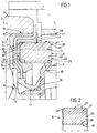
- a sensor and sealing unit for a rolling bearing 2 of a vehicle is indicated 1.
- the bearing 2 includes a rotatable outer ring 3; a fixed inner ring 4; and a plurality of rolling bodies 5 housed in a space 6 between the rings 3 and 4.
- the unit 1 includes a shield 7 located so as to close the space 6 and protect the rolling bodies 5 from external contaminants and to retain the lubricating grease within the bearing 2, and a signalling member 8 which cooperates with an external detector device (not illustrated) to detect the speed of rotation of a member supported for rotation by the bearing 2, for example a wheel hub (not illustrated) of a vehicle. More particularly, the unit 1 is fixed to the rotatable ring 3 of the bearing 2 while the detector device is carried in known manner, not illustrated for simplicity, by a closure element 9 which is constituted by a shield fixed to the fixed ring 4.
- the shield 7 includes a core 10 of rigid material defining a support structure of the unit 1 and an elastomeric element 14 in which the core 10 is partly embedded.
- the elastomeric element 14 has an upper portion 15 which is coupled in fluid-tight manner by a corrugated surface 16 to the ring 3 and a lower appendage 17 defining a V-shaped sealing lip which is located in fluid-tight sliding contact with a sealing surface 13 of the closure element 9 so as to form a seal with the ring 4.
- the elastomeric element 14 is shaped so as to present an annular blind seat 20 on the opposite side of the core 10 from the space 6, the blind seat being bounded by substantially cylindrical, mutually-facing walls 18 and 19 and by a base 12 defined by a surface of the core 10; the signalling member 8 is fixed within the seat 20 by friction against radial movement and by a snap-locking device 21 against axial movement.
- the signalling member 8 is constituted by a magnetised ring which is housed partly within the seat 20 so that a portion 22 thereof projects axially out of the unit 1 on the opposite side from the space 6. Moreover, the signalling member 8 is located in this seat 20 so that an axial clearance 23 remains between the base 12 of the shield 7 and the magnetised ring 8. More particularly, the clearance 23 has a predetermined axial dimension which is greater than the maximum axial thermal expansion envisaged for the magnetised ring 8.
- the locking device 21 comprises an annular projection 28 which projects radially inwardly of the seat 20 from the wall 18 of the elastomeric element 14 with which it is formed integrally.
- the magnetised ring 8 is, as already stated, clamped radially by interference within the annular seat 20 and thus, by virtue of the elastic yielding of the rubber walls 18 and 19, is subject to a compressive force which, through friction, keeps it fixed to the shield 7.
- This action of radial clamping by circumferential encircling is enhanced, in the embodiment illustrated, by the presence of an axial groove 29 formed in an inner peripheral wall 30 of the magnetised ring 8.
- this axial groove 29 is partly filled, in use, by an upset portion of the wall 19 of the elastomeric element 14 which forms a tooth thereon for locking it to signalling element 8 against relative rotation.
- only the radially outermost portion 31 of the magnetised ring 8 is in fact magnetised, this portion being bounded by the outer peripheral wall 25 in which the circumferential groove 27 is formed, and the ring has bevelled edges 33 connecting its end faces 26 to its inner peripheral wall 30 and to its outer peripheral wall 25.
- Figure 2 illustrates a variant of the signalling member 8 in which the end faces 26 are not flat but are concave inwardly of the magnetised ring 8 which thus does not run the risk of interfering accidentally with the detector device facing it in use.
- the signalling member 8 is locked to the shield 7 solely by the elastomeric element 14 which, in addition, insulates it from the heat which develops in the bearing 2 in use; this enables a locking system to be provided for the magnetised ring 8 which is both effective and economical.
- any differential thermal expansion in the present unit 1 does not cause axial interference between the shield 7 and the signalling member 8 since such expansion can be compensated for by the axial clearance 23.
- the signalling member 8 contacts solely the yielding walls 18 and 19 enables any radial differential expansion to be converted simply into increased interference which does none other than increase the clamping pressure on the components.
- the type of coupling provided between the components does not require tight manufacturing tolerances and hence eliminates the problems of toothed couplings used in known units.
- the axial locking achieved by the circumferential groove 27 in the magnetised ring 8 minimises the amount of magnetised material which must be removed and considerably simplifies the process by which the signalling member 8 is magnetised.
- the central position of the circumferential groove 27, the extension of the axial groove 29 along the entire axial dimension of the magnetised ring 8 and the recessed configuration of both end surfaces 26 of the magnetised ring 8 give the signalling member 8 a symmetry which simplifies the assembly of the unit 1 and eliminates any assembly problems linked to the positioning and orientation of the signalling member 8 which are normally particularly serious, especially considering the small dimensions of the components in question.
- the V-shape of the circumferential groove 27 enables the magnetised ring 8 to centre automatically, both axially and radially, on the shield 7 and minimises the clamping pressure on the annular projection 28. Moreover, any accidental contact between the signalling member 8 and the detector device cannot cause serious interference between the unit 1 and the detector device during rotation but, at most, causes anomalous wear of the edges 33.
Landscapes
- Engineering & Computer Science (AREA)
- General Engineering & Computer Science (AREA)
- Mechanical Engineering (AREA)
- Physics & Mathematics (AREA)
- General Physics & Mathematics (AREA)
- Sealing Of Bearings (AREA)
- Rolling Contact Bearings (AREA)
Applications Claiming Priority (2)
| Application Number | Priority Date | Filing Date | Title |
|---|---|---|---|
| ITTO940352A IT1273173B (it) | 1994-05-03 | 1994-05-03 | Gruppo sensore e di tenuta per un cuscinetto di rotolamento |
| ITTO940352 | 1994-05-03 |
Publications (2)
| Publication Number | Publication Date |
|---|---|
| EP0681185A1 true EP0681185A1 (de) | 1995-11-08 |
| EP0681185B1 EP0681185B1 (de) | 1999-01-27 |
Family
ID=11412500
Family Applications (1)
| Application Number | Title | Priority Date | Filing Date |
|---|---|---|---|
| EP95106497A Expired - Lifetime EP0681185B1 (de) | 1994-05-03 | 1995-04-28 | Mess- und Dichtungsanordnung für Wälzlager |
Country Status (3)
| Country | Link |
|---|---|
| EP (1) | EP0681185B1 (de) |
| DE (1) | DE69507530T2 (de) |
| IT (1) | IT1273173B (de) |
Cited By (11)
| Publication number | Priority date | Publication date | Assignee | Title |
|---|---|---|---|---|
| EP0709583A1 (de) * | 1994-10-31 | 1996-05-01 | Firma Carl Freudenberg | Dichtungsanordnung |
| EP0870940A3 (de) * | 1997-04-11 | 1999-01-13 | SKF INDUSTRIE S.p.A. | Dichtungsanordnung für zwei miteinander verbunene, relativ drehende Teile, insbesondere die zwei Ringe eines Rollenlagers |
| EP0937984A1 (de) * | 1998-02-24 | 1999-08-25 | SKF INDUSTRIE S.p.A. | Wälzlager mit Dichtmittel und Drehgeschwindigkeitsmesser |
| EP0875700A3 (de) * | 1997-04-29 | 1999-12-01 | SKF INDUSTRIE S.p.A. | Sensor-Dichtungseinheit für zwei relativ zueinander drehenden Teilen, insbesondre Rollenlager |
| US6109794A (en) * | 1997-07-17 | 2000-08-29 | Skf Industrie S.P.A. | Rolling contact bearing provided with a seal and an electrostatic current discharge device |
| US6323640B1 (en) | 1998-01-16 | 2001-11-27 | Skf Industrie S.P.A. | Rolling bearing unit with a rotating speed measuring device |
| US6491441B2 (en) | 1999-03-04 | 2002-12-10 | Skf Industrie S.P.A. | Tapered bearing unit |
| AU758216B2 (en) * | 1996-10-16 | 2003-03-20 | Sabo Industria E Comercio Ltda | Improvement in sealing |
| EP1160492A3 (de) * | 2000-05-31 | 2003-09-24 | Koyo Seiko Co., Ltd. | Dichtring, Dichtungsvorrichtung und Lagervorrichtung |
| FR2858418A1 (fr) * | 2003-07-31 | 2005-02-04 | Freudenberg Carl Kg | Generateur d'impulsions sur des dispositifs de saisie de la vitesse de rotation d'arbres, moyeux ou similaires. |
| DE102013223173A1 (de) * | 2013-11-14 | 2015-05-21 | Aktiebolaget Skf | Lageranordnung |
Citations (3)
| Publication number | Priority date | Publication date | Assignee | Title |
|---|---|---|---|---|
| JPS58171673A (ja) * | 1982-04-01 | 1983-10-08 | Nissan Motor Co Ltd | 内燃機関の回転検出装置 |
| FR2669728A1 (fr) * | 1990-11-28 | 1992-05-29 | Skf France | Dispositif a capteur actif pour la surveillance de l'etat de pneumatique d'une roue de vehicule et la mesure des caracteristiques de rotation de la roue. |
| DE9214980U1 (de) * | 1992-11-04 | 1992-12-24 | Skf Gmbh, 97421 Schweinfurt | Wälzlager mit Impulsring für ABS-Systeme |
-
1994
- 1994-05-03 IT ITTO940352A patent/IT1273173B/it active IP Right Grant
-
1995
- 1995-04-28 DE DE69507530T patent/DE69507530T2/de not_active Expired - Lifetime
- 1995-04-28 EP EP95106497A patent/EP0681185B1/de not_active Expired - Lifetime
Patent Citations (3)
| Publication number | Priority date | Publication date | Assignee | Title |
|---|---|---|---|---|
| JPS58171673A (ja) * | 1982-04-01 | 1983-10-08 | Nissan Motor Co Ltd | 内燃機関の回転検出装置 |
| FR2669728A1 (fr) * | 1990-11-28 | 1992-05-29 | Skf France | Dispositif a capteur actif pour la surveillance de l'etat de pneumatique d'une roue de vehicule et la mesure des caracteristiques de rotation de la roue. |
| DE9214980U1 (de) * | 1992-11-04 | 1992-12-24 | Skf Gmbh, 97421 Schweinfurt | Wälzlager mit Impulsring für ABS-Systeme |
Non-Patent Citations (1)
| Title |
|---|
| PATENT ABSTRACTS OF JAPAN vol. 8, no. 10 (P - 248)<1447> 18 January 1984 (1984-01-18) * |
Cited By (13)
| Publication number | Priority date | Publication date | Assignee | Title |
|---|---|---|---|---|
| EP0709583A1 (de) * | 1994-10-31 | 1996-05-01 | Firma Carl Freudenberg | Dichtungsanordnung |
| AU758216B2 (en) * | 1996-10-16 | 2003-03-20 | Sabo Industria E Comercio Ltda | Improvement in sealing |
| EP0870940A3 (de) * | 1997-04-11 | 1999-01-13 | SKF INDUSTRIE S.p.A. | Dichtungsanordnung für zwei miteinander verbunene, relativ drehende Teile, insbesondere die zwei Ringe eines Rollenlagers |
| EP0875700A3 (de) * | 1997-04-29 | 1999-12-01 | SKF INDUSTRIE S.p.A. | Sensor-Dichtungseinheit für zwei relativ zueinander drehenden Teilen, insbesondre Rollenlager |
| US6109794A (en) * | 1997-07-17 | 2000-08-29 | Skf Industrie S.P.A. | Rolling contact bearing provided with a seal and an electrostatic current discharge device |
| US6323640B1 (en) | 1998-01-16 | 2001-11-27 | Skf Industrie S.P.A. | Rolling bearing unit with a rotating speed measuring device |
| US6190051B1 (en) | 1998-02-24 | 2001-02-20 | Skf Industrie S.P.A. | Roller contact bearing with a sealing device and a device for rotation speed |
| EP0937984A1 (de) * | 1998-02-24 | 1999-08-25 | SKF INDUSTRIE S.p.A. | Wälzlager mit Dichtmittel und Drehgeschwindigkeitsmesser |
| US6491441B2 (en) | 1999-03-04 | 2002-12-10 | Skf Industrie S.P.A. | Tapered bearing unit |
| EP1160492A3 (de) * | 2000-05-31 | 2003-09-24 | Koyo Seiko Co., Ltd. | Dichtring, Dichtungsvorrichtung und Lagervorrichtung |
| FR2858418A1 (fr) * | 2003-07-31 | 2005-02-04 | Freudenberg Carl Kg | Generateur d'impulsions sur des dispositifs de saisie de la vitesse de rotation d'arbres, moyeux ou similaires. |
| DE102013223173A1 (de) * | 2013-11-14 | 2015-05-21 | Aktiebolaget Skf | Lageranordnung |
| DE102013223173B4 (de) * | 2013-11-14 | 2015-10-29 | Aktiebolaget Skf | Lageranordnung |
Also Published As
| Publication number | Publication date |
|---|---|
| IT1273173B (it) | 1997-07-07 |
| EP0681185B1 (de) | 1999-01-27 |
| ITTO940352A0 (it) | 1994-05-03 |
| DE69507530T2 (de) | 1999-08-26 |
| DE69507530D1 (de) | 1999-03-11 |
| ITTO940352A1 (it) | 1995-11-03 |
Similar Documents
| Publication | Publication Date | Title |
|---|---|---|
| US5522600A (en) | Annular lubricant seal assembly with spring member | |
| US3135518A (en) | Unitized radial shaft seals | |
| US3356376A (en) | Axle seal | |
| EP0227282B1 (de) | Vereinheitlichte Stirndichtungsvorrichtung | |
| CA1261894A (en) | Unitized seal | |
| US5046867A (en) | Bearing assembly speed sensor | |
| US4094512A (en) | Shaft seals | |
| US3813102A (en) | Locking and sealing ring | |
| US4428586A (en) | Combination wear sleeve and excluder lip adapted for easy installation | |
| EP0681185A1 (de) | Mess- und Dichtungsanordnung für Wälzlager | |
| KR0132299B1 (ko) | 유니버셜 조인트용 십자 부재 | |
| EP0385635B1 (de) | Dichtungen | |
| JP2000509791A (ja) | 軸受構造のための封止装置及び軸受装置の封止のための構造 | |
| US5127747A (en) | Bearing assembly speed sensor | |
| EP0099136B1 (de) | Eingepresste Drehmomentmitnahme für Schleifringdichtung | |
| US3594050A (en) | Means for mounting a bearing assembly in a housing | |
| CA2102472C (en) | Seal arrangement | |
| US5024450A (en) | Seal cartridge assembly | |
| JPH0320174A (ja) | シール装置 | |
| US5080500A (en) | Bearing assembly speed sensor mounted on carrier ring | |
| CA1118808A (en) | Seal for a rolling bearing | |
| JPH10319027A5 (de) | ||
| GB2313417A (en) | Cover for bearings | |
| HU192268B (en) | Antifriction bearing provided with packing | |
| US4260165A (en) | Shaft seal, intended for use at high temperatures |
Legal Events
| Date | Code | Title | Description |
|---|---|---|---|
| PUAI | Public reference made under article 153(3) epc to a published international application that has entered the european phase |
Free format text: ORIGINAL CODE: 0009012 |
|
| AK | Designated contracting states |
Kind code of ref document: A1 Designated state(s): DE FR GB SE |
|
| 17P | Request for examination filed |
Effective date: 19960404 |
|
| 17Q | First examination report despatched |
Effective date: 19970731 |
|
| GRAG | Despatch of communication of intention to grant |
Free format text: ORIGINAL CODE: EPIDOS AGRA |
|
| GRAG | Despatch of communication of intention to grant |
Free format text: ORIGINAL CODE: EPIDOS AGRA |
|
| GRAH | Despatch of communication of intention to grant a patent |
Free format text: ORIGINAL CODE: EPIDOS IGRA |
|
| GRAH | Despatch of communication of intention to grant a patent |
Free format text: ORIGINAL CODE: EPIDOS IGRA |
|
| GRAA | (expected) grant |
Free format text: ORIGINAL CODE: 0009210 |
|
| AK | Designated contracting states |
Kind code of ref document: B1 Designated state(s): DE FR GB SE |
|
| REF | Corresponds to: |
Ref document number: 69507530 Country of ref document: DE Date of ref document: 19990311 |
|
| ET | Fr: translation filed | ||
| PLBE | No opposition filed within time limit |
Free format text: ORIGINAL CODE: 0009261 |
|
| STAA | Information on the status of an ep patent application or granted ep patent |
Free format text: STATUS: NO OPPOSITION FILED WITHIN TIME LIMIT |
|
| 26N | No opposition filed | ||
| REG | Reference to a national code |
Ref country code: GB Ref legal event code: IF02 |
|
| PGFP | Annual fee paid to national office [announced via postgrant information from national office to epo] |
Ref country code: SE Payment date: 20040421 Year of fee payment: 10 Ref country code: GB Payment date: 20040421 Year of fee payment: 10 |
|
| PG25 | Lapsed in a contracting state [announced via postgrant information from national office to epo] |
Ref country code: GB Free format text: LAPSE BECAUSE OF NON-PAYMENT OF DUE FEES Effective date: 20050428 |
|
| PG25 | Lapsed in a contracting state [announced via postgrant information from national office to epo] |
Ref country code: SE Free format text: LAPSE BECAUSE OF NON-PAYMENT OF DUE FEES Effective date: 20050429 |
|
| EUG | Se: european patent has lapsed | ||
| GBPC | Gb: european patent ceased through non-payment of renewal fee |
Effective date: 20050428 |
|
| PGFP | Annual fee paid to national office [announced via postgrant information from national office to epo] |
Ref country code: DE Payment date: 20140627 Year of fee payment: 20 Ref country code: FR Payment date: 20140428 Year of fee payment: 20 |
|
| REG | Reference to a national code |
Ref country code: DE Ref legal event code: R071 Ref document number: 69507530 Country of ref document: DE |