EP0681244A2 - Système d'ordinateur portable pour résoudre les conflits entre l'ordinateur portable et une base d'extension - Google Patents
Système d'ordinateur portable pour résoudre les conflits entre l'ordinateur portable et une base d'extension Download PDFInfo
- Publication number
- EP0681244A2 EP0681244A2 EP95302966A EP95302966A EP0681244A2 EP 0681244 A2 EP0681244 A2 EP 0681244A2 EP 95302966 A EP95302966 A EP 95302966A EP 95302966 A EP95302966 A EP 95302966A EP 0681244 A2 EP0681244 A2 EP 0681244A2
- Authority
- EP
- European Patent Office
- Prior art keywords
- notebook computer
- computer system
- expansion
- expansion base
- docking
- Prior art date
- Legal status (The legal status is an assumption and is not a legal conclusion. Google has not performed a legal analysis and makes no representation as to the accuracy of the status listed.)
- Withdrawn
Links
Images


Classifications
-
- G—PHYSICS
- G06—COMPUTING OR CALCULATING; COUNTING
- G06F—ELECTRIC DIGITAL DATA PROCESSING
- G06F1/00—Details not covered by groups G06F3/00 - G06F13/00 and G06F21/00
- G06F1/16—Constructional details or arrangements
- G06F1/1613—Constructional details or arrangements for portable computers
- G06F1/1632—External expansion units, e.g. docking stations
-
- G—PHYSICS
- G06—COMPUTING OR CALCULATING; COUNTING
- G06F—ELECTRIC DIGITAL DATA PROCESSING
- G06F15/00—Digital computers in general; Data processing equipment in general
- G06F15/16—Combinations of two or more digital computers each having at least an arithmetic unit, a program unit and a register, e.g. for a simultaneous processing of several programs
- G06F15/177—Initialisation or configuration control
Definitions
- a depressed area 42 is located in the floor 30 into which a computer control plate 32 sits such that the top surface of the control plate 32 is substantially flushed with the floor 30.
- Two electrical sense pads 21 and 22 corresponding to the electrical sense pads 17 and 18 on the notebook computer 10 are located on the control plate 32.
- Two grab hooks 26 are rotatably connected to the control plate 32 by hinges 44. The control plate 32 slides in the direction of arrow B into the opening 36.
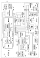
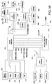
- FIG. 3A a block diagram of the expansion base unit 20 is shown, where Figure 3A shows the motherboard and Figure 3B shows the backplane.
- the connector 162 in the notebook computer 10 connects to a docking connector 200 when the notebook computer 10 is docked to the expansion base unit 20.
- the docking connector 200 provides signals to a parallel port connector 202, a serial port connector 204, a mouse connector 206, a keyboard connector 208 and a video connector 210.
- Various power control signals, battery signals, ISA bus signals, hard disk drive signals and floppy disk drive signals are connected between the docking connector 200 and a backplane edge connector 212.
- a microcontroller 214 is also connected to the power control signals.
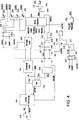
- the microcontroller 214 provides an output signal SMIREQ to the gate of an N-channel MOSFET 326.
- a resistor 324 is connected between the gate of the transistor 324 and ground.
- the source of the transistor 326 is connected to ground and its drain is connected to the signal SENSE.
- a resistor 328 is connected between the signal SENSE and ground and a resistor 327 is connected between the signal SENSE and the supply voltage +5V.
- the resistors 327 and 328 ensure that the SENSE input to the microcontroller 214 is at a voltage level between 0.75V and 1.75V when the notebook computer 10 is not present.
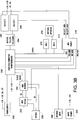
- the ISA data bus signals SD [4:0] are provided to the D inputs of a register 332 in the AEN enable logic 276. On the falling edge of a signal AENW*, which is asserted low when the address of the register 332 and the ISA write command signal IOWC* are provided, the state of the data bus SD [4:0] is loaded into the register 332.
- the outputs of the register 332 are provided to the enable inputs of tristate buffers 334, 336, 338 and 340 and to the AEN signal SAENSCSI.
- the inputs of the tristate buffers 334-340 are all connected to the ISA enable signal AEN.
- the microcontroller 214 ignores any eject requests asserted on the signal EJECTRQ.
- the signal KEYLOCK* is provided by the keylock 50 ( Figure 1). If asserted low, the signal KEYLOCK* prevents docking or ejection of the notebook computer 10.
- the signal PCMCIASN when asserted low, indicates that oversized PCMCIA cards or PCMCIA cards having attached cables are inserted into the PCMCIA slots 164 and 166 of the notebook computer 10. The signal PCMCIASN prevents ejection of the notebook computer 10 when the PCMCIA slots 164 and 166 are thus occupied to avoid damaging the oversized PCMCIA cards or the cables and PCMCIA cards.
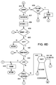
- step 400 determines whether the smart docking capability is enabled. If it is determined in step 400 that the smart docking capability is enabled, control proceeds to step 406.
- step 406 the microcontroller 214 determines the state of the notebook computer 10 by checking the voltage of the signal SENSE. If the state NEVER is indicated, then control proceeds to step 407, where an audible alarm is sounded on the speaker 222 ( Figure 3A) to let the user know that the notebook computer 10 cannot be docked or undocked from the expansion base unit 20. From step 407, control returns to the main routine on the microcontroller 214. If it is determined in step 406 that the notebook computer 10 is in the state OK, control proceeds to step 410 in Figure 6B.
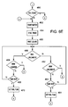
- step 552 the operating system is notified of the type of failure that has occurred. If it is determined that the battery is present in step 552, control proceeds to step 556.
- step 556 the SMI handler posts a Plug and Play message ABOUT_TO_CHANGE_CONFIG, which informs the operating system that a configuration change is about to be made to the notebook computer 10, including the initiation of a docking or undocking sequence.
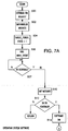
- step 700 If it is determined in step 700 that the motor 218 has just run, control proceeds from step 700 to step 710, where the signal SENSE is set to the state CONSIDER. This allows the microcontroller 214 in the expansion base unit 20 to respond to future docking or undocking requests. From step 710, control proceeds to step 712, where the dock ID information is reloaded. Control proceeds next to step 714, where it is determined if the notebook computer 10 was previously docked or undocked. Whether the notebook computer 10 is docked or undocked is determined by the signal EBOX*. If EBOX* is asserted low, that indicates the expansion base unit 20 is attached. Otherwise, the notebook computer 10 is not docked.
- step 714 if it is determined that the notebook computer 10 was previously docked, control proceeds to step 737, where it is determined if the notebook computer 10 is currently docked or undocked. Since the notebook computer 10 was previously docked and the motor has just run, it is anticipated that the notebook computer 10 should be ejected. If it is determined in step 737 that the notebook computer 10 is still docked to the expansion base unit 20, control proceeds to step 718, where the SMI handler posts the message CONFIG_CHANGE_FAILED with a hardware error message.
Landscapes
- Engineering & Computer Science (AREA)
- Theoretical Computer Science (AREA)
- Computer Hardware Design (AREA)
- Physics & Mathematics (AREA)
- General Engineering & Computer Science (AREA)
- General Physics & Mathematics (AREA)
- Software Systems (AREA)
- Human Computer Interaction (AREA)
- Power Sources (AREA)
Applications Claiming Priority (4)
| Application Number | Priority Date | Filing Date | Title |
|---|---|---|---|
| US23827194A | 1994-05-04 | 1994-05-04 | |
| US237778 | 1994-05-04 | ||
| US08/237,778 US5488572A (en) | 1994-05-04 | 1994-05-04 | Portable computer system for docking to an expansion base unit |
| US238271 | 1994-05-04 |
Publications (2)
| Publication Number | Publication Date |
|---|---|
| EP0681244A2 true EP0681244A2 (fr) | 1995-11-08 |
| EP0681244A3 EP0681244A3 (fr) | 1996-11-27 |
Family
ID=26931031
Family Applications (1)
| Application Number | Title | Priority Date | Filing Date |
|---|---|---|---|
| EP95302966A Withdrawn EP0681244A3 (fr) | 1994-05-04 | 1995-05-01 | Système d'ordinateur portable pour résoudre les conflits entre l'ordinateur portable et une base d'extension. |
Country Status (2)
| Country | Link |
|---|---|
| EP (1) | EP0681244A3 (fr) |
| CA (1) | CA2148181A1 (fr) |
Cited By (1)
| Publication number | Priority date | Publication date | Assignee | Title |
|---|---|---|---|---|
| US6745330B1 (en) | 1999-06-22 | 2004-06-01 | Hewlett-Packard Company, L.P. | Computer system having peripheral device look |
Family Cites Families (4)
| Publication number | Priority date | Publication date | Assignee | Title |
|---|---|---|---|---|
| EP0429780B1 (fr) * | 1989-11-29 | 1997-11-12 | Kabushiki Kaisha Toshiba | Système ordinateur pouvant connecter une unité d'expansion |
| JP3245861B2 (ja) * | 1990-11-19 | 2002-01-15 | セイコーエプソン株式会社 | ドッキングシステム |
| US5265238A (en) * | 1991-01-25 | 1993-11-23 | International Business Machines Corporation | Automatic device configuration for dockable portable computers |
| US5323291A (en) * | 1992-10-15 | 1994-06-21 | Apple Computer, Inc. | Portable computer and docking station having an electromechanical docking/undocking mechanism and a plurality of cooperatively interacting failsafe mechanisms |
-
1995
- 1995-04-28 CA CA 2148181 patent/CA2148181A1/fr not_active Abandoned
- 1995-05-01 EP EP95302966A patent/EP0681244A3/fr not_active Withdrawn
Cited By (1)
| Publication number | Priority date | Publication date | Assignee | Title |
|---|---|---|---|---|
| US6745330B1 (en) | 1999-06-22 | 2004-06-01 | Hewlett-Packard Company, L.P. | Computer system having peripheral device look |
Also Published As
| Publication number | Publication date |
|---|---|
| EP0681244A3 (fr) | 1996-11-27 |
| CA2148181A1 (fr) | 1995-11-05 |
Similar Documents
| Publication | Publication Date | Title |
|---|---|---|
| US5488572A (en) | Portable computer system for docking to an expansion base unit | |
| US5596728A (en) | Method and apparatus for resolving resource conflicts after a portable computer has docked to an expansion base unit | |
| EP0820022B1 (fr) | Système d'ordinateur incorporant des possibilités d'insertion et d'extraction en ligne ne nécessitant pas de mode de veille ou suspendu | |
| US5798951A (en) | Method and apparatus for automatic un-preconditioned insertion/removal capability between a notebook computer and a docking station | |
| US6141711A (en) | Method and apparatus to enable insertion/ejection of a device in a computer system while maintaining operation of the computer system and application software | |
| US6460106B1 (en) | Bus bridge for hot docking in a portable computer system | |
| US6125449A (en) | Controlling power states of a computer | |
| US5721935A (en) | Apparatus and method for entering low power mode in a computer system | |
| EP0780755B1 (fr) | Circuit destiné à fixer des signaux du bus d'un système d'ordinateur à des valeurs prédéterminées en mode faible consommation | |
| EP0364222B2 (fr) | Dispositif pour réduire la consommation d'énergie dans un ordinateur | |
| US5675364A (en) | Display wakeup control | |
| US6055643A (en) | System management method and apparatus for supporting non-dedicated event detection | |
| US5875307A (en) | Method and apparatus to enable docking/undocking of a powered-on bus to a docking station | |
| US5948074A (en) | Expansion unit having a security mechanism for inhibiting attachment and disconnection of the expansion unit to and from a portable computer | |
| US6070215A (en) | Computer system with improved transition to low power operation | |
| US20030159076A1 (en) | Keyboard controller providing power management for a portable computer system | |
| US6088620A (en) | Computer system in which a high-order application program recognizes a power-on factor or a state of an expansion unit | |
| US5796992A (en) | Circuit for switching between synchronous and asynchronous memory refresh cycles in low power mode | |
| JPH11288334A (ja) | コンピュータ・システムのパワーダウン方法及び装置 | |
| US20030041273A1 (en) | Method of synchronizing operation frequencies of CPU and system RAM in power management process | |
| US5634132A (en) | Operating system independent support for mixed voltage devices | |
| US6993670B2 (en) | Method of configuring a computer system capable of being woken up on LAN | |
| US6990546B2 (en) | Hot docking drive wedge and port replicator | |
| US5721836A (en) | Method and apparatus for sensing and changing the state of a computer before connecting the computer to or disconnecting the computer from an expansion unit | |
| EP0681244A2 (fr) | Système d'ordinateur portable pour résoudre les conflits entre l'ordinateur portable et une base d'extension |
Legal Events
| Date | Code | Title | Description |
|---|---|---|---|
| PUAI | Public reference made under article 153(3) epc to a published international application that has entered the european phase |
Free format text: ORIGINAL CODE: 0009012 |
|
| AK | Designated contracting states |
Kind code of ref document: A2 Designated state(s): AT BE CH DE DK ES FR GB IE IT LI NL SE |
|
| PUAL | Search report despatched |
Free format text: ORIGINAL CODE: 0009013 |
|
| AK | Designated contracting states |
Kind code of ref document: A3 Designated state(s): AT BE CH DE DK ES FR GB IE IT LI NL SE |
|
| 17P | Request for examination filed |
Effective date: 19970516 |
|
| 17Q | First examination report despatched |
Effective date: 19991109 |
|
| STAA | Information on the status of an ep patent application or granted ep patent |
Free format text: STATUS: THE APPLICATION IS DEEMED TO BE WITHDRAWN |
|
| 18D | Application deemed to be withdrawn |
Effective date: 20000520 |