EP0681341A2 - Schneidklemmkontakt - Google Patents
Schneidklemmkontakt Download PDFInfo
- Publication number
- EP0681341A2 EP0681341A2 EP95200850A EP95200850A EP0681341A2 EP 0681341 A2 EP0681341 A2 EP 0681341A2 EP 95200850 A EP95200850 A EP 95200850A EP 95200850 A EP95200850 A EP 95200850A EP 0681341 A2 EP0681341 A2 EP 0681341A2
- Authority
- EP
- European Patent Office
- Prior art keywords
- terminal
- conductor
- cable
- slit
- insulation
- Prior art date
- Legal status (The legal status is an assumption and is not a legal conclusion. Google has not performed a legal analysis and makes no representation as to the accuracy of the status listed.)
- Withdrawn
Links
Images


Classifications
-
- H—ELECTRICITY
- H01—ELECTRIC ELEMENTS
- H01R—ELECTRICALLY-CONDUCTIVE CONNECTIONS; STRUCTURAL ASSOCIATIONS OF A PLURALITY OF MUTUALLY-INSULATED ELECTRICAL CONNECTING ELEMENTS; COUPLING DEVICES; CURRENT COLLECTORS
- H01R4/00—Electrically-conductive connections between two or more conductive members in direct contact, i.e. touching one another; Means for effecting or maintaining such contact; Electrically-conductive connections having two or more spaced connecting locations for conductors and using contact members penetrating insulation
- H01R4/24—Connections using contact members penetrating or cutting insulation or cable strands
- H01R4/2495—Insulation penetration combined with permanent deformation of the contact member, e.g. crimping
-
- H—ELECTRICITY
- H01—ELECTRIC ELEMENTS
- H01R—ELECTRICALLY-CONDUCTIVE CONNECTIONS; STRUCTURAL ASSOCIATIONS OF A PLURALITY OF MUTUALLY-INSULATED ELECTRICAL CONNECTING ELEMENTS; COUPLING DEVICES; CURRENT COLLECTORS
- H01R43/00—Apparatus or processes specially adapted for manufacturing, assembling, maintaining, or repairing of line connectors or current collectors or for joining electric conductors
- H01R43/01—Apparatus or processes specially adapted for manufacturing, assembling, maintaining, or repairing of line connectors or current collectors or for joining electric conductors for connecting unstripped conductors to contact members having insulation cutting edges
Definitions
- This invention relates to the termination of electrical cables and a method of making a terminal and cable assembly.
- Electrical cables are typically comprised of a center electrical conductor that is surrounded by insulation.
- Conventional crimp-on type electrical terminals have typically been used to provide a connection to the cable.
- Terminals of this type generally have a first crimp barrel portion which contacts the center electrical conductor and a second crimp barrel portion that attaches around the insulation of a cable. With this type of terminal, the end of the cable must be stripped of its insulation to bare a segment of the electrical conductor before the terminal can be attached.
- electrical cables may be comprised of an additional jacketing material which will be stripped and discarded along with the insulation in the conventional stripping operation, thereby adding additional expense.
- terminals Because of the processing and material waste costs associated with stripping the ends of a cable in preparation for termination, terminals have been developed that include a crimp barrel portion that attaches around the insulation of a cable and an insulation piercing portion to provide contact with the electrical conductor without stripping the end of the cable. With this type of terminal, material does not have to be stripped from the cable and discarded.
- Insulation piercing terminals have found widespread use. However, their use in some applications including the termination of automotive ignition cables has been limited. The reason is that particularly in ignition cable applications, insulation piercing terminals have proven to have inherent reliability problems.
- a conventional insulation piercing terminal uses sharp edges to cut through the jacket and insulation layers of an electrical cable. The sharp edges make electrical contact with the conductive core of the cable. When the cable assembly is put into use, the sharp edges can lead to high E-field stresses causing burn damage to the conductor.
- sharp terminal edges may cut the conductive core which is often comprised of soft non-metallic material. Core cutting or disfigurement can cause arc discharges to occur, which can also lead to conductor burn damage. In addition, inadvertent cutting of the conductive core lowers terminal pull-off forces.
- ignition cables are generally terminated according to a conventional stripping and crimp-barrel type terminal assembly. Therefore, typical termination of an ignition cable involves the process of removing and discarding insulation from the cable.
- This invention includes a novel insulation displacement terminal that does not require stripping insulation from a cable prior to termination and does not include the sharp edges associated with insulation displacement type termination typically required to pierce through the insulation of a cable.
- a slit is first prepared in the insulating material of a conductor near its end.
- the insulation displacement terminal is then crimped into the slit and a smooth surface of the terminal contacts the electrically conductive core without damaging or disfiguring the core.
- This type of assembly results in a more reliable method of cable termination.
- the contact that is established between the terminal and the conductive core of the cable may be more closely controlled and monitored.
- An insulation displacement terminal and method of termination in accordance with the present invention is characterised by forming a slit in the insulation of the conductor, placing the crimp barrel portion of a terminal about the conductor at the slit, and crimping insulation displacement tabs of the crimp barrel portion into the slit such that blunt loading edges contact the conductor.
- Figure 1A is a perspective view of a length of cable.
- Figure 1B is a perspective view of a length of cable with a slit end.
- Figure 1C is a perspective view of a terminal and cable assembly according to an embodiment of the present invention.
- Figure 1D is a sectional view taken generally along the plane indicated by lines 1D-1D in Figure 1C.
- Figure 2A is a perspective view of a length of cable with a slit end and an annular band disposed thereon.
- Figure 2B is a perspective view of the length of cable in Figure 2A with the annular band crimped into the slit.
- Figure 2C is a perspective view of the length of cable in Figure 2B with a terminal assembled thereon according to an embodiment of the present invention.
- Figure 2D is a sectional view taken generally along the plane indicated by lines 2D-2D in Figure 2C.
- Figure 3A is a perspective view of a length of cable with a slit end.
- Figure 3B is a cable and terminal assembly according to an embodiment of the present invention.
- Figure 4A is a perspective view of a length of cable with a slit end and having a terminal placed thereon.
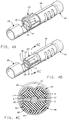
- Figure 4B is a cable and terminal assembly according to an embodiment of the present invention.
- Figure 4C is a sectional view taken generally along the plane indicated by lines 4C-4C in Figure 4B.
- Figure 5 is a cross sectional view of an embodiment of the present invention.
- Figure 1A shows the prepared end 11 of an ignition cable 10 which has been blunt cut in a conventional manner.
- the cable 10 is comprised of an electrically conductive core 12 having selected resistivity properties to properly perform in an automobile's ignition system (not illustrated).
- the core 12 may be comprised of a metallic wire wound construction which is noncompressible.
- the core 12 may also be comprised of strands, or a strand, of compressible non-metallic material such as high temperature nylons, polyamides, silicones and other high tensile strength materials which are coated, impregnated or otherwise suitably treated to make them electrically conductive.
- termination methods according to this invention are designed to be operable with both compressible and noncompressible cores, however, the embodiments of Figures 1A-1D, 2A-2D and 3A-3B, are more suited to use with noncompressible, wire wound core cables.
- a layer of EPDM or SBR synthetic rubber insulation 14 or a like material Surrounding the conductive core 12, of cable 10, is a layer of EPDM or SBR synthetic rubber insulation 14 or a like material. Surrounding the insulating layer 14 is a jacket layer 16 of Hypalon, Cosil, silicone or similar jacketing materials. The insulating layer 14 and jacketing layer 16 materials are relatively expensive and therefore preferably not discarded.
- the cable 10 is cut to the preferred length for its intended use through a blunt cutting process. This preparation leaves a prepared end of this cable segment and a leading end of the next segment ready for the termination process.
- Figure 1B illustrates a longitudinal axial slit 15 that has been prepared in the insulating layer 14 and jacketing layer 16 material of the cable 10. Notable, is the fact that the slit 15 does not extend axially completely to the conductive core 12 of the cable 10. This insures that the conductive core 10 is not marred or deformed in any manner during the slitting process. Due to preparation of the slit 15 in the insulating layer 14 and jacketing layer 16, the terminal does not require a sharp edge to displace the insulation 14 and jacketing 16 to contact the conductive core 12.
- Figure 1C illustrates the application of a terminal 18 to the prepared cable 10.
- the terminal 18 may be of a conventional ignition type or a modified version, but in either case has blunt edges 4 and 5 on the tabs, referred to as crimp wings 17 and 19. Edges 4 and 5 are slightly bent to present smooth surfaces adjacent the edges to contact the core thereby preventing arcing when the cable is put into use.
- the terminal 18 is crimped into the longitudinal axial slit 15 that has been prepared in the cable 10.
- the crimping operation causes the blunt edges 4 and 5 of the crimp wings 17 and 19 to displace the remaining insulation disposed around conductive core 12. Smooth surfaces on crimp wings 17 and 19, adjacent to blunt edges 4 and 5, make electrical contact with the conductive core 12 through the slit 15 area. In this assembly process, both the electrical and the mechanical crimps are performed simultaneously.
- Figure 1D illustrates in cross section the assembly illustrated in Figure 1C.
- the crimp wings 17 and 19 of the crimped terminal 18 extend axially through the jacketing layer 16 and insulating layer 14 of the cable 10 and the blunt edges 4 and 5 are slightly bent, providing smooth surfaces for contacting the conductive core 12.
- the blunt edges 4 and 5 can contact the core directly.
- the electrical contact that is established between the terminal 18 and the conductive core 12 avoids the creation of high E-field stresses that were likely to occur with previous insulation piercing terminal construction.
- Figures 2A-2D illustrate an alternative embodiment of the present invention.
- Figure 2A illustrates the end of an ignition cable 20 that has been prepared by being blunt cut at 21 and slit at 25.
- the prepared slit 25 extends longitudinally and axially through the jacket layer 26 but only substantially through the insulating layer 24 stopping short of the conductive core 22.
- annular metal band 8 that has been placed over the prepared end of the cable 20 and is disposed around the slit 25.
- annular metal band 8 has been F-crimped into the prepared slit 25. As the annular metal band 8 is being crimped, it displaces the remaining insulation that exists at the bottom of slit 25 about the conductive core 22, to establish electrical contact between the band 8 and the core 22.
- a terminal 28 is disposed over the crimped annular metal band 8.
- Crimp barrel 29 is crimped onto the end of the cable 20 to mechanically attach the terminal 28 to the cable 20 and to establish electrical continuity between the core 22, annular metal band 8 and terminal 28.
- Figure 2D illustrates in cross section the assembly of Figure 2C.
- the annular metal band 8 extends through the jacketing layer 26 and insulating layer 24 providing a smooth surface establishing electrical contact with the conductive core 22.
- the crimp barrel 29 of terminal 28 is crimped around the outside diameter of the annular metal band 8 and establishes electrical contact therebetween.
- Figures 3A and 3B illustrate an alternative embodiment of the present invention.
- the end of a cable 30 has been prepared with a longitudinal slit 35 extending axially through the jacketing layer 36 and substantially through the insulating layer 34 stopping short of the conductive core 32.
- a lateral slit 37 is similarly formed perpendicular to and contiguous with, the longitudinal slit 35 at its end, opposite the end 31 of the cable 30.
- Figure 3B illustrates the prepared cable 30 from Figure 3A with a terminal 38 added.
- the terminal 38 has a two-part crimp barrel area.
- the first portion, crimp barrel 33, of the crimp barrel area has been crimped into the longitudinal slit 35.
- the ends of the crimp wings 104 and 105 are slightly bent to provide a smooth surface establishing an electrical contact with the conductive core 32.
- the second portion, crimp barrel 39, of the crimp barrel area is secured about the insulating jacket layer 36 adjacent to the lateral slit 37.
- the first portion 33 of the crimp barrel area is formed such that during crimping the tabs are directed into the longitudinal slit 35, displacing the remaining cable insulation that is disposed about the conductive core 32. Crimping establishes electrical contact between smooth surfaces adjacent to or at the edges 104 and 105 of the crimp barrel wings and the conductive core 32.
- the lateral slit 37 that has been prepared substantially through the insulating layer 34 and through the jacketing layer 36 inhibits the propagation of the longitudinal slit 35 that could otherwise be induced along the cable 30 by the crimping process.
- the second portion of the crimp barrel area, crimp barrel 39 provides the mechanical crimping function and utilizes a round crimped configuration to optimize mechanical retention characteristics of the terminal 38 on the cable 30.
- FIGS 4A-4C illustrate another embodiment of the present invention.
- This embodiment includes a split crimp barrel area with the first portion of the crimp barrel area, crimp barrel 43, providing electrical contact with the conductive core.
- Crimp barrel 43 is comprised of a gull-wing type construction for a dual F-crimped assembly.
- the end of the ignition cable 40 has been prepared with two longitudinal slits 45 and 47 through the jacketing layer 46 and substantially through the insulating layer 44 stopping short of the conductive core 42.
- the longitudinal slits 45 and 47 are disposed diametrically on opposite sides of the conductive core 42.
- a terminal 48 is positioned over the end of the prepared cable 40 .
- Figure 4B illustrates the terminal 48 crimped onto the cable 40.
- the crimp wings on the crimp barrel 43 of the terminal 48 establish electrical contact with the core 42 and have two F-crimped parts 2 and 3 disposed through the insulating layer 44 and jacketing layer 46, establishing electrical contact with the conductive core 42.
- As the wing parts 2 and 3 are F-crimped onto the cable 40 they displace the remaining insulating material that is disposed about the conductive core 42 at the bottom of the longitudinal slits 45 and 47.
- the second portion of the crimp barrel area, crimp barrel 49 is mechanically crimped around the insulating and jacketing material.
- Figure 4C illustrates in cross section the assembly of Figure 4B.
- the dual F-crimp construction assures accuracy of the electrical contact that is established between the crimp wings and the conductive core 42.
- Smooth surfaces 114 and 115 of the terminal 48 provide electrical contact with the conductive core 42, avoiding the problems associated with disfigurement of the core when piercing type contact is used.
- Figure 5 shows in cross section an assembly similar to that of Figure 4C.
- the additional component included in Figure 5 is the C-shaped interlock 53 provided at the ends of the crimp wings 51 and 52.
- the advantage of providing C-interlock 53 is that compression set is minimized. Stated otherwise, providing the C-interlock 53 in the ends of the crimp wings 51 and 52 insures that if relaxation of the metal terminal 58 occurs from exposure to high temperatures or other factors, the electrical contact between the terminal 58 and the conductive core 55 is not degraded by movement of the terminal material.
Landscapes
- Engineering & Computer Science (AREA)
- Manufacturing & Machinery (AREA)
- Connections Effected By Soldering, Adhesion, Or Permanent Deformation (AREA)
- Manufacturing Of Electrical Connectors (AREA)
- Connections By Means Of Piercing Elements, Nuts, Or Screws (AREA)
- Multi-Conductor Connections (AREA)
Applications Claiming Priority (2)
| Application Number | Priority Date | Filing Date | Title |
|---|---|---|---|
| US08/235,957 US5445535A (en) | 1994-05-02 | 1994-05-02 | Insulation displacement terminal |
| US235957 | 1994-05-02 |
Publications (2)
| Publication Number | Publication Date |
|---|---|
| EP0681341A2 true EP0681341A2 (de) | 1995-11-08 |
| EP0681341A3 EP0681341A3 (de) | 1998-03-25 |
Family
ID=22887557
Family Applications (1)
| Application Number | Title | Priority Date | Filing Date |
|---|---|---|---|
| EP95200850A Withdrawn EP0681341A3 (de) | 1994-05-02 | 1995-04-04 | Schneidklemmkontakt |
Country Status (3)
| Country | Link |
|---|---|
| US (1) | US5445535A (de) |
| EP (1) | EP0681341A3 (de) |
| JP (1) | JPH07302625A (de) |
Families Citing this family (18)
| Publication number | Priority date | Publication date | Assignee | Title |
|---|---|---|---|---|
| FR2716039B1 (fr) * | 1994-02-04 | 1996-04-26 | Radiall Sa | Connecteur électrique coaxial réalisant également une fonction de commutation. |
| EP1046372A1 (de) * | 1999-04-22 | 2000-10-25 | Hewlett-Packard Company | Elektrische Schneidkontaktierung, insbesondere für medizinische Einmalartikel wie fetale Skalp-Elektroden |
| US6261137B1 (en) | 1999-05-05 | 2001-07-17 | Mcgraw-Edison Company | Conductor connection system |
| JP3423920B2 (ja) * | 2000-05-08 | 2003-07-07 | Smk株式会社 | コネクタレセプタクル |
| JP3940258B2 (ja) * | 2000-09-22 | 2007-07-04 | 矢崎総業株式会社 | 端子と電線の接続方法 |
| US6508216B2 (en) | 2001-05-14 | 2003-01-21 | Delphi Technologies, Inc. | Spark plug boot keeper assembly |
| JP3919193B2 (ja) * | 2003-06-12 | 2007-05-23 | 矢崎総業株式会社 | 接続キャップを用いた電線接続方法 |
| JP4097589B2 (ja) * | 2003-10-30 | 2008-06-11 | 日本航空電子工業株式会社 | ケーブル用コネクタ |
| DE102004043774B4 (de) * | 2004-09-10 | 2006-09-28 | Schulte-Elektrotechnik Gmbh & Co. Kg | Kontakthülse für den Anschluss wahlweise einer oder zweier Litzenleitungen |
| JP5249615B2 (ja) * | 2008-03-24 | 2013-07-31 | 矢崎総業株式会社 | アルミ電線用圧着端子 |
| US8043131B2 (en) * | 2008-09-19 | 2011-10-25 | Fci Americas Technology Llc | Electrical cable contact |
| US8442658B2 (en) * | 2009-01-30 | 2013-05-14 | Pacesetter, Inc. | Crimp-through crimp connector for connecting a conductor cable and an electrode of an implantable cardiac electrotherapy lead |
| US7905755B1 (en) * | 2009-09-18 | 2011-03-15 | Delphi Technologies, Inc. | Electrical terminal connection with sealed core crimp |
| JP2011103262A (ja) * | 2009-11-12 | 2011-05-26 | Yazaki Corp | 圧着端子および端子の圧着方法 |
| EP2577803A1 (de) * | 2010-06-01 | 2013-04-10 | Koninklijke Philips Electronics N.V. | Teilesatz, kontaktelement und beleuchtungskörper |
| JP6060015B2 (ja) * | 2013-03-19 | 2017-01-11 | 矢崎総業株式会社 | 圧着端子の電線に対する圧着構造 |
| WO2017119864A1 (en) * | 2016-01-04 | 2017-07-13 | Halliburton Energy Services, Inc. | Connecting a transducer to a cable without physically severing the cable |
| JP6506877B1 (ja) * | 2018-10-29 | 2019-04-24 | 株式会社デルタプラス | 圧着接続端子 |
Family Cites Families (23)
| Publication number | Priority date | Publication date | Assignee | Title |
|---|---|---|---|---|
| US2795769A (en) * | 1947-10-24 | 1957-06-11 | Amp Inc | Electrical connection and method |
| US3058088A (en) * | 1959-10-22 | 1962-10-09 | Minnesota Mining & Mfg | Connector |
| US3278889A (en) * | 1964-06-17 | 1966-10-11 | Essex Wire Corp | Terminal connectors for wire wound ignition cables |
| US3355698A (en) * | 1965-04-28 | 1967-11-28 | Amp Inc | Electrical connector |
| US3404368A (en) * | 1965-08-04 | 1968-10-01 | Amp Inc | Electrical connector of the plug or socket variety |
| FR1514956A (fr) * | 1966-06-15 | 1968-03-01 | Connexion électrique pour câble antiparasite | |
| US3650706A (en) * | 1970-03-23 | 1972-03-21 | Amp Inc | Terminal tape and method for making the same |
| US3831132A (en) * | 1971-04-29 | 1974-08-20 | Molex Inc | Crimp terminal for aluminum wire |
| US3857995A (en) * | 1972-11-24 | 1974-12-31 | Amp Inc | Electrical connector |
| US3990143A (en) * | 1974-06-21 | 1976-11-09 | Amp Incorporated | Method for terminating an electrical wire in an open barrel terminal |
| US3964815A (en) * | 1975-02-26 | 1976-06-22 | Molex Incorporated | Insulation piercing terminal |
| JPS5841645Y2 (ja) * | 1979-10-05 | 1983-09-20 | 住友電気工業株式会社 | 端子金具 |
| US4738009A (en) * | 1983-03-04 | 1988-04-19 | Lrc Electronics, Inc. | Coaxial cable tap |
| US4701137A (en) * | 1983-04-04 | 1987-10-20 | Molex Incorporated | Electrical connector for coaxial cables |
| IT1166505B (it) * | 1983-05-24 | 1987-05-06 | Servocavi Spa | Connettore per cavi piatti e collegamento elettrico incorporante detto connettore |
| US4565418A (en) * | 1985-01-07 | 1986-01-21 | General Motors Corporation | Insulation displacement terminal for nonmetallic core cable |
| IT208614Z2 (it) * | 1986-03-10 | 1988-05-28 | Cavis Cavetti Isolati Spa | Struttura di cavo elettrico con schermatura antidisturbo. |
| US4840578A (en) * | 1986-10-30 | 1989-06-20 | Hirose Electric Co., Ltd. | Electrical contact |
| JPS63198268A (ja) * | 1987-02-12 | 1988-08-16 | 矢崎総業株式会社 | コネクタ端子の電線圧着構造 |
| US4815200A (en) * | 1987-11-30 | 1989-03-28 | Yazaki Corporation | Method for improving accuracy of connections to electrical terminal |
| JPH0634367B2 (ja) * | 1988-03-12 | 1994-05-02 | クリエイト・システム株式会社 | 圧着コネクタおよびその取付け方法 |
| DE3921990A1 (de) * | 1988-07-08 | 1990-01-11 | Yazaki Corp | Quetschanschlussverbinder fuer leiter und verfahren zur herstellung eines quetschverbinderanschlusses |
| US5188536A (en) * | 1992-03-16 | 1993-02-23 | Compaq Computer Corporation | Space-saving insulation displacement type interconnect device for electrically coupling a ribbon connector to a printed circuit board |
-
1994
- 1994-05-02 US US08/235,957 patent/US5445535A/en not_active Expired - Fee Related
-
1995
- 1995-04-04 EP EP95200850A patent/EP0681341A3/de not_active Withdrawn
- 1995-04-27 JP JP7103872A patent/JPH07302625A/ja not_active Withdrawn
Also Published As
| Publication number | Publication date |
|---|---|
| EP0681341A3 (de) | 1998-03-25 |
| US5445535A (en) | 1995-08-29 |
| JPH07302625A (ja) | 1995-11-14 |
Similar Documents
| Publication | Publication Date | Title |
|---|---|---|
| US5445535A (en) | Insulation displacement terminal | |
| US5685072A (en) | Cable clamp apparatus and method | |
| US5696352A (en) | Stranded electrical wire for use with IDC | |
| EP0083464B1 (de) | Koaxialkabel mit Verbinder | |
| US3963857A (en) | Small magnet wire to lead wire termination | |
| US5658163A (en) | Terminal for connecting electrical wires | |
| US3404368A (en) | Electrical connector of the plug or socket variety | |
| JPH04183211A (ja) | 電線のストリップ方法及びそれに使用する電線ほぐし装置 | |
| JPH10228932A (ja) | 圧接端子の構造 | |
| US3243757A (en) | Electrical connections | |
| US3048650A (en) | Electrical connections | |
| US4707566A (en) | Electrical crimp connection | |
| US8739665B2 (en) | Cyclonic stripping blade | |
| KR0155360B1 (ko) | 전기단자접속기 | |
| JPH11176527A (ja) | コネクタの接続構造 | |
| US4266843A (en) | Insulation displacing electrical contact and method of making same | |
| JP3378751B2 (ja) | 接続端子 | |
| EP3425741B1 (de) | Klemmenanordnung für geschirmtes kabel | |
| JP2003016850A (ja) | フラット回路体およびその製造方法 | |
| US5046240A (en) | Method of terminating wire wound type noise preventing resistance cable | |
| US10680355B2 (en) | Terminal assembly for shielded cable | |
| CN1279655C (zh) | 用于绝缘导线的压接接触件 | |
| JPH04209471A (ja) | 圧着端子 | |
| JPH04179083A (ja) | 電線の端末心線折り曲げ装置 | |
| EP4277048A1 (de) | Verfahren zum anschliessen eines drahtbündels und elektrischer verbinder mit gebündeltem draht |
Legal Events
| Date | Code | Title | Description |
|---|---|---|---|
| PUAI | Public reference made under article 153(3) epc to a published international application that has entered the european phase |
Free format text: ORIGINAL CODE: 0009012 |
|
| AK | Designated contracting states |
Kind code of ref document: A2 Designated state(s): DE FR GB |
|
| PUAL | Search report despatched |
Free format text: ORIGINAL CODE: 0009013 |
|
| AK | Designated contracting states |
Kind code of ref document: A3 Designated state(s): DE FR GB |
|
| 17P | Request for examination filed |
Effective date: 19980925 |
|
| 17Q | First examination report despatched |
Effective date: 19990224 |
|
| STAA | Information on the status of an ep patent application or granted ep patent |
Free format text: STATUS: THE APPLICATION IS DEEMED TO BE WITHDRAWN |
|
| 18D | Application deemed to be withdrawn |
Effective date: 19990707 |