EP0681695B1 - Appareil d'imagerie quantitative de fluorogenes multiples - Google Patents
Appareil d'imagerie quantitative de fluorogenes multiples Download PDFInfo
- Publication number
- EP0681695B1 EP0681695B1 EP94906355A EP94906355A EP0681695B1 EP 0681695 B1 EP0681695 B1 EP 0681695B1 EP 94906355 A EP94906355 A EP 94906355A EP 94906355 A EP94906355 A EP 94906355A EP 0681695 B1 EP0681695 B1 EP 0681695B1
- Authority
- EP
- European Patent Office
- Prior art keywords
- beams
- amplifier
- targets
- fluorescent
- phase
- Prior art date
- Legal status (The legal status is an assumption and is not a legal conclusion. Google has not performed a legal analysis and makes no representation as to the accuracy of the status listed.)
- Expired - Lifetime
Links
- 238000003384 imaging method Methods 0.000 title description 4
- 230000005284 excitation Effects 0.000 claims abstract description 56
- 230000009977 dual effect Effects 0.000 claims abstract description 28
- 230000001360 synchronised effect Effects 0.000 claims abstract description 15
- 230000003595 spectral effect Effects 0.000 claims description 33
- 230000004044 response Effects 0.000 claims description 28
- 230000005855 radiation Effects 0.000 claims description 17
- 230000003287 optical effect Effects 0.000 claims description 12
- 230000010363 phase shift Effects 0.000 claims description 12
- 238000001228 spectrum Methods 0.000 claims description 10
- 230000005670 electromagnetic radiation Effects 0.000 claims description 7
- 238000011002 quantification Methods 0.000 claims 1
- 230000003111 delayed effect Effects 0.000 abstract 1
- 238000000295 emission spectrum Methods 0.000 description 33
- 238000000862 absorption spectrum Methods 0.000 description 10
- 238000010586 diagram Methods 0.000 description 10
- 239000000523 sample Substances 0.000 description 9
- 238000000034 method Methods 0.000 description 8
- 239000013598 vector Substances 0.000 description 7
- 238000001914 filtration Methods 0.000 description 6
- 238000000926 separation method Methods 0.000 description 6
- 238000005259 measurement Methods 0.000 description 5
- 230000008901 benefit Effects 0.000 description 4
- 230000008859 change Effects 0.000 description 4
- 238000001514 detection method Methods 0.000 description 4
- OBYNJKLOYWCXEP-UHFFFAOYSA-N 2-[3-(dimethylamino)-6-dimethylazaniumylidenexanthen-9-yl]-4-isothiocyanatobenzoate Chemical compound C=12C=CC(=[N+](C)C)C=C2OC2=CC(N(C)C)=CC=C2C=1C1=CC(N=C=S)=CC=C1C([O-])=O OBYNJKLOYWCXEP-UHFFFAOYSA-N 0.000 description 3
- 239000003086 colorant Substances 0.000 description 3
- 150000001875 compounds Chemical class 0.000 description 3
- 238000012545 processing Methods 0.000 description 3
- 238000005070 sampling Methods 0.000 description 3
- 238000012800 visualization Methods 0.000 description 3
- 230000000694 effects Effects 0.000 description 2
- DLBFLQKQABVKGT-UHFFFAOYSA-L lucifer yellow dye Chemical compound [Li+].[Li+].[O-]S(=O)(=O)C1=CC(C(N(C(=O)NN)C2=O)=O)=C3C2=CC(S([O-])(=O)=O)=CC3=C1N DLBFLQKQABVKGT-UHFFFAOYSA-L 0.000 description 2
- 238000001454 recorded image Methods 0.000 description 2
- 238000001712 DNA sequencing Methods 0.000 description 1
- 238000004458 analytical method Methods 0.000 description 1
- 238000006243 chemical reaction Methods 0.000 description 1
- 230000000295 complement effect Effects 0.000 description 1
- 238000004163 cytometry Methods 0.000 description 1
- 230000001419 dependent effect Effects 0.000 description 1
- 238000011161 development Methods 0.000 description 1
- 239000000975 dye Substances 0.000 description 1
- 238000000695 excitation spectrum Methods 0.000 description 1
- 230000005281 excited state Effects 0.000 description 1
- 238000000605 extraction Methods 0.000 description 1
- 239000007850 fluorescent dye Substances 0.000 description 1
- 239000003269 fluorescent indicator Substances 0.000 description 1
- 230000006870 function Effects 0.000 description 1
- 239000000499 gel Substances 0.000 description 1
- 230000003834 intracellular effect Effects 0.000 description 1
- 238000002372 labelling Methods 0.000 description 1
- 238000002156 mixing Methods 0.000 description 1
- 238000004445 quantitative analysis Methods 0.000 description 1
- 230000003252 repetitive effect Effects 0.000 description 1
- 230000036962 time dependent Effects 0.000 description 1
- 238000001161 time-correlated single photon counting Methods 0.000 description 1
- 230000009466 transformation Effects 0.000 description 1
- 238000000411 transmission spectrum Methods 0.000 description 1
Images




Classifications
-
- G—PHYSICS
- G01—MEASURING; TESTING
- G01N—INVESTIGATING OR ANALYSING MATERIALS BY DETERMINING THEIR CHEMICAL OR PHYSICAL PROPERTIES
- G01N21/00—Investigating or analysing materials by the use of optical means, i.e. using sub-millimetre waves, infrared, visible or ultraviolet light
- G01N21/62—Systems in which the material investigated is excited whereby it emits light or causes a change in wavelength of the incident light
- G01N21/63—Systems in which the material investigated is excited whereby it emits light or causes a change in wavelength of the incident light optically excited
- G01N21/64—Fluorescence; Phosphorescence
- G01N21/645—Specially adapted constructive features of fluorimeters
- G01N21/6452—Individual samples arranged in a regular 2D-array, e.g. multiwell plates
-
- G—PHYSICS
- G01—MEASURING; TESTING
- G01N—INVESTIGATING OR ANALYSING MATERIALS BY DETERMINING THEIR CHEMICAL OR PHYSICAL PROPERTIES
- G01N21/00—Investigating or analysing materials by the use of optical means, i.e. using sub-millimetre waves, infrared, visible or ultraviolet light
- G01N21/62—Systems in which the material investigated is excited whereby it emits light or causes a change in wavelength of the incident light
- G01N21/63—Systems in which the material investigated is excited whereby it emits light or causes a change in wavelength of the incident light optically excited
- G01N21/64—Fluorescence; Phosphorescence
- G01N21/6408—Fluorescence; Phosphorescence with measurement of decay time, time resolved fluorescence
-
- G—PHYSICS
- G01—MEASURING; TESTING
- G01N—INVESTIGATING OR ANALYSING MATERIALS BY DETERMINING THEIR CHEMICAL OR PHYSICAL PROPERTIES
- G01N21/00—Investigating or analysing materials by the use of optical means, i.e. using sub-millimetre waves, infrared, visible or ultraviolet light
- G01N21/62—Systems in which the material investigated is excited whereby it emits light or causes a change in wavelength of the incident light
- G01N21/63—Systems in which the material investigated is excited whereby it emits light or causes a change in wavelength of the incident light optically excited
- G01N21/64—Fluorescence; Phosphorescence
- G01N21/6428—Measuring fluorescence of fluorescent products of reactions or of fluorochrome labelled reactive substances, e.g. measuring quenching effects, using measuring "optrodes"
-
- G—PHYSICS
- G01—MEASURING; TESTING
- G01N—INVESTIGATING OR ANALYSING MATERIALS BY DETERMINING THEIR CHEMICAL OR PHYSICAL PROPERTIES
- G01N21/00—Investigating or analysing materials by the use of optical means, i.e. using sub-millimetre waves, infrared, visible or ultraviolet light
- G01N21/62—Systems in which the material investigated is excited whereby it emits light or causes a change in wavelength of the incident light
- G01N21/63—Systems in which the material investigated is excited whereby it emits light or causes a change in wavelength of the incident light optically excited
- G01N21/64—Fluorescence; Phosphorescence
- G01N2021/6417—Spectrofluorimetric devices
- G01N2021/6419—Excitation at two or more wavelengths
-
- G—PHYSICS
- G01—MEASURING; TESTING
- G01N—INVESTIGATING OR ANALYSING MATERIALS BY DETERMINING THEIR CHEMICAL OR PHYSICAL PROPERTIES
- G01N21/00—Investigating or analysing materials by the use of optical means, i.e. using sub-millimetre waves, infrared, visible or ultraviolet light
- G01N21/62—Systems in which the material investigated is excited whereby it emits light or causes a change in wavelength of the incident light
- G01N21/63—Systems in which the material investigated is excited whereby it emits light or causes a change in wavelength of the incident light optically excited
- G01N21/64—Fluorescence; Phosphorescence
- G01N2021/6417—Spectrofluorimetric devices
- G01N2021/6423—Spectral mapping, video display
-
- G—PHYSICS
- G01—MEASURING; TESTING
- G01N—INVESTIGATING OR ANALYSING MATERIALS BY DETERMINING THEIR CHEMICAL OR PHYSICAL PROPERTIES
- G01N21/00—Investigating or analysing materials by the use of optical means, i.e. using sub-millimetre waves, infrared, visible or ultraviolet light
- G01N21/62—Systems in which the material investigated is excited whereby it emits light or causes a change in wavelength of the incident light
- G01N21/63—Systems in which the material investigated is excited whereby it emits light or causes a change in wavelength of the incident light optically excited
- G01N21/64—Fluorescence; Phosphorescence
- G01N21/6428—Measuring fluorescence of fluorescent products of reactions or of fluorochrome labelled reactive substances, e.g. measuring quenching effects, using measuring "optrodes"
- G01N2021/6439—Measuring fluorescence of fluorescent products of reactions or of fluorochrome labelled reactive substances, e.g. measuring quenching effects, using measuring "optrodes" with indicators, stains, dyes, tags, labels, marks
- G01N2021/6441—Measuring fluorescence of fluorescent products of reactions or of fluorochrome labelled reactive substances, e.g. measuring quenching effects, using measuring "optrodes" with indicators, stains, dyes, tags, labels, marks with two or more labels
-
- G—PHYSICS
- G01—MEASURING; TESTING
- G01N—INVESTIGATING OR ANALYSING MATERIALS BY DETERMINING THEIR CHEMICAL OR PHYSICAL PROPERTIES
- G01N21/00—Investigating or analysing materials by the use of optical means, i.e. using sub-millimetre waves, infrared, visible or ultraviolet light
- G01N21/62—Systems in which the material investigated is excited whereby it emits light or causes a change in wavelength of the incident light
- G01N21/63—Systems in which the material investigated is excited whereby it emits light or causes a change in wavelength of the incident light optically excited
- G01N21/64—Fluorescence; Phosphorescence
- G01N21/645—Specially adapted constructive features of fluorimeters
- G01N21/6456—Spatial resolved fluorescence measurements; Imaging
Definitions
- This invention relates to quantitative microfluorometry and more particularly to a device for quantitative microfluorometry in which fluorophores are quantified by simultaneous excitation at two or more wavelengths.
- the emitted fluorescent radiation from a fluorophore in response to excitation of a single wavelength generally includes a broad band of wavelengths. Spectra of emissions from different fluorophores will generally overlap. Also, when using radiations of different wavelengths to excite each of two fluorophores, their emission spectra may still overlap.
- Fluorophores absorb excitation radiation at more than one wavelength.
- the absorption spectra of different fluorophores may overlap.
- radiation of a wavelength chosen to efficiently excite a certain fluorophore will also to some extent excite other fluorophores.
- the fact that their emission spectra generally overlap and that their absorption spectra also may overlap constitutes a major problem.
- simultaneous fluorescent detection has been primarily limited to cases where the wavelength regions of spectral overlap of the emissions can be suppressed by optical filtering. Then separation is achieved at the expense of losing valuable signal intensity.
- the different emission spectra of a single fluorophore obtained by exciting it with different wavelengths generally overlap heavily and can not be separated by optical filtering.
- the relative intensities of these spectra depend on the shape of the absorption spectrum. This shape may convey valuable information about the fluorophore and its environment.
- the individual contributions from each fluorophore must be measured separately. This can not be done by optical filtering exclusively.
- a light waveform measuring device is used for measuring the lifetime of fluorescent light produced due to pulsed laser excitation.
- Two laser beams of different frequencies, at least one of which is pulsed, are used to produce a single-frequency pulsed beam selected from the sum frequency mixing of the beams.
- the output beam is pulsed at the same rate as the pulsed input beam which is used to trigger a single-photon detector or streak camera. The detector is thereby synchronized to the exciting beam.
- the prior art devices which measure fluorescence at only one peak emission wavelength are unable to simultaneously quantify multiple fluorophores using the total emission from each fluorophore.
- Those devices which rely on spectral separation to distinguish multiple fluorophores are unable to separate the total contribution of each fluorophore from the combined emission spectrum detected.
- phase angle can be derived from the outputs of the in-phase and the quadrature channels of the amplifier. This has been used, for example, in cytometry by Steinkamp and Crissman (1992) to distinguish between fluorophores that have different decay times. It has also been proposed by Morgan et al. (1992) that this technique should be used in a confocal scanning microscope to produce images that represent the decay time measured at each picture point. A non-confocal system that records the decay times in all picture elements simultaneously has been implemented by Lakowicz and Berndt (1991).
- Another method to distinguish between fluorophores with different decay times is to use a repetitive source of short optical pulses and employ time-correlated single-photon counting. This technique has also been combined with imaging.
- a non-confocal system of this kind has been implemented by Morgan and Murray (1991).
- a confocal system using time gating has been implemented by Buurman et al. (1992).
- FLIM fluorescence lifetime imaging
- each excitation wavelength is chosen to predominantly excite one of the fluorophores.
- the intensity of the excitation at each wavelength is time-modulated at a separate frequency.
- the radiation emitted in response to the combined excitation is separated into spectral parts representing different wavelength bands.
- Optical filtering and optical beam splitting is employed to achieve this separation.
- Dual detectors are used to detect the separated spectral parts of the combined emission.
- a frequency-locked amplifier synchronized to a corresponding modulation frequency is attached to each detector. The discrimination performed by the frequency-locked amplifiers, in combination with the separation into spectral parts performed by optical filters and a beam splitter, allows extraction and measuring of contributions representing each separate fluorophore exclusively.
- two single-phase lock-in amplifiers are attached to each detector.
- the two amplifiers are synchronized with different frequencies, viz. the frequencies used to modulate the intensity of the excitation at each of two excitation wavelengths. All the individual components of the composed emission, including cross-excited contributions, are extracted and measured.
- two single-phase amplifiers attached to each detector are used, the two amplifiers being tuned to the same frequency.
- the two amplifiers attached to the one detector are both tuned to the frequency used to modulate the intensity of the excitation at the one excitation wavelength; the two amplifiers attached to the other detector are both tuned to the frequency used to modulate the intensity of the excitation at the other excitation wavelength.
- the phase positions of the two amplifiers attached to each detector are 90° apart. Together the two amplifiers perform the function of a dual-phase lock-in amplifier encompassing an in-line and a quadrature channel.
- the two outputs from each dual-phase amplifier are processed to obtain the magnitude and the phase angle of the signal applied to the amplifier, employing well-known techniques. Preferably this is performed digitally, by a data processing unit attached to the outputs. As a result the amplitude of the modulated signal received by the detector, and a phase angle, are derived.
- the phase angle represents, in a relative scale, the shift between the phase angle of the modulated excitation and the phase angle of the detected emission. If the molecular relaxation time of a fluorophore changes, as it may do, e.g., due to a change of the pH-value of the environment of the fluorophore, this phase shift will change. The effect is substantial if the modulation frequency is high. Therefore, in the present variation of the first embodiment, the modulation frequency used is preferably an order of magnitude higher than in the previously described variations.
- the device according to the described variation supplies, simultaneously and independently, the phase shifts for two different fluorophores.
- confocal scanning optics may be used for pixel-by-pixel scanning of a stack of planes, so that volumetric data may be obtained, simultaneously and independently, from different fluorophores.
- Data may be stored in a computer and later displayed.
- Different colors may be used to distinguish regions representing different intensities of a fluorophore or, in one of the variations of the first embodiment, different decay times of a fluorophore. In the latter case, a FLIM image is obtained.
- colors may be used to distinguish contributions from different fluorophores.
- a three-dimensional image of the volume may be re-created and closely inspected using image-processing techniques, such as generating projections from different angles, zooming etc.
- a single detector is used. This embodiment has relevance in cases where the relative changes in relaxation times are negligible.
- a separate lock-in amplifier is synchronized to the modulation frequency of each excitation wavelength.
- dual phase lock-in amplifiers are used with the in-phase channel tuned to a phase position near to that of the fluorophore predominantly excited by that wavelength. Using the in-phase and quadrature outputs of each amplifier, all components of the combined emission spectrum may be separated.
- phase angles of the emission spectra are constants, since the relaxation times do not change, and are determined from data obtained in regions where only one of the fluorophores is present. These regions may be identified by direct observation or by analysis of the data set from the entire specimen.
- the described variation of the second embodiment is thus identical to a variation of the first embodiment where two single-phase amplifiers are attached to each detector and the two amplifiers attached to each detector are both tuned to the same frequency.
- a single phase lock-in amplifier is used for each excitation wavelength.
- the phase position of the amplifier is tuned to the position that gives a maximum output value for the fluorescence emitted by the predominantly excited fluorophore.
- the emission spectra corresponding to each predominantly excited fluorophore may be discriminated.
- microfluorometer An advantage of the microfluorometer is that multiple fluorophores are simultaneously and independently quantified with greater efficiency.
- Another advantage is that contributions from different fluorophores are measured with negligible loss of information, despite their emission spectra overlap and despite interference from cross-excited spectra.
- Another advantage is that all the contributions from each fluorophore, including cross-excited spectra, may be simultaneously measured.
- a further advantage is that fluorescent lifetime images from different fluorophores are simultaneously recorded.
- Fig. 1 is a schematic block diagram of a dual detector quantitative microfluorometer in accordance with our invention.
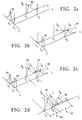
- Figs. 2a-d are plots showing the individual spectral components of a combined emission spectrum.
- Fig. 3 is a schematic block diagram of a first variation of the device of Fig. 1 featuring dual lock-in amplifiers for each detector.
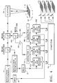
- Fig. 4 is a schematic block diagram of a second variation of the device of Fig. 1 featuring dual lock-in amplifiers for each detector configured for phase discrimination as well as frequency discrimination.
- Fig. 5 is a schematic block diagram of a single detector quantitative microfluorometer in accordance with the present invention.
- Figs. 6a-d are plots showing the individual spectral components of a combined emission spectrum.
- Figs. 7a-b are a diagrammatic representation of the phase relation between the modulated excitation wavelength and the modulated fluorescent emissions from two fluorophores for each of the lock-in amplifiers.
- Fig. 8 is a vector diagram of the phase angles of the components of the output of dual phase lock-in amplifier 1.
- Fig. 9 is a vector diagram showing the phase relationship of the components of the output of dual phase lock-in amplifier 2.
- Fig. 10 is a schematic block diagram of a variation of the second embodiment of the present invention using single phase lock-in amplifiers.
- a schematic block diagram of the first embodiment of the quantitative microfluorometer employing two excitation wavelengths, two detectors and two lock-in amplifiers is shown.
- Monochromatic excitation light of different wavelengths is supplied by a pair of light sources 12 and 14.
- light sources 12 and 14 are separate diode lasers, although any source of electromagnetic radiation capable of being time-modulated in intensity may be used.
- the intensity of light source 12 is controlled by a modulator 16 operating at a sinusoidal frequency ⁇ 1 .
- light source 14 is controlled by a second modulator 18 operating at frequency ⁇ 2 .
- the combination of light source 12 and modulator 16 may alternatively be implemented by a continuous gas laser, followed by an electro-optical or an acousto-optical modulator operating at a frequency ⁇ 1 .
- the combination of light source 14 and modulator 18 may be implemented by a continuous gas laser, followed by an electro-optical or acousto-optical modulator operating at a frequency ⁇ 2 .
- these modulators should be capable of operating at frequencies up to 50 Mhz to cover phase shift measurements according to one of the preferred embodiments. Realistic values of the modulation frequencies in the other embodiments are 2.2 and 3.0 Mhz. Individual light beams from light sources 12 and 14 are combined in a beam combiner 20.
- the combined beam passes through a beamsplitter 22, which transmits light at the excitation wavelengths ⁇ 1 and ⁇ 2 .
- a scanner 24 sequentially directs the combined beam to locations at sample 26.
- a realistic value of the sampling frequency of the scanner is 100 khz.
- scanner 24 is a confocal laser microscope, although any device capable of focusing excitation at, and collecting emitted radiation from, a discrete location in sample 26 may be used.
- Sample 26 may be any light-transmitting object containing multiple fluorophores. Such objects include biological cells and two dimensional gels used for separating compounds or dish cultures and the like.
- the combined fluorescence emitted in response to excitation at the focal point of scanner 24 is collected by scanner 24 and directed to beamsplitter 22, which has a dichroic element, then passed through another beamsplitter 102, which deflects emitted fluorescence to the two detectors 114 and 116.
- Detectors 114 and 116 may each be any device which produces a signal in response to the photons emitted by the fluorophores. Photomultipliers which convert photons into electrical signals are examples of such devices.
- the semi-reflecting element of the beamsplitter 102 may be a dichroic mirror, performing both beamsplitting and spectral separation.
- optical filters 104 and 106 may be employed.
- the effect of the optical filtering performed either by a dichroic element included in beamsplitter 102 or by optical filters 104 and 106, or jointly by these elements, is to separate the collected light into two parts representing different wavelength bands. These parts are distributed to detectors 114 and 116, respectively. Detectors 114 and 116 may be any detectors which produce an electrical signal in response to photons emitted by the fluorophores. Photomultipliers, which convert photons into electrical signals, are examples of such devices.
- the signals produced by detectors 114 and 116 are sent to a pair of lock-in amplifiers 30 and 32.
- Lock-in amplifier 30 is synchronized with the modulation frequency ⁇ 1 imposed on light source 12 by modulator 16.
- lock-in amplifier 32 is synchronized with the modulation frequency ⁇ 2 imposed on light source 14 by modulator 18. The phase position of each lock-in amplifier is adjusted to maximize the output.
- the curves show the individual spectral components of a combined emission spectrum emitted by two fluorophores in response to excitation by two wavelengths.
- the curves approximately describe the spectra of two commonly used fluorophores, TRITC (tetramethyl rhodamine isothiocyanate) (fluorophore A) and Lucifer Yellow (fluorophore B).
- TRITC tetramethyl rhodamine isothiocyanate
- fluorophore A tetramethyl rhodamine isothiocyanate
- Lucifer Yellow fluorophore B
- Fluorophore A produces a fluorescent emission spectrum 46 (I A ) in response to ⁇ 1 .
- Fluorophore B produces a fluorescent emission spectrum 50 (I B ) in response to ⁇ 2 and a smaller fluorescent emission spectrum 52 (I b ) in response to ⁇ 1 .
- This latter cross-excited spectrum results from the fact that absorption spectra 42 and 44 overlap at the wavelength ⁇ 1 .
- the combined emission spectrum, in response to excitation by ⁇ 1 and ⁇ 2 is composed of the superimposed spectra 46 (I A ), 50 (I B ) and 52 (I b ), as indicated by Fig. 4d.
- the contribution 50 (I B ) is the only of the three emissions that is modulated with the frequency ⁇ 2 .
- the wavelength band 62 (b) deflected to detector 116 (detector 2) is chosen so as to encompass the major part of the spectral range of contribution 50 (I B ).
- the measured value of the contribution I B is then obtained from the output of lock-in amplifier 32.
- the contributions 46 (I A ) and 52 (I b ) are both modulated with frequency ⁇ 1 .
- the wavelength band 60 (a) deflected to detector 114 (detector 1) is chosen so as to exclude the spectral range of contribution 52 (I b ) but to encompass the major part of contribution 46 (I A ).
- the measured value of the contribution I A is then obtained as an output from lock-in amplifier 30.
- the outputs from lock-in amplifiers 30 and 32 are sent to a computer 34.
- computer 34 is a digital computer and the outputs from amplifiers 30 and 32 are digitized, before storage, by conventional analog to digital converters.
- the inputs representing contributions I A and I B at discrete locations in sample 26 are stored in a location specific manner in the computer 34 and can be displayed as digital images on a screen.
- An image representing fluorophore A or an image representing fluorophore B can be displayed separately.
- an image representing the two fluorophores can be displayed simultaneously, e.g., using colors to distinguish them from each other.
- Computer 34 may also derive projection images of a stack of recorded images representing a three-dimensional transparent volume, such as a cell, marked by two different fluorophores, and display such projection images in a similar fashion on a screen.
- a stack of recorded images representing a three-dimensional transparent volume, such as a cell, marked by two different fluorophores
- displayed data representing measured values of I A and I B are mapped into digital images 72 and 78 for visualization.
- two lock-in amplifiers 122 and 124 have been provided for detector 114 (detector 1), and two lock-in amplifiers 126 and 128 for detector 116 (detector 2).
- Lock-in amplifiers 122 and 126 are locked to modulator 16 (modulator 1), and lock-in amplifiers 124 and 128 to modulator 18 (modulator 2).
- the phase position of each lock-in amplifier is adjusted to maximize the output.
- the wavelength band deflected to detector 116 is chosen so as to encompass the major part of the spectral range of contribution 50 (I B ). It will also encompass major parts of the cross-excited contribution 52 (I b ).
- the contribution 50 (I B ) is modulated with frequency ⁇ 2
- contribution 52 (I b ) is modulated with frequency ⁇ 1 .
- Lock-in amplifier 126 is locked to frequency ⁇ 1 and lock-in amplifier 128 to frequency ⁇ 2 .
- the measured value of the contribution 50 (I B ) is then obtained as an output from lock-in amplifier 128, separated from any of the other contributions, i.e., separated from contribution 52 (I b ) and from contribution 46 (I A ), which are both modulated with frequency ⁇ 1 .
- the measured value of the contribution 52 (I b ) is obtained as an output from lock-in amplifier 126, separated from contribution 50 (I B ), which is modulated with the frequency ⁇ 2 , and possibly with some interference from contribution 46 (I A ), the spectral range of which lies essentially in the wavelength band deflected to detector 114 (detector 1). If this interference is not negligible, it can be compensated for, as will be explained below.
- the wavelength band deflected to detector 114 (detector 1) is chosen so as to exclude the spectral range of contribution 52 (I b ) but to encompass the major part of contribution 46 (I A ), modulated with frequency ⁇ 1 .
- the measured value of the contribution 46 (I A ) is obtained as an output from lock-in amplifier 122, which is tuned to frequency ⁇ 1 , separated from all other a contributions, including contribution 50 (I B ), which is modulated with the frequency ⁇ 2 .
- the measured value of the contribution 46 (I A ) does not include the minor part of that contribution which is deflected to detector 116 (detector 2).
- this minor part which by an estimable amount is proportional to the measured part deflected to detector 114 (detector 1), is not negligible, it can be obtained directly as a proportion of the measured part of contribution 46 (I A ) obtained from detector 114 (detector 1).
- measured values from detector 116 (detector 2) can be corrected for the interference from contribution 46 (I A ) by subtracting this proportion. This operation is preferably performed by computer 34.
- lock-in amplifier 124 tuned to frequency ⁇ 2 , is to provide an output which is a measured value of a possible contribution I a , representing a cross-excited contribution from fluorophore A excited by wavelength ⁇ 2 .
- This contribution will occur if absorption spectra 42 and 44 overlap also at wavelength ⁇ 2 .
- the main part of the contribution I a if occurring, is located within the spectral range 60 (a) passed to detector 114.
- the outputs from lock-in amplifiers 122, 124, 126 and 128 are sent to a computer 34.
- the inputs to computer 34 representing contributions I A , I a , I b and I B , respectively, at discrete locations in sample 26 are stored in a location specific manner in the computer 34 and can be displayed as digital images on a screen. As explained in the description of the previous embodiment, they can be displayed separately or in combinations and in projection images from a volume.
- quotient images can be presented, representing I a /I A or I b /I B , conveying information about the shape of the excitation spectra of fluorophores A and B, respectively.
- stored data representing measured values of I A , I a , I b and I B are mapped into digital images 72, 74, 76 and 78 for visualization.
- FIG. 4 A variation of the apparatus of Fig. 3 is shown in Fig. 4, where lock-in amplifiers 122 and 124 are both locked to modulator 16, and lock-in amplifiers 126 and 128 are both locked to modulator 18.
- the phase position of amplifier 124 is shifted 90° relatively to the phase position of amplifier 122 and the phase position of amplifier 128 is shifted 90° relatively to that of amplifier 126.
- amplifiers 122 and 124 constitute a two-phase lock-in amplifier with an in-line and a quadrature channel.
- amplifiers 126 and 128 also constitute such an amplifier.
- the outputs I' and I" of a two-phase lock-in amplifier constitute the x and y components of a vector, which, in polar coordinates, represents the magnitude and the phase angle of the signal applied to the amplifier.
- the transformation to obtain this magnitude and this phase angle from each two-phase lock-in amplifier is performed by the computer 34.
- phase angle apart from an off-set that can be eliminated by adjustment of the two-phase lock-in amplifier, represents the phase shift between the waveform of the modulated excitation and the waveform of the detected emission.
- modulation frequencies 2.2 and 3.0 Mhz and with fluorophores that are commonly used for labeling the phase angle shift will be very small, on the order of a few degrees. It will not change substantially from one location of the specimen to another. Therefore, the adjustment of the phase position of a lock-in amplifier to maximize the output is generally quite uncritical. This kind of adjustment has to be performed when using the lock-in amplifiers in the embodiments described earlier. If modulation frequencies are used that are much higher and/or fluorophores are used that have long decay times, substantial phase shifts may appear.
- phase shift ⁇ A of fluorophore A is derived by the computer 34
- phase shift ⁇ B of fluorophore B is derived by the computer 34.
- the magnitude derived by the computer from the outputs of amplifiers 122 and 124 is the measured value of the emission spectrum I A , isolated from other contributions to the total emission in an identical way as described in the specification of the embodiment according to Fig. 1.
- the magnitude derived by the computer from the outputs of amplifiers 126 and 128 is the measured value of the emission spectrum I B .
- decay times for each pixel of a scanned image can be calculated and displayed, supplying, in addition to an intensity image of the fluorophore, also a decay time image, alternatively referred to, in the literature, as a "Fluorescence Lifetime Image". This is performed, simultaneously and independently, for two fluorophores, A and B.
- stored data representing measured values of I A , ⁇ A , I B and ⁇ B are mapped into digital images 72, 73, 78, and 79 for visualization.
- a schematic block diagram of the second embodiment of the quantitative microfluorometer employing two excitation wavelengths, a single detector and two dual phase lock-in amplifiers is shown.
- monochromatic excitation light of different wavelengths is supplied by a pair of light sources 12 and 14.
- the intensity of light source 12 is controlled by a modulator 16 operating at a sinusoidal frequency ⁇ 1
- light source 14 is controlled by a second modulator 18 operating at a separate frequency ⁇ 2 .
- modulators 16 and 18 are electro-optical modulators or acousto-optical modulators operating at frequencies up to 50 Mhz.
- any modulator capable of operating at frequencies preferably at least two times greater than the sampling frequency of the microfluorometer may be substituted.
- individual light beams from light sources 12 and 14 are combined in beam combiner 20, the combined beam passes through beamsplitter 22 which transmits light at the excitation wavelengths ⁇ 1 and ⁇ 2 , and scanner 24 sequentially directs the combined beam to locations within sample 26.
- the combined fluorescence emitted in response to excitation at the focal point of scanner 24 is collected by scanner 24 and directed to beamsplitter 22.
- detector 28 takes the place of detectors 114 and 116 that were used in the dual detector embodiment of Fig. 1.
- the second beamsplitter 102 is also not used in this embodiment.
- Detector 28 collects the emitted fluorescence which has been deflected from beamsplitter 22.
- the signal produced by detector 28 is sent to a pair of lock-in amplifiers 30 and 32.
- Lock-in amplifier 30 is synchronized with the modulation frequency ⁇ 1 imposed on light source 12 by modulator 16.
- lock-in amplifier 32 is synchronized with the modulation frequency ⁇ 2 imposed on light source 14 by modulator 18.
- lock-in amplifiers 30 and 32 are dual phase amplifiers producing two outputs which represent amplitudes of the recorded waveform at phase positions that are 90° apart.
- the outputs from lock-in amplifiers 30 and 32 are sent to a computer 34.
- Computer 34 stores the inputs corresponding to each discrete location in sample 26 in a location specific manner and mathematically reconstructs the individual spectral components corresponding to the excitation of each fluorophore by each wavelength.
- computer 34 is a digital computer and the outputs from amplifiers 30 and 32 are digitized, before storage, by conventional analog to digital converters.
- ⁇ 1 and ⁇ 2 are selected by examining the absorption spectra 142 and 144 of fluorophores A and B respectively. ⁇ 1 is chosen to predominantly excite fluorophore A, while ⁇ 2 is chosen to predominantly excite fluorophore B. Fluorophore A produces a main fluorescent emission spectrum 146 (I A1 ) in response to ⁇ 1 and a smaller cross-excited fluorescent emission spectrum 148 (I A2 ) in response to ⁇ 2 . This results from the fact that absorption spectra 142 and 144 overlap.
- fluorophore B produces a main fluorescent emission spectrum 150 (I B2 ) in response to ⁇ 2 and a smaller cross-excited fluorescent emission spectrum 152 (I B1 ) in response to ⁇ 1 .
- Excitation at wavelength ⁇ 1 produces a combined response 154, which is the sum of fluorophore A main response 146 and fluorophore B cross-excited response 152 (I A1 + I B1 ).
- excitation at wavelength ⁇ 2 produces a combined response 156 consisting of fluorophore B main response 150 and fluorophore A cross-excited response 148 (I B2 + I A2 ).
- a combined emission spectrum 140 in response to excitation by ⁇ 1 and ⁇ 2 , is composed of the sum of emission spectra 146, 148, 152 and 150 (I A1 + I A2 + I B1 + I B2 ).
- Figs. 7a-b the phase relationship between waveforms of the modulated excitation beams and the corresponding emitted fluorescence is shown.
- the intensity modulation of the beam having excitation wavelength ⁇ 1 is represented by a sinusoidal waveform 160.
- Fluorophore A responds to ⁇ 1 with a sinusoidally modulated fluorescent main signal 162.
- Fluorophore B also responds to ⁇ 1 with a smaller modulated fluorescent cross-excited signal 164.
- the frequencies of excitation signal 160 and fluorescent signals 162 and 164 are the same and will be captured by lock-in amplifier 30 which is synchronized with the modulation frequency ⁇ 1 of ⁇ 1 .
- the phase of the emitted fluorescence waveform will differ from that of the excitation waveform.
- the phase relationship between the emitted fluorescence waveform and the excitation waveform is dependent upon the fluorescent relaxation time of the individual fluorophores and on the modulation frequency.
- Lock-in amplifier 32 is synchronized with the modulation frequency ⁇ 2 of ⁇ 2 .
- Fluorophore B which is predominantly excited by ⁇ 2 , emits a modulated fluorescent main signal 168 while fluorophore A emits a smaller modulated fluorescent cross-excited signal 170.
- Fluorescent signals 168 and 170 have the same frequency as excitation 166 and are captured by lock-in amplifier 32. The phases of the emitted fluorescent signals 168 and 170 however will differ from the phase of excitation 166.
- Figs. 8 and 9 the vector components and phase angles of the in-phase and quadrature channels of lock-in amplifiers 30 and 32, respectively, are shown.
- the output of the in-phase channel is represented by the quantity I 1 ' and the output of the quadrature channel is represented by the quantity I 1 ".
- the input to amplifier 30 is represented by a vector of amplitude I 1 at a phase angle V 1 to the in-phase channel. This is composed of the vector sum of the signals corresponding to each fluorophore represented by I A1 at an angle V A1 for fluorophore A and I B1 at angle V B1 for fluorophore B. Similar notation is used in Fig. 9 with the subscript 2 replacing the subscript 1 for the components of lock-in amplifier 32.
- the following equations are used in computer 34 to resolve the outputs of amplifiers 30 and 32 into the component vectors for fluorophores A and B:
- phase position of the in-phase channel is tuned to be close to the position that gives a maximum value for the output from the predominantly excited fluorophore.
- Lock-in amplifier 30 is thus tuned to detect signals from fluorophore A predominantly while lock-in amplifier 32 is tuned to detect signals from fluorophore B predominantly.
- computer 34 is able to solve the four simultaneous equations (El) having four unknowns, I A1 , I A2 , I B1 and I B2 , using conventional numerical techniques.
- the derived quantities, I A1 , I A2 , I B1 and I B2 representing the individual components of combined emission spectrum 140 are digitally stored in the memory of computer 34 for each location scanned in specimen 26.
- the data may be output by computer 34 as displayed images 172, 174, 176 and 178, shown in Fig. 5, corresponding to components I A1 , I B2 , I A2 and I B1 , respectively, or used for further processing.
- Fig. 10 a schematic block diagram of a variation of the second embodiment of the invention, employing single phase lock-in amplifiers, is shown.
- the phase position of lock-in amplifier 30, which picks up emission predominantly from fluorophore A is tuned to the position which cancels out the contribution from the waveform generated by fluorophore B.
- the phase position of lock-in amplifier 32, which picks up emission predominantly from fluorophore B is tuned to the position that cancels out the contribution from the waveform generated by fluorophore A. Regions where one fluorophore is present and the other is not are determined by direct observation.
- Such regions can be determined by scanning the data set for minimum values of the quotients I 2 /I 1 and I 1 /I 2 , In cases where the fluorophores A and B have different relaxation times, computer 34 is only able to derive the quantities I A1 and I B2 , representing individual components of combined emission spectrum 140.
- the data may be output by computer 34 as displayed image 172 for I A1 from fluorophore A and 174 for I B2 from fluorophore B.
- the fluorophores used were TRITC and Lucifer Yellow, at 514 and 458 nm, respectively. These fluorophores were modulated at 0.7 MHz and 0.9 MHz, respectively, using two argon-ion lasers of about 1 watt output power each. The pixel sampling rate was 100 KHz.
- the ability of the present invention to quantify multiple fluorophores simultaneously may be utilized in a variety of applications. These include the quantitative analysis of fluorescently labeled compounds which have been electrophoretically separated, such as the individual bases in a DNA sequencing. Additionally, the kinetics of reactions involving fluorescently labeled compounds in intact cells may be followed. For example, regions where the fluorescent relaxation times take specific values may be extracted from recorded images. This would open a completely new way to analyze and quantify microscopic structures in three dimensions.
Landscapes
- Health & Medical Sciences (AREA)
- Chemical & Material Sciences (AREA)
- Immunology (AREA)
- Physics & Mathematics (AREA)
- General Physics & Mathematics (AREA)
- Analytical Chemistry (AREA)
- Biochemistry (AREA)
- General Health & Medical Sciences (AREA)
- Life Sciences & Earth Sciences (AREA)
- Nuclear Medicine, Radiotherapy & Molecular Imaging (AREA)
- Pathology (AREA)
- Chemical Kinetics & Catalysis (AREA)
- Optics & Photonics (AREA)
- Investigating, Analyzing Materials By Fluorescence Or Luminescence (AREA)
- Investigating Or Analysing Materials By Optical Means (AREA)
- Spectrometry And Color Measurement (AREA)
- Investigating Or Analysing Materials By The Use Of Chemical Reactions (AREA)
Claims (24)
- Dispositif pour quantifier des cibles fluorescentes par excitation au moyen d'une radiation électromagnétique présentant de multiples longueurs d'onde discrètes, comprenant :des moyens pour diriger des rayons doubles de radiation électromagnétique continue, chaque rayon présentant une longueur d'onde discrète, cependant que lesdits rayons se rencontrent de manière à produire un balayage en une pluralité d'endroits individuels où des cibles fluorescentes sont présentes, en provoquant l'excitation de celles-ci ;des moyens pour moduler l'intensité de chacun desdits rayons à des fréquences de modulation séparées pour donner à chacun desdits rayons une forme d'onde spécifique modulée dans le temps ;des moyens pour détecter l'émission fluorescente combinée provenant desdites cibles en réponse à ladite excitation ; et :des moyens de démodulation comprenant au moins deux amplificateurs de blocage, chaque amplificateur étant associé à une fréquence de modulation différente, pour extraire de ladite émission fluorescente combinée détectée les contributions qui correspondent à chacune desdites cibles, en quantifiant ainsi lesdites cibles.
- Dispositif selon la revendication 1, dans lequel lesdits moyens pour détecter l'émission fluorescente combinée provenant desdites cibles comprennent des détecteurs doubles.
- Dispositif selon la revendication 1, dans lequel lesdits moyens pour détecter l'émission fluorescente combinée provenant desdites cibles comprennent un détecteur unique.
- Dispositif pour quantifier des cibles fluorescentes distribuées dans un plan de l'espace par excitation au moyen d'une radiation électromagnétique présentant de multiples longueurs d'onde discrètes, comprenant :des moyens pour diriger des rayons doubles de radiation électromagnétique présentant des longueurs d'onde discrètes différentes vers une pluralité d'endroits individuels de manière à produire un balayage dans un plan où des cibles fluorescentes sont présentes, en provoquant l'excitation des cibles ;des moyens pour moduler chacun desdits rayons à des fréquences de modulation séparées pour donner à chacun desdits rayons une forme d'onde spécifique modulée dans le temps ;des moyens pour recueillir la radiation émise en des endroits dudit plan en réponse à ladite excitation ;des moyens pour séparer optiquement des parties du spectre de ladite radiation émise, lesdites parties du spectre représentant au moins deux bandes de longueurs d'onde différentes ;des moyens pour détecter indépendamment la radiation qui représente chacune desdites parties séparées du spectre de ladite radiation émise ;des moyens de démodulation comprenant au moins deux amplificateurs de blocage, chaque amplificateur étant associé à une fréquence de modulation différente, pour extraire de chacune desdites parties détectées du spectre de la radiation combinée émise depuis des cibles fluorescentes multiples les contributions qui correspondent à chacune desdites cibles, en quantifiant ainsi chaque cible dans ledit plan.
- Dispositif selon la revendication 4, dans lequel chacun desdits rayons est produit par une diode laser séparée, chacune desdites diodes laser étant modulée en intensité à une fréquence séparée.
- Dispositif selon la revendication 4, dans lequel lesdits moyens pour moduler chacun desdits rayons comprennent un modulateur optoélectrique pour chaque rayon, chacun des rayons étant modulé à une fréquence séparée.
- Dispositif selon la revendication 4, dans lequel lesdits moyens pour moduler chacun desdits rayons comprennent un modulateur optoacoustique pour chaque rayon, chacun des rayons étant modulé à une fréquence séparée.
- Dispositif selon la revendication 4, dans lequel lesdits moyens pour détecter indépendamment des parties du spectre de ladite émission combinée comprennent des détecteurs doubles, et lesdits moyens pour séparer optiquement des parties du spectre comprennent des filtres optiques susceptibles de distribuer à chacun desdits détecteurs doubles des parties de spectre séparées de ladite émission fluorescente combinée.
- Dispositif selon la revendication 8, dans lequel lesdits moyens de démodulation comprennent des moyens de démodulation séparés pour chacun desdits détecteurs doubles, lesdits moyens de démodulation étant propres à des signaux présentant les mêmes fréquences que la fréquence de modulation d'un rayon correspondant, et le signal de sortie de chaque moyen de démodulation étant propre à une position particulière de la phase de la forme d'onde modulée.
- Dispositif selon la revendication 9, dans lequel lesdits moyens de démodulation comprennent un amplificateur de blocage à phase unique pour chacun des détecteurs doubles, ledit amplificateur étant synchronisé avec la fréquence de modulation du rayon correspondant.
- Dispositif selon la revendication 10, dans lequel la position de la phase de chacun desdits amplificateurs à phase unique est accordée sur la position qui rend maximal le signal de sortie dudit amplificateur provenant d'une cible fluorescente correspondante.
- Dispositif selon la revendication 9, dans lequel lesdits moyens de démodulation comprennent deux amplificateurs de blocage à phase unique pour chacun desdits détecteurs doubles, l'un étant synchronisé avec la fréquence de modulation de l'un desdits rayons d'excitation et l'autre l'étant avec la fréquence de modulation de l'autre, des spectres à excitation croisée étant mesurés simultanément et indépendamment.
- Dispositif selon la revendication 9, dans lequel lesdits moyens de démodulation comprennent un amplificateur de blocage à phase double pour chacun desdits détecteurs doubles, des déphasages de deux cibles fluorescentes étant mesurés simultanément et indépendamment.
- Dispositif selon la revendication 4, dans lequel lesdits moyens pour recueillir la radiation émise en des endroits dudit plan est un microscope à foyer commun.
- Dispositif pour quantifier des cibles fluorescentes distribuées dans un volume de l'espace par excitation au moyen d'une radiation électromagnétique présentant de multiples longueurs d'onde discrètes, comprenant :des moyens pour diriger des rayons doubles de radiation électromagnétique présentant des longueurs d'onde discrètes différentes vers une pluralité d'endroits individuels de manière à produire un balayage sur un plan de balayage d'un échantillon volumique où une ou plusieurs cibles fluorescentes sont présentes, en provoquant l'excitation de la cible ;des moyens pour moduler chacun desdits rayons à des fréquences de modulation séparées pour donner à chacun desdits rayons une forme d'onde spécifique modulée dans le temps ;des moyens à foyer commun pour recueillir la radiation émise en des endroits du plan de balayage en réponse à ladite excitation ;des moyens pour séparer optiquement des parties du spectre de ladite radiation émise, lesdites parties du spectre représentant au moins deux bandes de longueurs d'onde différentes ;des moyens pour détecter indépendamment la radiation qui représente chacune desdites parties séparées du spectre de ladite radiation émise ;des moyens de démodulation comprenant au moins deux amplificateurs de blocage, chaque amplificateur étant associé à une fréquence de modulation différente, pour extraire de chacune desdites parties détectées du spectre de la radiation combinée émise depuis des cibles fluorescentes multiples les contributions qui correspondent à chacune desdites cibles, en quantifiant ainsi chaque cible sur le plan de balayage ;des moyens pour remplacer le plan de balayage par un autre plan de balayage de l'échantillon volumique ; et :des moyens pour mettre en mémoire des données pour une pluralité de plans de balayage représentant la quantification de cibles fluorescentes dans un échantillon volumique.
- Dispositif selon la revendication 15, dans lequel chacun desdits rayons est produit par une diode laser séparée, chacune desdites diodes laser étant modulée à une fréquence séparée.
- Dispositif selon la revendication 15, dans lequel lesdits moyens pour moduler chacun desdits rayons comprennent un modulateur optoélectrique pour chaque rayon.
- Dispositif selon la revendication 15, dans lequel lesdits moyens pour moduler chacun desdits rayons comprennent un modulateur optoacoustique pour chaque rayon.
- Dispositif selon la revendication 15, dans lequel lesdits moyens pour détecter indépendamment des parties du spectre de ladite émission combinée comprennent des détecteurs doubles, et lesdits moyens pour séparer optiquement les parties du spectre comprennent des filtres optiques susceptibles de distribuer à chacun desdits détecteurs doubles des parties de spectre séparées de ladite émission fluorescente combinée.
- Dispositif selon la revendication 19, dans lequel lesdits moyens de démodulation comprennent des moyens de démodulation séparés pour chacun desdits détecteurs doubles, lesdits moyens de démodulation étant propres à des signaux présentant les mêmes fréquences que la fréquence de modulation d'un rayon correspondant, et le signal de sortie de chaque moyen de démodulation étant propre à une position particulière de la phase de la forme d'onde modulée.
- Dispositif selon la revendication 20, dans lequel lesdits moyens de démodulation comprennent un amplificateur de blocage à phase unique pour chacun des détecteurs doubles, ledit amplificateur étant synchronisé avec la fréquence de modulation du rayon correspondant.
- Dispositif selon la revendication 21, dans lequel la position de la phase de chacun desdits amplificateurs à phase unique est accordée sur la position qui rend maximal le signal de sortie dudit amplificateur provenant d'une cible fluorescente correspondante.
- Dispositif selon la revendication 20, dans lequel lesdits moyens de démodulation comprennent deux amplificateurs de blocage à phase unique pour chacun desdits détecteurs doubles, l'un étant synchronisé avec la fréquence de modulation de l'un desdits rayons d'excitation et l'autre l'étant avec la fréquence de modulation de l'autre, des spectres à excitation croisée étant mesurés simultanément et indépendamment.
- Dispositif selon la revendication 20, dans lequel lesdits moyens de démodulation comprennent un amplificateur de blocage à phase double pour chacun desdits détecteurs doubles, des déphasages de deux cibles fluorescentes étant mesurés simultanément et indépendamment.
Applications Claiming Priority (5)
| Application Number | Priority Date | Filing Date | Title |
|---|---|---|---|
| US08/011,881 US5294799A (en) | 1993-02-01 | 1993-02-01 | Apparatus for quantitative imaging of multiple fluorophores |
| US11881 | 1993-02-01 | ||
| US189190 | 1994-01-31 | ||
| US08/189,190 US5418371A (en) | 1993-02-01 | 1994-01-31 | Apparatus for quantitative imaging of multiple fluorophores using dual detectors |
| PCT/IB1994/000019 WO1994018547A1 (fr) | 1993-02-01 | 1994-02-01 | Appareil d'imagerie quantitative de fluorogenes multiples |
Publications (2)
| Publication Number | Publication Date |
|---|---|
| EP0681695A1 EP0681695A1 (fr) | 1995-11-15 |
| EP0681695B1 true EP0681695B1 (fr) | 1997-05-02 |
Family
ID=26682894
Family Applications (1)
| Application Number | Title | Priority Date | Filing Date |
|---|---|---|---|
| EP94906355A Expired - Lifetime EP0681695B1 (fr) | 1993-02-01 | 1994-02-01 | Appareil d'imagerie quantitative de fluorogenes multiples |
Country Status (6)
| Country | Link |
|---|---|
| US (1) | US5418371A (fr) |
| EP (1) | EP0681695B1 (fr) |
| JP (1) | JPH08506419A (fr) |
| AT (1) | ATE152519T1 (fr) |
| DE (1) | DE69402958T2 (fr) |
| WO (1) | WO1994018547A1 (fr) |
Cited By (3)
| Publication number | Priority date | Publication date | Assignee | Title |
|---|---|---|---|---|
| DE10054426A1 (de) * | 2000-10-27 | 2002-05-02 | Iom Innovative Optische Mestec | Verfahren zur Multi-Fluoreszenz-Detektion |
| CN105043995A (zh) * | 2015-04-23 | 2015-11-11 | 天津大学 | 一种位置正弦波频率编码的阵列式透射光测量系统 |
| DE102004017956B4 (de) | 2004-04-14 | 2022-07-07 | Leica Microsystems Cms Gmbh | Verfahren zur Untersuchung der Lebensdauer angeregter Zustände in einer Probe |
Families Citing this family (86)
| Publication number | Priority date | Publication date | Assignee | Title |
|---|---|---|---|---|
| CH697814B1 (de) * | 2001-01-26 | 2009-02-27 | Tecan Trading Ag | Optisches System und Verfahren zum Anregen und Messen von Fluoreszenz an oder in mit Fluoreszenzfarbstoffen behandelten Proben. |
| CN1149335A (zh) * | 1994-05-27 | 1997-05-07 | 希巴-盖吉股份公司 | 探测短暂受激发光的方法 |
| US5735276A (en) * | 1995-03-21 | 1998-04-07 | Lemelson; Jerome | Method and apparatus for scanning and evaluating matter |
| US5675155A (en) * | 1995-04-26 | 1997-10-07 | Beckman Instruments, Inc. | Multicapillary fluorescent detection system |
| US5793049A (en) * | 1995-07-06 | 1998-08-11 | Yale University | Optical filtering and spectroscopic imaging |
| DE19536296B4 (de) * | 1995-09-29 | 2004-10-14 | Daimlerchrysler Ag | Signalmarken und Verfahren zu deren Identifizierung |
| US5784157A (en) * | 1995-11-21 | 1998-07-21 | The Research Foundation Of State University Of New York | Method and apparatus for identifying fluorophores |
| AU2990097A (en) * | 1996-01-11 | 1997-08-20 | Trustees Of Princeton University, The | Organic luminescent coating for light detectors |
| US5851488A (en) * | 1996-02-29 | 1998-12-22 | Biocircuits Corporation | Apparatus for automatic electro-optical chemical assay determination |
| AT403745B (de) * | 1996-02-29 | 1998-05-25 | Avl Verbrennungskraft Messtech | Messanordnung mit einem für anregungs- und messstrahlung transparentem trägerelement |
| DE69730562T2 (de) * | 1996-06-18 | 2005-10-13 | Fuji Photo Film Co., Ltd., Minami-Ashigara | Bildlesegerät |
| DE19634873A1 (de) * | 1996-08-29 | 1998-03-12 | Boehringer Mannheim Gmbh | System zur Unterscheidung fluoreszierender Molekülgruppen durch zeitaufgelöste Fluoreszenzmessung |
| DE19722630C2 (de) * | 1997-05-30 | 1999-09-16 | Stiftung Fuer Lasertechnologie | Verfahren zur in situ Messung mitochondrialer Stoffwechselprodukte |
| US5986271A (en) * | 1997-07-03 | 1999-11-16 | Lazarev; Victor | Fluorescence imaging system |
| US6071748A (en) * | 1997-07-16 | 2000-06-06 | Ljl Biosystems, Inc. | Light detection device |
| US6097025A (en) * | 1997-10-31 | 2000-08-01 | Ljl Biosystems, Inc. | Light detection device having an optical-path switching mechanism |
| US6469311B1 (en) | 1997-07-16 | 2002-10-22 | Molecular Devices Corporation | Detection device for light transmitted from a sensed volume |
| GB9717021D0 (en) * | 1997-08-12 | 1997-10-15 | Kalibrant Limited | A detector |
| US6982431B2 (en) | 1998-08-31 | 2006-01-03 | Molecular Devices Corporation | Sample analysis systems |
| US6992761B2 (en) * | 1997-09-20 | 2006-01-31 | Molecular Devices Corporation | Broad range light detection system |
| US6576476B1 (en) | 1998-09-02 | 2003-06-10 | Ljl Biosystems, Inc. | Chemiluminescence detection method and device |
| US6326605B1 (en) | 1998-02-20 | 2001-12-04 | Ljl Biosystems, Inc. | Broad range light detection system |
| US6297018B1 (en) | 1998-04-17 | 2001-10-02 | Ljl Biosystems, Inc. | Methods and apparatus for detecting nucleic acid polymorphisms |
| WO2000006990A2 (fr) | 1998-07-27 | 2000-02-10 | Ljl Biosystems, Inc. | Appareil et des procedes de mesures spectroscopiques a resolution temporelle |
| US6825921B1 (en) | 1999-11-10 | 2004-11-30 | Molecular Devices Corporation | Multi-mode light detection system |
| US6091563A (en) * | 1997-09-26 | 2000-07-18 | Iomega Corporation | Latent illuminance discrimination marker system for data storage cartridges |
| WO1999042884A1 (fr) * | 1998-02-19 | 1999-08-26 | Leica Microsystems Heidelberg Gmbh | Systeme optique a element spectroselectif |
| DE19829981C2 (de) | 1998-07-04 | 2002-10-17 | Zeiss Carl Jena Gmbh | Verfahren und Anordnung zur konfokalen Mikroskopie |
| AU5223899A (en) | 1998-07-27 | 2000-02-21 | Ljl Biosystems, Inc. | Apparatus and methods for spectroscopic measurements |
| US6528801B1 (en) * | 1998-11-04 | 2003-03-04 | The Research Foundation Of State University Of New York | Method and apparatus for detecting radiation |
| US6455861B1 (en) * | 1998-11-24 | 2002-09-24 | Cambridge Research & Instrumentation, Inc. | Fluorescence polarization assay system and method |
| US6157037A (en) * | 1998-12-04 | 2000-12-05 | Photosense, Llc | Sensing device and method for measuring emission time delay during irradiation of targeted samples |
| DE19936573A1 (de) * | 1998-12-22 | 2001-02-08 | Zeiss Carl Jena Gmbh | Anordnung zur Separierung von Anregungs- und Emissionslicht in einem Mikroskop |
| US6320196B1 (en) | 1999-01-28 | 2001-11-20 | Agilent Technologies, Inc. | Multichannel high dynamic range scanner |
| AU3005400A (en) | 1999-02-23 | 2000-09-14 | Ljl Biosystems, Inc. | Frequency-domain light detection device |
| DE19915137C2 (de) * | 1999-03-26 | 2001-10-18 | Michael Schaefer | Verfahren zur Quantifizierung mehrerer Fluorochrome in einer mehrfach gefärbten Probe bei der Fluoreszenzmikroskopie und Verwendungen des Verfahrens |
| WO2001009592A1 (fr) | 1999-07-30 | 2001-02-08 | California Institute Of Technology | Systeme et procede de controle de l'activite cellulaire |
| DE10001954B4 (de) * | 1999-11-22 | 2004-07-22 | Leica Microsystems Heidelberg Gmbh | Laserscanmikroskop |
| US6329661B1 (en) * | 2000-02-29 | 2001-12-11 | The University Of Chicago | Biochip scanner device |
| DE10038080A1 (de) * | 2000-08-04 | 2002-02-21 | Giesing Michael | Verfahren und Vorrichtung zum ortsaufgelösten fluoreszenzoptischen Nachweis von auf einer Oberfläche eines planaren Trägers immobilisierten Substanzen |
| DE10038526B4 (de) * | 2000-08-08 | 2004-09-02 | Carl Zeiss Jena Gmbh | Verfahren und Anordnung zur Erfassung des wellenlängenabhängigen Verhaltens einer beleuchteten Probe |
| DE10056384C2 (de) * | 2000-11-14 | 2003-06-05 | Leica Microsystems | Vorrichtung zur Messung der Lebensdauer eines angeregten Zustandes in einer Probe und Verwendung der Vorrichtung |
| EP1351048A4 (fr) * | 2000-12-14 | 2007-02-28 | Olympus Corp | Analyseur fluorometrique et analyse fluorometrique |
| JP2002310894A (ja) * | 2001-04-11 | 2002-10-23 | Japan Science & Technology Corp | 発光観測装置、発光体選別装置、及び発光体の選別方法 |
| DE10144435B4 (de) * | 2001-09-06 | 2005-03-24 | EuroPhoton GmbH Gesellschaft für optische Sensorik | Verfahren zur Charakterisierung der Eigenschaften von fluoreszierenden Proben, insbesondere lebenden Zellen und Geweben, in multi-well, in in-vitro Fluoreszenz-Assays, in DNA-Chips, Vorrichtungen zur Durchführung des Verfahrens und deren Verwendung |
| DE10151217B4 (de) * | 2001-10-16 | 2012-05-16 | Carl Zeiss Microlmaging Gmbh | Verfahren zum Betrieb eines Laser-Scanning-Mikroskops |
| US7211377B1 (en) | 2002-01-22 | 2007-05-01 | Microbiosystems, Limited Partnership | Method for detecting the presence of dormant cryptobiotic microorganisms |
| US7186990B2 (en) * | 2002-01-22 | 2007-03-06 | Microbiosystems, Limited Partnership | Method and apparatus for detecting and imaging the presence of biological materials |
| US6750006B2 (en) | 2002-01-22 | 2004-06-15 | Microbiosystems, Limited Partnership | Method for detecting the presence of microbes and determining their physiological status |
| JP3878033B2 (ja) * | 2002-02-28 | 2007-02-07 | シーケーディ株式会社 | 三次元計測装置 |
| US20070096039A1 (en) * | 2002-05-03 | 2007-05-03 | Rakesh Kapoor | Evaluation Of Multicomponent Mixtures Using Modulated Light Beams |
| WO2005075963A1 (fr) * | 2002-05-03 | 2005-08-18 | Rakesh Kapoor | Evaluation de melanges a plusieurs composants a l'aide de faisceaux de lumiere modules |
| JP4074136B2 (ja) * | 2002-05-29 | 2008-04-09 | 浜松ホトニクス株式会社 | 蛍光寿命分布画像測定装置およびその測定方法 |
| DE10225838B4 (de) | 2002-06-11 | 2021-10-21 | Leica Microsystems Cms Gmbh | Verfahren zur Scanmikroskopie, Scanmikroskop und Vorrichtung zum Codieren eines Beleuchtungslichtstrahles |
| DE10339784B4 (de) | 2002-08-28 | 2021-09-16 | Carl Zeiss Meditec Ag | Mikroskopiesystem und Mikroskopieverfahren |
| WO2004029566A1 (fr) * | 2002-09-26 | 2004-04-08 | Bio Techplex Corporation | Procede et dispositif de criblage comprenant une del a modulation de forme d'onde |
| JP3915651B2 (ja) * | 2002-10-09 | 2007-05-16 | 株式会社島津製作所 | 複数の蛍光物質を含む試料の分析方法及び装置 |
| US7308157B2 (en) * | 2003-02-03 | 2007-12-11 | Photon Dynamics, Inc. | Method and apparatus for optical inspection of a display |
| JP4224640B2 (ja) * | 2004-03-29 | 2009-02-18 | オリンパス株式会社 | 蛍光分光分析装置 |
| US7006547B2 (en) * | 2004-03-31 | 2006-02-28 | Cymer, Inc. | Very high repetition rate narrow band gas discharge laser system |
| JP4539342B2 (ja) * | 2005-01-19 | 2010-09-08 | 株式会社ニコン | 解析装置、顕微鏡、および、解析プログラム |
| EP1845367A1 (fr) * | 2005-01-27 | 2007-10-17 | Nippon Sheet Glass Company, Limited | Procede de detection, microsysteme chimique utilisant le procede de detection, procede de detection de signal, systeme spectrophotometrique a lentille thermique, systeme de detection par fluorescence, dispositif de detection de signal, systeme de detection de signal, programme de detection de signal |
| KR100647317B1 (ko) * | 2005-02-03 | 2006-11-23 | 삼성전자주식회사 | 다채널 형광 측정용 광학계 및 이를 채용한 다채널 형광시료 분석 장치 |
| US7822558B2 (en) | 2005-02-15 | 2010-10-26 | Mitsui Engineering & Shipbuilding Co., Ltd. | Fluorescence detecting device and fluorescence detecting method |
| FR2884920B1 (fr) * | 2005-04-21 | 2007-08-10 | Horiba Abx Sa Sa | Dispositif et procede d'analyse multiparametrique d'elements microscopiques |
| DE102005022880B4 (de) * | 2005-05-18 | 2010-12-30 | Olympus Soft Imaging Solutions Gmbh | Trennung spektral oder farblich überlagerter Bildbeiträge in einem Mehrfarbbild, insbesondere in transmissionsmikroskopischen Mehrfarbbildern |
| GB0525072D0 (en) * | 2005-12-09 | 2006-01-18 | Enigma Diagnostics Ltd | Fluorescence-based detection methods and apparatus |
| US8063384B2 (en) | 2006-11-28 | 2011-11-22 | Nippon Sheet Glass Company, Limited | Detection system and probe therefor |
| US8110816B2 (en) | 2007-02-28 | 2012-02-07 | Nippon Sheet Glass Company, Limited | Fluorescence detection system |
| US8101426B2 (en) * | 2007-03-02 | 2012-01-24 | Icyt Mission Technology, Inc. | System and method for the measurement of multiple fluorescence emissions in a flow cytometry system |
| CA2754884C (fr) | 2007-06-21 | 2013-04-30 | Gen-Probe Incorporated | Methodes pour concentrer un analyte |
| US7675045B1 (en) * | 2008-10-09 | 2010-03-09 | Los Alamos National Security, Llc | 3-dimensional imaging at nanometer resolutions |
| KR101224976B1 (ko) * | 2009-01-22 | 2013-01-22 | 미쯔이 죠센 가부시키가이샤 | 형광 검출 장치 및 형광 검출 방법 |
| US8633432B2 (en) * | 2009-09-21 | 2014-01-21 | California Institute Of Technology | Reflective focusing and transmissive projection device |
| US20110218448A1 (en) * | 2010-03-03 | 2011-09-08 | Buntic Rudolf F | Perfusion detection devices and methods of using the same |
| DE102010019095B4 (de) | 2010-04-30 | 2016-12-08 | Deutsches Zentrum für Luft- und Raumfahrt e.V. | Verfahren und Vorrichtung zur Fluoreszenzlebensdauermessung |
| US8536545B2 (en) | 2010-09-09 | 2013-09-17 | California Institute Of Technology | Delayed emission detection devices and methods |
| EP2678664B1 (fr) | 2011-02-24 | 2019-08-07 | Gen-Probe Incorporated | Systèmes et procédés de distinction de signaux optiques de différentes fréquences de modulation dans un détecteur de signaux optiques |
| DE102011055294B4 (de) * | 2011-11-11 | 2013-11-07 | Leica Microsystems Cms Gmbh | Mikroskopische Einrichtung und Verfahren zur dreidimensionalen Lokalisierung von punktförmigen Objekten in einer Probe |
| DE102012019471B4 (de) * | 2012-09-28 | 2023-12-21 | Carl Zeiss Microscopy Gmbh | Vorrichtung und Verfahren zum Ermitteln von Stoffeigenschaften |
| EP3602003B1 (fr) | 2017-03-31 | 2026-04-22 | Life Technologies Corporation | Appareil, système et procédé pour cytométrie de flux par imagerie |
| US11041756B2 (en) | 2017-10-20 | 2021-06-22 | Charted Scientific Inc. | Method and apparatus of filtering light using a spectrometer enhanced with additional spectral filters with optical analysis of fluorescence and scattered light from particles suspended in a liquid medium using confocal and non confocal illumination and imaging |
| US10585028B2 (en) | 2017-10-20 | 2020-03-10 | Charted Scientific, Inc. | Method and apparatus for optical analysis |
| CN108801987B (zh) * | 2018-03-17 | 2021-03-23 | 杨佳苗 | 共焦分立荧光光谱及荧光寿命探测方法与装置 |
| DE102022122092A1 (de) * | 2022-08-31 | 2024-02-29 | Pyroscience Gmbh | Referenz-Messung |
| US20240319083A1 (en) * | 2023-03-20 | 2024-09-26 | The Board Of Regents Of The University Of Oklahoma | Apparatus for time-resolved fluorescence measurement using bandwidth-limited digital-pulse light modulation and methods |
Family Cites Families (6)
| Publication number | Priority date | Publication date | Assignee | Title |
|---|---|---|---|---|
| US4628026A (en) * | 1983-11-15 | 1986-12-09 | Dietlind Gardell | Method and apparatus for automated double fluorochromization analysis in lymphocytotoxicity testing |
| US4937457A (en) * | 1989-02-10 | 1990-06-26 | Slm Instruments, Inc. | Picosecond multi-harmonic fourier fluorometer |
| WO1992013265A1 (fr) * | 1991-01-24 | 1992-08-06 | The University Of Maryland | Procede et appareil d'imagerie multidimensionnelle a duree de vie de fluorescence a modulation de phase |
| US5208651A (en) * | 1991-07-16 | 1993-05-04 | The Regents Of The University Of California | Apparatus and method for measuring fluorescence intensities at a plurality of wavelengths and lifetimes |
| US5212386A (en) * | 1991-12-13 | 1993-05-18 | I.S.S. (U.S.A.) Inc. | High speed cross-correlation frequency domain fluorometry-phosphorimetry |
| US5294799A (en) * | 1993-02-01 | 1994-03-15 | Aslund Nils R D | Apparatus for quantitative imaging of multiple fluorophores |
-
1994
- 1994-01-31 US US08/189,190 patent/US5418371A/en not_active Expired - Fee Related
- 1994-02-01 DE DE69402958T patent/DE69402958T2/de not_active Expired - Fee Related
- 1994-02-01 WO PCT/IB1994/000019 patent/WO1994018547A1/fr not_active Ceased
- 1994-02-01 EP EP94906355A patent/EP0681695B1/fr not_active Expired - Lifetime
- 1994-02-01 JP JP6517853A patent/JPH08506419A/ja active Pending
- 1994-02-01 AT AT94906355T patent/ATE152519T1/de not_active IP Right Cessation
Cited By (4)
| Publication number | Priority date | Publication date | Assignee | Title |
|---|---|---|---|---|
| DE10054426A1 (de) * | 2000-10-27 | 2002-05-02 | Iom Innovative Optische Mestec | Verfahren zur Multi-Fluoreszenz-Detektion |
| DE10054426B4 (de) * | 2000-10-27 | 2006-03-09 | Iom Innovative Optische Messtechnik Gmbh | Verfahren zur Multi-Fluoreszenz-Detektion |
| DE102004017956B4 (de) | 2004-04-14 | 2022-07-07 | Leica Microsystems Cms Gmbh | Verfahren zur Untersuchung der Lebensdauer angeregter Zustände in einer Probe |
| CN105043995A (zh) * | 2015-04-23 | 2015-11-11 | 天津大学 | 一种位置正弦波频率编码的阵列式透射光测量系统 |
Also Published As
| Publication number | Publication date |
|---|---|
| WO1994018547A1 (fr) | 1994-08-18 |
| JPH08506419A (ja) | 1996-07-09 |
| US5418371A (en) | 1995-05-23 |
| EP0681695A1 (fr) | 1995-11-15 |
| DE69402958D1 (de) | 1997-06-05 |
| DE69402958T2 (de) | 1997-12-11 |
| ATE152519T1 (de) | 1997-05-15 |
Similar Documents
| Publication | Publication Date | Title |
|---|---|---|
| EP0681695B1 (fr) | Appareil d'imagerie quantitative de fluorogenes multiples | |
| US5294799A (en) | Apparatus for quantitative imaging of multiple fluorophores | |
| US5485530A (en) | Method and apparatus for multi-dimensional phase fluorescence lifetime imaging | |
| US5504337A (en) | Method and apparatus for performing phase fluorescence lifetime measurements in flow cytometry | |
| Wang et al. | Fluorescence lifetime imaging microscopy (FLIM): instrumentation and applications | |
| Piston et al. | Time-resolved fluorescence imaging and background rejection by two-photon excitation in laser-scanning microscopy | |
| Gadella Jr et al. | Fluorescence lifetime imaging microscopy (FLIM): spatial resolution of microstructures on the nanosecond time scale | |
| JP3712937B2 (ja) | スペクトル画像システムの較正のための装置及び方法 | |
| US7420674B2 (en) | Method and arrangement for analyzing samples | |
| Gadella Jr et al. | Fluorescence lifetime imaging microscopy: Pixel‐by‐pixel analysis of phase‐modulation data | |
| WO2007084945A1 (fr) | Systemes et procedes pour realiser des mesures rapides de durees de vies de la fluorescence, de l'excitation et de l'emission spectrale | |
| Clegg et al. | Fluorescence lifetime-resolved imaging microscopy: a general description of lifetime-resolved imaging measurements | |
| US7280203B2 (en) | Method for setting a fluorescence spectrum measurement system for microscopy | |
| EP3660490B1 (fr) | Imagerie multicolore | |
| US7317194B2 (en) | Microscope for performing multiple frequency fluorometric measurements | |
| CN119310057B (zh) | 一种快速荧光寿命成像方法及装置 | |
| Pelet et al. | Frequency domain lifetime and spectral imaging microscopy | |
| Åslund et al. | Confocal scanning microfluorometry of dual-labelled specimens using two excitation wavelengths and lock-in detection technique | |
| Redford et al. | Real-time fluorescence lifetime imaging and FRET using fast gated image intensifiers | |
| Clegg et al. | Lifetime-resolved fluorescence imaging | |
| Buranachai et al. | Fluorescence lifetime imaging in living cells | |
| Eichorst et al. | Fluorescence lifetime imaging techniques: Frequency-domain FLIM | |
| Redford | Fast fluorescence lifetime imaging using a full-field homodyne system with applications in biology | |
| US11287628B2 (en) | Multi-color imaging | |
| Wang et al. | Fluorescence lifetime imaging microscopy (FLIM) and its applications |
Legal Events
| Date | Code | Title | Description |
|---|---|---|---|
| PUAI | Public reference made under article 153(3) epc to a published international application that has entered the european phase |
Free format text: ORIGINAL CODE: 0009012 |
|
| 17P | Request for examination filed |
Effective date: 19950831 |
|
| AK | Designated contracting states |
Kind code of ref document: A1 Designated state(s): AT CH DE DK FR GB IT LI NL SE |
|
| GRAG | Despatch of communication of intention to grant |
Free format text: ORIGINAL CODE: EPIDOS AGRA |
|
| 17Q | First examination report despatched |
Effective date: 19960424 |
|
| GRAH | Despatch of communication of intention to grant a patent |
Free format text: ORIGINAL CODE: EPIDOS IGRA |
|
| GRAH | Despatch of communication of intention to grant a patent |
Free format text: ORIGINAL CODE: EPIDOS IGRA |
|
| RTI1 | Title (correction) | ||
| GRAA | (expected) grant |
Free format text: ORIGINAL CODE: 0009210 |
|
| AK | Designated contracting states |
Kind code of ref document: B1 Designated state(s): AT CH DE DK FR GB IT LI NL SE |
|
| PG25 | Lapsed in a contracting state [announced via postgrant information from national office to epo] |
Ref country code: NL Free format text: LAPSE BECAUSE OF FAILURE TO SUBMIT A TRANSLATION OF THE DESCRIPTION OR TO PAY THE FEE WITHIN THE PRESCRIBED TIME-LIMIT Effective date: 19970502 Ref country code: LI Effective date: 19970502 Ref country code: DK Effective date: 19970502 Ref country code: CH Effective date: 19970502 Ref country code: AT Effective date: 19970502 |
|
| REF | Corresponds to: |
Ref document number: 152519 Country of ref document: AT Date of ref document: 19970515 Kind code of ref document: T |
|
| REG | Reference to a national code |
Ref country code: CH Ref legal event code: EP |
|
| REF | Corresponds to: |
Ref document number: 69402958 Country of ref document: DE Date of ref document: 19970605 |
|
| ET | Fr: translation filed | ||
| NLV1 | Nl: lapsed or annulled due to failure to fulfill the requirements of art. 29p and 29m of the patents act | ||
| REG | Reference to a national code |
Ref country code: CH Ref legal event code: PL |
|
| PLBE | No opposition filed within time limit |
Free format text: ORIGINAL CODE: 0009261 |
|
| STAA | Information on the status of an ep patent application or granted ep patent |
Free format text: STATUS: NO OPPOSITION FILED WITHIN TIME LIMIT |
|
| 26N | No opposition filed | ||
| REG | Reference to a national code |
Ref country code: GB Ref legal event code: IF02 |
|
| PGFP | Annual fee paid to national office [announced via postgrant information from national office to epo] |
Ref country code: GB Payment date: 20050204 Year of fee payment: 12 |
|
| PGFP | Annual fee paid to national office [announced via postgrant information from national office to epo] |
Ref country code: SE Payment date: 20050216 Year of fee payment: 12 |
|
| PGFP | Annual fee paid to national office [announced via postgrant information from national office to epo] |
Ref country code: FR Payment date: 20050224 Year of fee payment: 12 |
|
| PGFP | Annual fee paid to national office [announced via postgrant information from national office to epo] |
Ref country code: DE Payment date: 20050225 Year of fee payment: 12 |
|
| PG25 | Lapsed in a contracting state [announced via postgrant information from national office to epo] |
Ref country code: GB Free format text: LAPSE BECAUSE OF NON-PAYMENT OF DUE FEES Effective date: 20060201 |
|
| PG25 | Lapsed in a contracting state [announced via postgrant information from national office to epo] |
Ref country code: SE Free format text: LAPSE BECAUSE OF NON-PAYMENT OF DUE FEES Effective date: 20060202 |
|
| PGFP | Annual fee paid to national office [announced via postgrant information from national office to epo] |
Ref country code: IT Payment date: 20060228 Year of fee payment: 13 |
|
| PG25 | Lapsed in a contracting state [announced via postgrant information from national office to epo] |
Ref country code: DE Free format text: LAPSE BECAUSE OF NON-PAYMENT OF DUE FEES Effective date: 20060901 |
|
| EUG | Se: european patent has lapsed | ||
| GBPC | Gb: european patent ceased through non-payment of renewal fee |
Effective date: 20060201 |
|
| REG | Reference to a national code |
Ref country code: FR Ref legal event code: ST Effective date: 20061031 |
|
| PG25 | Lapsed in a contracting state [announced via postgrant information from national office to epo] |
Ref country code: FR Free format text: LAPSE BECAUSE OF NON-PAYMENT OF DUE FEES Effective date: 20060228 |
|
| PG25 | Lapsed in a contracting state [announced via postgrant information from national office to epo] |
Ref country code: IT Free format text: LAPSE BECAUSE OF NON-PAYMENT OF DUE FEES Effective date: 20070201 |