EP0681807A2 - Drehbare Saugdüse eines Staubsaugers - Google Patents
Drehbare Saugdüse eines Staubsaugers Download PDFInfo
- Publication number
- EP0681807A2 EP0681807A2 EP94120807A EP94120807A EP0681807A2 EP 0681807 A2 EP0681807 A2 EP 0681807A2 EP 94120807 A EP94120807 A EP 94120807A EP 94120807 A EP94120807 A EP 94120807A EP 0681807 A2 EP0681807 A2 EP 0681807A2
- Authority
- EP
- European Patent Office
- Prior art keywords
- suction head
- control ring
- cleaning plate
- cleaning
- stationary
- Prior art date
- Legal status (The legal status is an assumption and is not a legal conclusion. Google has not performed a legal analysis and makes no representation as to the accuracy of the status listed.)
- Withdrawn
Links
Images



Classifications
-
- A—HUMAN NECESSITIES
- A47—FURNITURE; DOMESTIC ARTICLES OR APPLIANCES; COFFEE MILLS; SPICE MILLS; SUCTION CLEANERS IN GENERAL
- A47L—DOMESTIC WASHING OR CLEANING; SUCTION CLEANERS IN GENERAL
- A47L9/00—Details or accessories of suction cleaners, e.g. mechanical means for controlling the suction or for effecting pulsating action; Storing devices specially adapted to suction cleaners or parts thereof; Carrying-vehicles specially adapted for suction cleaners
- A47L9/02—Nozzles
- A47L9/04—Nozzles with driven brushes or agitators
-
- A—HUMAN NECESSITIES
- A47—FURNITURE; DOMESTIC ARTICLES OR APPLIANCES; COFFEE MILLS; SPICE MILLS; SUCTION CLEANERS IN GENERAL
- A47L—DOMESTIC WASHING OR CLEANING; SUCTION CLEANERS IN GENERAL
- A47L9/00—Details or accessories of suction cleaners, e.g. mechanical means for controlling the suction or for effecting pulsating action; Storing devices specially adapted to suction cleaners or parts thereof; Carrying-vehicles specially adapted for suction cleaners
- A47L9/02—Nozzles
- A47L9/04—Nozzles with driven brushes or agitators
- A47L9/0461—Dust-loosening tools, e.g. agitators, brushes
- A47L9/0466—Rotating tools
- A47L9/0472—Discs
Definitions
- the present invention relates in general to a universal suction head for a vacuum cleaner and, more particularly, to a structural improvement in such a suction head for universally and effectively using the suction head for cleaning of either a hard floor or of a soft-carpeted floor.
- a vacuum cleaner having a typical universal suction head.
- the reference numeral 11 denotes a dust bag which is installed in the front section of the interior of a cleaner body 10 in order for capturing therein dirts such as dust and the like.
- a suction motor unit 12 is placed in back of the dust bag 11, which motor unit 12 generates a rotational force for sucking dirt-laden air into the dust bag 11.
- the motor unit 12 is provided with suction force means (not shown) for generating, using the rotating force of the motor unit 12, a suction force which will be practically used for sucking the dirt-laden air into the dust bag 11.
- the air suction means 12a is provided in the back of the cleaner body 10 in back of the motor unit 12 so that the air exhausting means 12b discharges the air, introduced thereto from the dust bag 11 by the suction force of the motor unit 12, to the outside of the cleaner body 10.
- Rotatably mounted to the opposed rear sides of the body 10 are a pair of larger rear wheels 13 for smooth travelling of the body 10 on a floor to be cleaned.
- a smaller front wheel 14 that cooperates with the rear wheels 13 for travelling of the body 10 is mounted to a front bottom of the body 10.
- a flexible hose 15 is detachably connected to the forehead of the cleaner body 10 such that the connection end of the hose 15 in turn is connected to the front part of the dust bag 11 in the interior of the body 10.
- the other end of the flexible hose 15 is detachably connected to an end of an extension pipe 16, the other end of which extension pipe 16 is detachably connected to an end of an auxiliary pipe 17.
- the other end of the auxiliary pipe 17 is provided with an auxiliary pipe connection part 18 (see Fig. 2), which part 18 is connected to a head connection part 19 (see Fig. 2) of the universal suction head 20.
- a handle 16a for handling the extension pipe 16 as well as the suction head 20 during a cleaning operation is provided on a predetermined portion of the extension pipe 16.
- FIG. 2 there is shown in an exploded perspective view a construction of the typical universal suction head 20 of the vacuum cleaner.
- the auxiliary pipe connection part 18 provided in the other end of the auxiliary pipe 17 is detachably connected to the head connection part 19 of the universal suction head 20.
- the top of the universal suction head 20 is covered with a top cover 21 having the connection part 19, so that the top cover 21 protects the parts placed in the interior of the suction head 20 from the outside impact.
- the bottom of the suction head 20 is covered with a bottom cover 22 which is upwardly fixed to the top cover 21 using a plurality of set screws 23.
- the bottom cover 22 is provided with a longitudinal suction nozzle 26 (see Fig. 3) of a predetermined width, which suction nozzle 26 is for sucking the dirt-laden air from the floor into the suction head 20.
- a plurality of rear rollers 24 are exteriorly mounted to the rear bottom of the bottom cover 22.
- a plurality of front rollers 25 that cooperate with the rear rollers 24 for travelling of the suction head 20 are rotatably mounted to the front bottom of the bottom cover 22.
- Fig. 3 is a sectional view of the suction head 20 of the above vacuum cleaner.
- an air guider 27 is provided in the interior of the bottom cover 22 such that the air guider 27 extends between the rear edge of the suction nozzle 26 and the head connection part 19 of the head 20 and guides the sucked air laden with dirts to the auxiliary pipe 17.
- an air guiding support plate 28 for guiding the sucked air in the front section of the interior of the suction head 20 is fixed to the interior surface of the top cover 21 and extends downward to the front edge of the suction nozzle 26.
- a power switch (not shown) of the cleaner is turned on so that the motor unit 12 placed in the interior of the cleaner body 10 is applied with electric power.
- the suction means (not shown) of the motor unit 12 Upon powering on the motor unit 12, the suction means (not shown) of the motor unit 12 generates the suction force using the rotating force of the motor unit 12.
- the suction force of the suction means is applied to the suction nozzle 26 of the suction head 20 by way of the dust bag 11, the flexible hose 15, the extension pipe 16 having the handle 16a, and the auxiliary pipe 17, thus to acts on the suction nozzle 26.
- a user travels the suction head 20, whose bottom is laid on the floor to be cleaned, on the floor in desired directions while gripping the handle 16a of the extension pipe 16.
- the suction head 20 can smoothly travel on the floor due to the front and/or rear rollers 23 and/or 24. While the suction head 20 travels on the floor, the dirts such as dust on the floor are sucked into the suction head 20 along with air through the suction nozzle 26 by the suction force acting on the suction nozzle 26. The air laden with dirts in turn is sucked into the dust bag 11 through the extension pipe 16 and the flexible hose 15. In this case, as the dust bag 11 has a dirt filtering effect, the dirts of the air are collected in the dust bag 11 while the air free from the dirts passes through the dust bag 11 and is discharged to the outside of the cleaner body 10 through the air exhausting means 12b provided in the back of the body 10.
- the above suction head 20 somewhat achieves a desired cleaning effect when used on a flat wide floor, but may fail in achieving the desired cleaning effect particularly when cleaning a soft-carpeted floor since the front and rear rollers 23 and 24 of the suction head 20 are apt to be dragged in the warps of the carpet of the floor and scarcely moved on the soft-carpeted floor.
- the suction nozzle 26 is fixed to the top cover 21 of the suction head 20, the top cover 21 may be applied with outside impact and thereby reduces durability of the suction head 20.
- the top cover 21 often collides on a corner wall or on an obstacle and applied with the outside impact and reduces the durability of the suction head 20 particularly when the suction head 20 is used about a corner or about the obstacle. Such collision of the suction head 20 on the corner wall or on the obstacle also causes bad appearance of the suction head 20.
- Another problem of the above suction head 20 is resided in that the front and rear rollers 23 and 24 of the suction head 20 have a structural limit in that they are not suitable for smoothly changing the travelling direction of the suction head 20 particularly when used for cleaning a hard floor or a soft-carpeted floor.
- the above suction head 20 causes the user inconvenience in that the user should lift the suction head 20 whenever changing the travelling direction of the suction nozzle 20 during a cleaning operation of the vacuum cleaner.
- an object of the present invention to provide a universal rotary suction head for a vacuum cleaner in which the above problems can be overcome and which is universally effectively used for cleaning of either a hard floor or of a soft-carpeted floor.
- a universal rotary suction head for a vacuum cleaner in accordance with a preferred embodiment of the present invention provides a universal rotary suction head for a vacuum cleaner, the vacuum cleaner having a cleaner body, a flexible hose connected to the cleaner body, an extension pipe connected to the flexible hose, and an auxiliary pipe connected to the extension pipe and having a suction head connection part, wherein the universal rotary suction head is connected to the suction head connection part of the auxiliary pipe and comprises: a rotary cleaning plate movably placed in the bottom of the suction head, the cleaning plate being rotatable relative to the other parts of the suction head; a stationary cleaning plate having a substantially disc-shaped configuration, the stationary cleaning plate being received in the rotary cleaning plate so that the rotary cleaning plate and the stationary cleaning plate form the bottom of the suction head and the rotary cleaning plate is rotatable about the stationary cleaning plate; a cleaning condition control ring for selecting a cleaning condition of the suction head in accordance with conditions of a floor to be cleaned
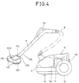
- FIG. 4 there is shown a vacuum cleaner having a universal rotary suction head of the present invention.
- the general shape of the vacuum cleaner except for the suction head remains the same as that of the typical cleaner of Fig. 1, and those elements common to both the typical cleaner and the instant cleaner will thus carry the same reference numerals.
- the reference numeral 11 denotes a dust bag which is installed in the front section of the interior of a cleaner body 10 of the vacuum cleaner in order for collecting dirts such as dust and the like.
- a suction motor unit 12 for generating a rotational force for sucking dirt-laden air into the dust bag 11 is placed in back of the dust bag 11.
- the motor unit 12 is provided with suction force means (not shown) for generating a suction force using the rotating force of the motor unit 12, which suction force will be practically used for sucking the dirt-laden air into the dust bag 11.
- suction force means Interposed between the dust bag 11 and the motor unit 12 is perforated air suction means 12a for sucking the air from the dust bag 11 and guiding the air to air exhausting means 12b.
- the air exhausting means 12b is mounted to the back of the cleaner body 10 in back of the motor unit 12 so that the air exhausting means 12b discharges the air, introduced thereto from the dust bag 11 by the suction force of the motor unit 12, to the outside of the cleaner body 10.
- Rotatably mounted to the opposed rear sides of the body 10 are a pair of larger rear wheels 13 for smooth travelling of the body 10 on a floor.
- a smaller front wheel 14 that cooperates with the rear wheels 13 for travelling of the body 10 is mounted to a front bottom of the body 10.
- a flexible hose 15 is detachably connected to the forehead of the cleaner body 10 in such a manner that the connection end of the hose 15 is connected to the front part of the dust bag 11 in the interior of the body 10.
- the other end of the flexible hose 15 is detachably connected to an end of an extension pipe 16, the other end of which extension pipe 16 is detachably connected to an end of an auxiliary pipe 700.
- the other end of the auxiliary pipe 700 is provided with an auxiliary pipe connection part 710 which is detachably connected to a top cover connection part 620 of the universal rotary suction head 1000.
- a handle 16a for handling the extension pipe 16 as well as the suction head 20 is provided in a predetermined portion of the extension pipe 16.
- the top of the universal rotary suction head 1000 is covered with a top cover 600 having the connection part 620, so that the top cover 600 protects the parts provided in the interior of the suction head from the outside impact.
- An air guide passage 610 is provided in a predetermined portion of the top cover 600 in order for guiding the sucked air laden with dirts, sucked into the interior of the suction head through a suction nozzle, to the auxiliary pipe 700.
- the bottom of the suction head 1000 is provided with brushes 110 for brushing the dirts from the floor to be cleaned before suction of the dirt-laden air and thereby improves dirt suction effect during the cleaning operation of the cleaner.
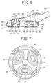
- FIG. 5 there is shown in an exploded perspective view a construction of the universal rotary suction head 1000 of the vacuum cleaner of the invention.
- a circular rotary cleaning plate 100 of a predetermined outer diameter is provided in the interior of the suction head 1000.
- the rotary cleaning plate 100 extends vertically upward to a predetermined height at its edge and is provided with a center opening having a diameter smaller than the outer diameter of the plate 100.
- the rotary cleaning plate 100 is free rotatable relative to the other parts of the suction head 1000 during the cleaning operation of the cleaner.
- the edge portion of the exterior bottom surface of the rotary cleaning plate 100 is provided with the brushes 110 which are fixed to the edge of the exterior bottom of the plate 100 such that the brushes 110 are spaced out at regular intervals.
- Fitted over the upward extending circular flange of the rotary cleaning plate 100 is an annular impact absorber 120.
- the annular impact absorber 120 is an elastic body suitable for absorbing the impact applied to the rotary cleaning plate 100 when the suction head 1000 collides on an obstacle such as a wall during cleaning operation of the cleaner, so that the impact absorber 120 protects the suction head 1000 from damage caused by the outside impact.
- the suction head 1000 also includes a stationary cleaning plate 200 which is substantially disc-shaped.
- the stationary cleaning plate 200 is received in the center opening of the rotary cleaning plate 100 and fixed to screw mounts 280a and 280b of the top cover 600 using set screws 280, which screw mounts 280a and 280b are provided on the interior surface of the top cover 600 and will be described in detail later herein.
- the center of the stationary cleaning plate 200 is provided with a predetermined diameter of circular suction nozzle 210 for sucking the air laden with dirts into the interior of the suction head 1000.
- a cylindrical boss 220 extends upward from the inside edge of the circular suction nozzle 210 of the stationary cleaning plate 200 to a predetermined height.
- the top surface of the stationary cleaning plate 200 is provided with a plurality of, for example, three, block receiving holes 230 which are spaced out at regular intervals.
- the block receiving holes 230 will receive therein a plurality of, for example, three, suspension blocks 320 of a cleaning condition control ring 300 respectively as will be described later herein.
- the top surface of the stationary cleaning plate 200 is also provided with a plurality of upward projections 240 which are spaced out at regular intervals.
- the upward projections 240 of the stationary cleaning plate 200 will be coupled to a plurality of downward projections 340 of the cleaning condition control ring 300 with interposition of compression coil springs 330 respectively as will be described later herein.
- the top edge of the stationary cleaning plate 200 includes a plurality of upward extension guiders 250 which are spaced out at regular intervals.
- the upward extension guiders 250 of the cleaning plate 200 will be coupled to predetermined portions of the bottom surface of the rotary cleaning plate 100 and guide the edge of the control ring 300.
- the bottom of the stationary cleaning plate 200 is provided with a plurality of suction slots 260 which are spaced out at regular intervals. Each suction slot 260 radially extends from the circular suction nozzle 210 to the edge of the stationary cleaning plate 200 and guides the dirt-laden air from the corner wall or the floor to the suction nozzle 210 provided in the center of the cleaning plate 200.
- the bottom of the stationary cleaning plate 200 except for the portions provided with the suction nozzle 210, the block receiving holes 230 and the suction slots 260 is provided with a great number of brushes 270.
- the brushes 270 brush the dirts such as dust from the floor to be cleaned before suction of the dirt-laden air so that the brushes 270 improve dirt suction effect of the suction head 1000 during the cleaning operation of the cleaner.
- the cleaning condition control ring 300 which is placed above the rotary cleaning plate 100 is adapted for changing cleaning conditions of the suction head 1000 in accordance with conditions of the floor to be cleaned.
- the top surface of the cleaning condition control ring 300 is provided with a plurality of triangular first selection protrusions 310 which are spaced out at regular intervals or at 120° intervals.
- the first selection protrusions 310 extend upward from the top surface of the ring 300 to a predetermined height and will be brought into slidable engagement with a plurality of second selection protrusions 420 of a position control ring 400, which ring 400 will be described in detail later herein.
- the bottom surface of the cleaning condition control ring 300 is provided with the plurality of suspension blocks 320 which are spaced out at regular intervals or at 120° intervals.
- the suspension blocks 320 extend downward from the bottom surface of the ring 300 to a predetermined height and will be detachably received in the block receiving holes 230 of the stationary cleaning plate 200 respectively.
- the bottom surface of the control ring 300 is provided with the plurality of downward projections 340. The downward projections 340 extending downward from the bottom surface of the ring 300 between the suspension blocks 320 will be coupled to the upward projections 240 of the stationary cleaning plate 200 with interposition of the coil springs 330 respectively.
- the position control ring 400 placed above the control ring 300 is adapted for controlling the position of the control ring 300 relative to the rotary cleaning plate 100.
- the position control ring 400 is provided with a control lever 410 which extends upward from a predetermined portion of the top surface of the ring 40 and will be received in a lever guide hole 630 of the top cover 600 such that the lever 410 protrudes out of the top cover 600, which top cover 600 will be described in detail layer herein.
- the position control ring 400 can be turned within a predetermined range by levering the lever 410 at the outside of the top cover 600.
- the bottom surface of the position control ring 400 is provided with the plurality of triangular second selection protrusions 420 which are spaced out at regular intervals or at 120° intervals.
- Each second selection protrusion 420 extends downward from the bottom surface of the ring 400 to a predetermined height and will be brought into slidable engagement with an associated first selection protrusion 310 of the cleaning condition control ring 300 or with the top surface of the control ring 300, thus to control the position of the cleaning condition control ring 300 relative to the rotary cleaning plate 100.
- An air guide panel 500 having predetermined length and width is placed above the position control ring 400. Opposed sides of the air guide panel 500 extend upward to a predetermined height, thus to form opposed side flanges for forming air guide passage of the panel 500.
- the air guide panel 500 is adapted for guiding the dirt-laden air to the auxiliary pipe 700, which dirt-laden air has been sucked into the interior of the suction head 1000 through the suction slots 260 and the suction nozzle 210 of the stationary cleaning plate 200.
- a front end section of the air guide panel 500 includes an air guide port 510 which has the same diameter as that of the cylindrical boss 220 of the stationary cleaning plate 200.
- the bottom end of the air guide port 510 is airtightly fitted to the top end of the cylindrical boss 220 so that the port 510 introduces the dirt-laden air from the boss 220 to the air guide passage of the panel 500.
- Each side of the air guide panel 500 includes a fixing projection 520 extending outward and having a screw hole.
- the opposed fixing projections 520 of the air guide panel 500 are interiorly fixed to predetermined portions of the top cover 600 using their associated set screws 530, thus to interiorly fix the air guide panel 500 to the top cover 600.
- the opposed side flanges of the air guide panel 500 are provided in their rear end sections with their fixing slots 540, which slots 540 will be fitted to a rear edge of the top cover 600 so as to fit the panel 500 to the top cover 600 as will be described in detail later herein.
- the top cover 600 is placed above the air guide panel 500.
- the stationary cleaning plate 200, the cleaning condition control ring 300, the position control ring 400 and the air guide panel 500 are received in the cavity of the top cover 600.
- the top cover 600 includes the air guide passage 610 for guiding the sucked dirt-laden air, sucked into the interior of the suction head 1000 through the suction nozzle 210, to the auxiliary pipe 700.
- the air guide passage 610 has a predetermined width and extends from the center of the top cover 600 to the rear edge of the cover 600 such that the guide passage 610 has the same size as that of the air guide panel 500.
- the rear end of the air guide passage 610 forms the top cover connection part 620.
- the top cover 600 is provided with the longitudinal lever guide hole 630 of a predetermined width for movably receiving the control lever 410 of the position control ring 400 such that the lever 410 protrudes out of the top cover 600.
- the top cover 600 is fitted in the rotary cleaning plate 100 such that the rotary cleaning plate 100 can be rotated relative to the top cover 600.
- the top cover connection part 620 of the top cover 600 is detachably connected to the auxiliary pipe connection part 710 of the auxiliary pipe 700.
- the auxiliary pipe 700 is for guiding the dirt-laden air to the dust bag 11 through the extension pipe 16 and the flexible hose 15, which air has been sucked into the interior of the suction head 1000 through the suction slots 260, the suction nozzle 210 of the stationary cleaning plate 200, the air guide port 510 of the air guide panel 500 and the air guide passage 610 of the top cover 600.
- Fig. 6 is a sectional view of the universal rotary suction head 1000 of the vacuum cleaner of the invention.
- the inside surface of the impact absorber 120 fitted over the upward extending circular flange of the rotary cleaning plate 100 is spaced apart from the outside edge of the top cover 600 with a predetermined gap.
- the edge of the center opening of the rotary cleaning plate 100 is spaced apart from the outside edge of the stationary cleaning plate 200. Therefore, the rotary cleaning plate 100 can be free rotated relative to the other parts of the suction head 1000.
- the front section of the stationary cleaning plate 200 is fixed to the screw mount 280a of the top cover 600 using the set screw 280, which screw mount 280a extends downward from a predetermined front portion of the interior surface of the top cover 600.
- the rear section of the stationary cleaning plate 200 is fixed to the screw mount 280b of the top cover 600 using the set screw 280, which screw mount 280b extends downward from a predetermined rear portion of the interior surface of the top cover 600.
- the suspension blocks 320 of the cleaning condition control ring 300 vertically reciprocate in the interior of their associated block receiving holes 230 of the stationary cleaning plate 200.
- Each second selection protrusion 420 of the position control ring 400 is brought into slidable engagement with an associated first selection protrusion 310 of the cleaning condition control ring 300 or with the top surface of the control ring 300.
- the position control ring 400 is placed in the interior of the suction head 1000 such that the ring 400 can be rotatable at a predetermined angle in a cavity defined between screw mount 280a of the top cover 600 and the air guide panel 500.
- Fig. 7 is a bottom view of the universal rotary suction head 1000 of the vacuum cleaner of the invention.
- the edge of the suction head 1000 is surrounded by the elastic impact absorber 120, which impact absorber 120 absorbs the impact applied to the rotary suction head 1000 when the suction head 1000 collides on an obstacle such as a wall during the cleaning operation of the cleaner, so that the impact absorber 120 protects damage of the suction head 1000 caused by the outside impact.
- the bottom of the rotary cleaning plate 100 is provided with the brushes 110, which cleaning plate 100 also rotatably receives the stationary cleaning plate 200 in its center opening. Furthermore, the bottom of the stationary cleaning plate 200 is provided with the block receiving holes 230.
- the stationary cleaning plate 200 is also provided with the plurality of suction slots 260 which are spaced out at regular intervals.
- Each suction slot 260 radially extends from the suction nozzle 210 to the edge of the stationary cleaning plate 200 and guides the dirt-laden air from the corner wall or the floor to the suction nozzle 210 provided in the center of the cleaning plate 200.
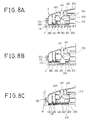
- Fig. 8A is a sectional view of the universal rotary suction head 1000 of the invention, showing the operational effect of the suction head 1000 when used for cleaning a hard floor, that is, a paper-covered floor or a wood floor.
- the cleaning condition control ring 300 is elastically biased upward by the compression coil springs 330 held by the upward projections 240 of the stationary cleaning plate 200 at their bottom ends and held by the downward projections 340 of the control ring 300 at their top ends.
- the ring 300 is elastically biased upward by the compression coil springs 330, the bottom ends of the suspension blocks 320 of the ring 300 are depressed above the brushes 270, which brushes 270 are provided on the bottom of the stationary cleaning plate 200. That is, the suspension blocks 320 do not come into contact with the hard floor to be cleaned.
- the dirts such as dust on the floor are sucked into the dust bag 11 of the cleaner body 10 along with air through the suction slots 260 and the suction nozzle 210 of the stationary cleaning plate 200, the air guide port 510 of the air guide panel 500 and the auxiliary pipe 700.
- the brushes 110 of the rotary cleaning plate 100 are rotated about the center of the plate 100 as a result of rotation of the plate 100, while the brushes 270 of the stationary cleaning plate 200 are not rotated as the stationary cleaning plate 200 is fixed.
- the brushes 270 of the stationary cleaning plate 200 previously brush the floor to be cleaned during the cleaning operation of the cleaner, thus to improve the suction effect of the suction head 1000 and achieve effective cleaning operation of the cleaner.
- the alphabet F denotes the hard floor.
- Fig. 8B is a sectional view of the universal rotary suction head 1000 of the invention, showing the operational effect of the suction head when used for cleaning a soft-carpeted floor.
- the movability of the suction head may be reduced as the brushes 110 and 270 of the suction head are apt to be dragged in the warps of the carpet of the floor and scarcely moved on the soft-carpeted floor. Therefore, the cleaning effect of the cleaner may be reduced when used for cleaning such a soft-carpeted floor.
- the universal rotary suction head 1000 of the invention can overcome the above problem so that the suction head 1000 achieves good cleaning effect even when used for cleaning of such a soft-carpeted floor.
- the cleaning condition control ring 300 is normally elastically biased upward by the compression coil springs 330 so that the bottom ends of the suspension blocks 320 of the ring 300 are depressed above the brushes 270 of the stationary cleaning plate 200 as described for the suction head 1000 in cleaning of a hard floor. That is, the suspension blocks 320 do not come into contact with the hard floor to be cleaned.
- the position of the cleaning condition control ring 300 should be controlled or lowered by handling the control lever 410 of the position control ring 400.
- the user manually turns the control lever 410 at a predetermined angle clockwise or counterclockwise at the outside of the top cover 600, so that the cleaning condition control ring 300 is pushed down by the interaction between the first and second selection protrusions 310 and 420.
- the position control ring 400 is turned by the turning motion of control lever 410, the one side surface of each triangular second protrusion 420 of the position control ring 400 slidably moves on an associated side surface of each triangular first protrusion 310 of the condition control ring 300, thus to push down the condition control ring 300.
- each second protrusion 420 will be placed on the ridge of an associated first protrusion 310 so that the bottom ends of the suspension blocks 320 of the ring 300 will project out of the brushes 110 and 270. That is, the suspension blocks 320 come into contact with the carpeted floor, while the brushes 110 and 270 are suspended above the carpeted floor as shown in Fig. 8B.
- the suction head 1000 can be more smoothly moved on the carpeted floor as the brushes 110 and 270 are spaced apart from the carpeted floor and not dragged in the warps of the carpet.
- the alphabet C denotes the carpeted floor.
- the collision impact is not directly applied to the suction head 1000 but mostly absorbed by the impact absorber 120 of the rotary cleaning plate 100, which impact absorber 120 rolls on the corner wall.
- the impact absorber 120 of the rotary cleaning plate 100 has an elasticity and rolls on the corner wall when the suction head 1000 is used about a corner so that the impact absorber 120 prevents damage of the suction head 1000 even when the suction head collides on the corner wall.
- the alphabet W denotes the corner wall.
- the above universal rotary suction nozzle of the invention can be universally used for cleaning a hard floor and a soft carpeted floor as well as for cleaning a floor partially hard and partially carpeted. That is, when cleaning a hard floor, the normal state of the suction head is kept so that the suspension blocks 320 of the cleaning condition control ring 300 are hidden in the interior of the suction head. However, when cleaning a carpeted floor, the control ring 300 is pushed down by handling the control lever 410 at the outside of the suction head so that the suspension blocks 320 of the ring 300 project out of the brushes 110 and 270 of the bottom of the suction head so as to separate the brushes 110 and 270 from the carpeted floor and to let more smooth movement of the suction head on the carpeted floor. Therefore, the suction head 1000 of the invention achieves desired cleaning effect of the cleaner regardless of conditions of a floor to be cleaned.
- the outside edge of the suction head is provided with the elastic impact absorber 120 so that the absorber 120 rolls on an obstacle such as a corner wall when the suction head is used about a corner, so that the impact absorber 120 prevents damage such as scratching of the suction head even when the suction head collides on the corner wall. Therefore, the suction nozzle of the invention keeps its clean outer appearance for a long time irrespective of repeated collisions on obstacles during cleaning operations of the cleaner.
Landscapes
- Engineering & Computer Science (AREA)
- Mechanical Engineering (AREA)
- Nozzles For Electric Vacuum Cleaners (AREA)
Applications Claiming Priority (2)
| Application Number | Priority Date | Filing Date | Title |
|---|---|---|---|
| KR1019940010102A KR960008835B1 (ko) | 1994-05-09 | 1994-05-09 | 진공청소기의 회전형 상용 흡입구 |
| KR1010294 | 1994-05-09 |
Publications (2)
| Publication Number | Publication Date |
|---|---|
| EP0681807A2 true EP0681807A2 (de) | 1995-11-15 |
| EP0681807A3 EP0681807A3 (de) | 1996-08-07 |
Family
ID=19382717
Family Applications (1)
| Application Number | Title | Priority Date | Filing Date |
|---|---|---|---|
| EP94120807A Withdrawn EP0681807A3 (de) | 1994-05-09 | 1994-12-28 | Drehbare Saugdüse eines Staubsaugers. |
Country Status (5)
| Country | Link |
|---|---|
| EP (1) | EP0681807A3 (de) |
| JP (1) | JP2644691B2 (de) |
| KR (1) | KR960008835B1 (de) |
| CN (1) | CN1121797A (de) |
| TW (1) | TW262378B (de) |
Cited By (2)
| Publication number | Priority date | Publication date | Assignee | Title |
|---|---|---|---|---|
| ES2228191A1 (es) * | 2000-10-31 | 2005-04-01 | Samsung Kwangju Electronics Co., Ltd. | Conjunto de boca de aspiracion de un aspirador. |
| US12256876B2 (en) | 2015-06-25 | 2025-03-25 | Irobot Corporation | Evacuation station |
Families Citing this family (13)
| Publication number | Priority date | Publication date | Assignee | Title |
|---|---|---|---|---|
| DE102009039507B4 (de) * | 2009-08-31 | 2012-01-26 | Fujitsu Technology Solutions Intellectual Property Gmbh | Gehäuse für ein elektronisches Gerät, elektronisches Gerät sowie Anordnung eines Einschubrahmens mit darin eingeschobenen elektronischen Einschubgeräten |
| JP5538508B2 (ja) * | 2011-10-31 | 2014-07-02 | 東京ファブリック工業株式会社 | 塗膜延命用スチーム洗浄機 |
| KR101461985B1 (ko) * | 2013-04-04 | 2014-11-14 | 엘지전자 주식회사 | 청소기 |
| EP3047771B1 (de) | 2015-01-20 | 2017-03-15 | Eurofilters Holding N.V. | Staubsaugerroboter |
| EP3047781B1 (de) | 2015-01-20 | 2019-08-28 | Eurofilters N.V. | Autonom betreibbarer Bodenstaubsauger, Verfahren zum Staubsaugen sowie Verwendung eines autonom betreibbaren Bodenstaubsaugers |
| DK3047772T3 (en) | 2015-01-20 | 2017-03-27 | Eurofilters Holding Nv | Vacuum Cleaner Robot |
| ES2640394T3 (es) * | 2015-01-20 | 2017-11-02 | Eurofilters Holding N.V. | Robot aspirador |
| CN104997466A (zh) * | 2015-07-17 | 2015-10-28 | 苏州金威特工具有限公司 | 一种低噪音的吸尘器 |
| CN104997465A (zh) * | 2015-07-17 | 2015-10-28 | 苏州金威特工具有限公司 | 一种低噪音吸尘器 |
| CN104983360A (zh) * | 2015-07-17 | 2015-10-21 | 苏州金威特工具有限公司 | 吸尘器 |
| CN106108781B (zh) * | 2016-08-18 | 2018-05-01 | 苏州市春菊电器有限公司 | 吸尘器的电机部与主机的连接结构 |
| CN107854044A (zh) * | 2017-11-14 | 2018-03-30 | 江苏经贸职业技术学院 | 一种除尘装置 |
| CN112773277A (zh) * | 2019-11-07 | 2021-05-11 | 深圳市优品家居科技有限公司 | 具有高效集成复合功能的清洁工具、清洁方法和清洁一体机 |
Family Cites Families (3)
| Publication number | Priority date | Publication date | Assignee | Title |
|---|---|---|---|---|
| US3813726A (en) * | 1972-08-04 | 1974-06-04 | Cons Foods Corp | Vacuum cleaner suction tool with pile agitator rotatable in a horizontal plane for cleaning deep pile shag rugs |
| DK239384A (da) * | 1984-05-15 | 1985-11-16 | Georg Vilhelm Petersen | Stoevsugermundstykke |
| US4589161A (en) * | 1984-08-10 | 1986-05-20 | The Scott & Fetzer Company | Vacuum driven tool |
-
1994
- 1994-05-09 KR KR1019940010102A patent/KR960008835B1/ko not_active Expired - Fee Related
- 1994-12-28 EP EP94120807A patent/EP0681807A3/de not_active Withdrawn
- 1994-12-28 TW TW083112246A patent/TW262378B/zh active
-
1995
- 1995-01-13 JP JP7003925A patent/JP2644691B2/ja not_active Expired - Fee Related
- 1995-02-10 CN CN95101924A patent/CN1121797A/zh active Pending
Cited By (3)
| Publication number | Priority date | Publication date | Assignee | Title |
|---|---|---|---|---|
| ES2228191A1 (es) * | 2000-10-31 | 2005-04-01 | Samsung Kwangju Electronics Co., Ltd. | Conjunto de boca de aspiracion de un aspirador. |
| ES2228191B2 (es) * | 2000-10-31 | 2006-07-16 | Samsung Kwangju Electronics Co., Ltd. | Conjunto de boca de aspiracion de un aspirador. |
| US12256876B2 (en) | 2015-06-25 | 2025-03-25 | Irobot Corporation | Evacuation station |
Also Published As
| Publication number | Publication date |
|---|---|
| KR960008835B1 (ko) | 1996-07-05 |
| KR950030965A (ko) | 1995-12-18 |
| CN1121797A (zh) | 1996-05-08 |
| EP0681807A3 (de) | 1996-08-07 |
| TW262378B (de) | 1995-11-11 |
| JP2644691B2 (ja) | 1997-08-25 |
| JPH07299015A (ja) | 1995-11-14 |
Similar Documents
| Publication | Publication Date | Title |
|---|---|---|
| EP0681807A2 (de) | Drehbare Saugdüse eines Staubsaugers | |
| EP0635236B1 (de) | Elektrisches Gerät zur Saugreinigung von Oberflächen | |
| EP1415583B1 (de) | Bodensauggerät für Staubsauger | |
| CN1028599C (zh) | 真空吸尘器 | |
| US7150069B2 (en) | Electric vacuum cleaner | |
| JP3424151B2 (ja) | 電気掃除機の床ノズル | |
| EP1190660A2 (de) | Vielseitiger Staubsauger | |
| US20090089967A1 (en) | Suction nozzle for use in vacuum cleaner | |
| CA2329018C (en) | Brush and spacer assembly | |
| US20060042041A1 (en) | Vacuum cleaner and suction nozzle structure thereof | |
| US5131114A (en) | Vacuum cleaner | |
| KR100302432B1 (ko) | 전기 청소기의 흡입구 부재 | |
| JP3366539B2 (ja) | 小型電気掃除機 | |
| KR100783155B1 (ko) | 로봇청소기 | |
| US6685233B2 (en) | Suction hose assembly for an upright type vacuum cleaner | |
| JP4190318B2 (ja) | 自走式掃除機 | |
| KR101724153B1 (ko) | 걸레청소용 로봇청소기 | |
| JP2010273991A (ja) | 吸込口体および電気掃除機 | |
| JPH0517013Y2 (de) | ||
| JP3199373B2 (ja) | 電気掃除機の床用吸込具 | |
| KR100207235B1 (ko) | 진공청소기의 가변형 브러쉬 머리부 | |
| CN120267175A (zh) | 清洁设备 | |
| EP4062815B1 (de) | Multifunktionale staubsaugerdüse | |
| JPS6038443Y2 (ja) | 電気掃除機 | |
| JP3246451B2 (ja) | 電気掃除機 |
Legal Events
| Date | Code | Title | Description |
|---|---|---|---|
| PUAI | Public reference made under article 153(3) epc to a published international application that has entered the european phase |
Free format text: ORIGINAL CODE: 0009012 |
|
| AK | Designated contracting states |
Kind code of ref document: A2 Designated state(s): BE CH DE LI SE |
|
| PUAL | Search report despatched |
Free format text: ORIGINAL CODE: 0009013 |
|
| AK | Designated contracting states |
Kind code of ref document: A3 Designated state(s): BE CH DE LI SE |
|
| 17P | Request for examination filed |
Effective date: 19970109 |
|
| 17Q | First examination report despatched |
Effective date: 19980116 |
|
| STAA | Information on the status of an ep patent application or granted ep patent |
Free format text: STATUS: THE APPLICATION HAS BEEN WITHDRAWN |
|
| 18W | Application withdrawn |
Withdrawal date: 19980313 |