EP0681908A1 - Device for compacting and/or transporting waste wrapping film - Google Patents
Device for compacting and/or transporting waste wrapping film Download PDFInfo
- Publication number
- EP0681908A1 EP0681908A1 EP95106633A EP95106633A EP0681908A1 EP 0681908 A1 EP0681908 A1 EP 0681908A1 EP 95106633 A EP95106633 A EP 95106633A EP 95106633 A EP95106633 A EP 95106633A EP 0681908 A1 EP0681908 A1 EP 0681908A1
- Authority
- EP
- European Patent Office
- Prior art keywords
- press plate
- container
- side walls
- packaging material
- press
- Prior art date
- Legal status (The legal status is an assumption and is not a legal conclusion. Google has not performed a legal analysis and makes no representation as to the accuracy of the status listed.)
- Withdrawn
Links
- 239000002699 waste material Substances 0.000 title 1
- 238000007906 compression Methods 0.000 claims abstract description 9
- 230000006835 compression Effects 0.000 claims abstract description 8
- 239000000463 material Substances 0.000 claims abstract description 6
- 239000005022 packaging material Substances 0.000 claims abstract 6
- 238000004806 packaging method and process Methods 0.000 claims description 5
- 239000002985 plastic film Substances 0.000 claims 1
- 229920006255 plastic film Polymers 0.000 claims 1
- 238000010276 construction Methods 0.000 description 2
- 229920000742 Cotton Polymers 0.000 description 1
- 239000011888 foil Substances 0.000 description 1
- 239000004615 ingredient Substances 0.000 description 1
- 238000003780 insertion Methods 0.000 description 1
- 230000037431 insertion Effects 0.000 description 1
- 239000002184 metal Substances 0.000 description 1
- 229920006280 packaging film Polymers 0.000 description 1
- 239000012785 packaging film Substances 0.000 description 1
- 238000004064 recycling Methods 0.000 description 1
- 239000000725 suspension Substances 0.000 description 1
- 230000008961 swelling Effects 0.000 description 1
Images

Classifications
-
- B—PERFORMING OPERATIONS; TRANSPORTING
- B30—PRESSES
- B30B—PRESSES IN GENERAL
- B30B9/00—Presses specially adapted for particular purposes
- B30B9/30—Presses specially adapted for particular purposes for baling; Compression boxes therefor
- B30B9/3003—Details
- B30B9/3032—Press boxes
-
- B—PERFORMING OPERATIONS; TRANSPORTING
- B30—PRESSES
- B30B—PRESSES IN GENERAL
- B30B9/00—Presses specially adapted for particular purposes
- B30B9/30—Presses specially adapted for particular purposes for baling; Compression boxes therefor
- B30B9/3003—Details
-
- B—PERFORMING OPERATIONS; TRANSPORTING
- B30—PRESSES
- B30B—PRESSES IN GENERAL
- B30B9/00—Presses specially adapted for particular purposes
- B30B9/30—Presses specially adapted for particular purposes for baling; Compression boxes therefor
- B30B9/3003—Details
- B30B9/3014—Ejection means
-
- B—PERFORMING OPERATIONS; TRANSPORTING
- B30—PRESSES
- B30B—PRESSES IN GENERAL
- B30B9/00—Presses specially adapted for particular purposes
- B30B9/30—Presses specially adapted for particular purposes for baling; Compression boxes therefor
- B30B9/305—Drive arrangements for the press ram
- B30B9/3053—Hand- or foot-operated presses
-
- B—PERFORMING OPERATIONS; TRANSPORTING
- B30—PRESSES
- B30B—PRESSES IN GENERAL
- B30B9/00—Presses specially adapted for particular purposes
- B30B9/30—Presses specially adapted for particular purposes for baling; Compression boxes therefor
- B30B9/3082—Presses specially adapted for particular purposes for baling; Compression boxes therefor with compression means other than rams performing a rectilinear movement
-
- B—PERFORMING OPERATIONS; TRANSPORTING
- B65—CONVEYING; PACKING; STORING; HANDLING THIN OR FILAMENTARY MATERIAL
- B65F—GATHERING OR REMOVAL OF DOMESTIC OR LIKE REFUSE
- B65F1/00—Refuse receptacles; Accessories therefor
- B65F1/14—Other constructional features; Accessories
- B65F1/1405—Compressing means incorporated in, or specially adapted for, refuse receptacles
-
- B—PERFORMING OPERATIONS; TRANSPORTING
- B65—CONVEYING; PACKING; STORING; HANDLING THIN OR FILAMENTARY MATERIAL
- B65F—GATHERING OR REMOVAL OF DOMESTIC OR LIKE REFUSE
- B65F1/00—Refuse receptacles; Accessories therefor
- B65F1/14—Other constructional features; Accessories
- B65F1/1426—Housings, cabinets or enclosures for refuse receptacles
Definitions
- the invention relates to a device for compacting and / or transporting materials resulting from the packaging of the type specified in the preamble of claim 1.
- No. 3,797,382 shows that raw cotton can be compacted in superstructures on flatbed trucks a hydraulic press arranged, for example, as an additional device on a vehicle.
- films used in packaging for example in department stores, food markets and the like. The like. Incurred in large quantities by the fact that factory packaging must be removed in order to be able to stack the containers in a customer-specific manner, are pressed together in so-called film compressors.
- These compressors are usually stationary hydraulic presses that are comparatively complex to design and therefore also expensive to purchase. Such presses are known, for example, from the "Schäfershop" catalog, March 1994, page 716.
- the object of the invention is to provide a solution with which it is possible to compress films using simple means, the compression device itself being able to be used simultaneously, if desired, as a transport container for the compressed film.
- the inner surfaces of the container walls have a friction-increasing design, it is possible to compress the film in stages in the container, wherein the press plate can be designed by the guide so that it can also be operated by hand.
- a particularly simple design is to form the wall surfaces of the container from mesh and to provide the container itself with rollers if necessary.
- the press shield with a sleeve-like guide on a perforated guide tube for height adjustment.
- the sleeve for the press plate can be provided with a ratchet / catch lock, which can be unlocked using a handle, and a belt strap with a deflection roller can be provided for lifting the guide tube.
- the handling lever of the press plate can be designed to be foldable and / or telescopic u. Like. more.
- the invention provides that two adjacent side walls of the container can be swung open relative to the stationary side walls.
- drums for binding wires, binding straps or binding tapes can be provided in order to enable the pressed foil bales to be gripped or wrapped around.
- the device is designed in the example shown as a lattice box movable on rollers 2, the side walls arranged on the bottom surface labeled 3 and having the rollers 2 being provided with mesh grids 4 in corresponding metal frames.
- the device 1 has a front wall 5, a rear wall 6, a first end wall 7 and a further end wall 8, the end walls 7 and 8 being formed approximately in the middle.
- the one end wall 7 has a similar middle division as the end wall 8.
- a perforated tube 15 with a plurality of locking holes 16 is arranged, the perforated tube 15 being of a sleeve 17 is surrounded, which carries the pivot axis 13 of the handling lever 10.
- the edge regions of the side walls 5 to 8 can be equipped with drums 27 for binding wire 28 or the like, such a drum being only indicated in a simplified manner.
- the press plate 9 Due to the type of suspension of the press plate 9, it can be folded out of its top dead center position, for example, against the wall surface 7.
- the side walls 5 and 8 can be folded completely outwards or inwards, in order to enable an essentially L-shaped configuration of the device 1 as a transport position.
Landscapes
- Engineering & Computer Science (AREA)
- Mechanical Engineering (AREA)
- Auxiliary Devices For And Details Of Packaging Control (AREA)
- Basic Packing Technique (AREA)
Abstract
Description
Die Erfindung richtet sich auf eine Vorrichtung zum Verdichten und/oder Transportieren von bei der Verpackung anfallenden Materialien der im Oberbegriff des Anspruches 1 angegebenen Gattung.The invention relates to a device for compacting and / or transporting materials resulting from the packaging of the type specified in the preamble of claim 1.
Einrichtungen zum Verdichten von Materialien sind seit langem in unterschiedlichen Gestaltungen bekannt. So stellt die US-1 090 257 einen gattungsbildenden Stand der Technik dar. Vergleichbare Lösungen zeigt auch die US-2 330 165 oder die US-2 423 309. Bei diesen bekannten Lösungen wird ein Materialballen innerhalb einer aufklappbaren Umhüllung, aus Holzwänden, durch schrittweises Absenken eines Preßschildes gebildet.Devices for compacting materials have long been known in various designs. Thus, US-1 090 257 represents a generic state of the art. Comparable solutions are also shown in US-2 330 165 or US-2 423 309. In these known solutions, a material bale within a hinged envelope, made of wooden walls, is gradually removed Lowering of a press shield is formed.
Um ein Aufschwenken des Preßschildes aufgrund des sich wieder aufblähenwollenden Materiales zu verhindern, ist bei der US-1 090 257 eine Gegensperre vorgesehen, die Lösung nach der US-2 423 209 bedient sich einer den Schwenkhebel des Preßschildes in Absenkstellung haltenden Kette.In order to prevent the press plate from swiveling open due to the material which is to be inflated again, a counter-lock is provided in US Pat. No. 1,090,257; the solution according to US Pat. No. 2,423,209 uses a chain that holds the swivel lever of the press shield in the lowered position.
Um Rohbaumwolle in Aufbauten auf Pritschen-Lastkraftwagen verdichtet transportieren zu können, zeigt die US-3 797 382 eine beispielsweise als Zusatzgerät an einem Fahrzeug angeordnete hydraulische Presse.No. 3,797,382 shows that raw cotton can be compacted in superstructures on flatbed trucks a hydraulic press arranged, for example, as an additional device on a vehicle.
Um Müll in Mülltonnen dichter packen zu können sind Handhebel-Tellerpressen bekannt, deren Teller von oben in die Mülltonne eindringt. Als Beispiel seien hier genannt DE-U-75 33 707 und DE-U-81 22 240.In order to be able to pack garbage in garbage cans more densely, hand lever plate presses are known, the plates of which penetrate into the garbage can from above. Examples include DE-U-75 33 707 and DE-U-81 22 240.
Nachteilig an den bekannten Lösungen ist z.B., daß aufgrund der Konstruktion das Preßschild nach Teilpreßvorgängen nicht wieder angehoben werden kann. In der Regel werden auch der Preßeinrichtung zugeordnete Behälter nicht selbst als Transportbehälter eingesetzt, sieht man von den Mülltonnen nach den beiden deutschen Gebrauchsmustern ab, die aber nicht integraler Bestandteil der Preßeinrichtung sind.A disadvantage of the known solutions is, for example, that, due to the construction, the press plate cannot be raised again after partial pressing operations. As a rule, containers assigned to the pressing device are not themselves used as transport containers, apart from the garbage cans according to the two German utility models, which, however, are not an integral part of the pressing device.
Es ist auch bekannt, daß Folien, die bei Verpackungen z.B. bei Kaufhäusern, Lebensmittelmärkten u. dgl., in großen Mengen dadurch anfallen, daß Werkverpackungen entfernt werden müssen, um die Gebinde kundengerecht stapeln zu können, in sogenannten Folienverdichtern zusammengepreßt werden. Bei diesen Verdichtern handelt es sich in der Regel um ortsfeste hydraulische Pressen, die vergleichsweise aufwendig in der Gestaltung und damit auch teuer in der Anschaffung sind. Derartige Pressen sind beispielsweise aus dem "Schäfershop"-Katalog, März 1994, Seite 716, bekannt.It is also known that films used in packaging, for example in department stores, food markets and the like. The like. Incurred in large quantities by the fact that factory packaging must be removed in order to be able to stack the containers in a customer-specific manner, are pressed together in so-called film compressors. These compressors are usually stationary hydraulic presses that are comparatively complex to design and therefore also expensive to purchase. Such presses are known, for example, from the "Schäfershop" catalog, March 1994, page 716.
Es gibt Einsatzfälle, in denen derartig aufwendige Pressen entbehrlich sind, wobei die bekannten Pressen auch den Nachteil haben, daß in jedem Falle die verdichteten Inhaltsstoffe entnommen werden müssen, um dann weitertransportiert werden zu können.There are cases in which such complex presses can be dispensed with, the known presses also having the disadvantage that the compressed ingredients must be removed in any case in order to then be able to be transported further.
Aufgabe der Erfindung ist die Schaffung einer Lösung, mit der es möglich ist, mit einfachen Mitteln Folien zu verdichten, wobei die Verdichtungseinrichtung selbst gleichzeitig, wenn gewünscht, als Transportbehälter für die komprimierte Folie genutzt werden kann.The object of the invention is to provide a solution with which it is possible to compress films using simple means, the compression device itself being able to be used simultaneously, if desired, as a transport container for the compressed film.
Mit einer Vorrichtung der eingangs bezeichneten Art wird diese Aufgabe gemäß der Erfindung durch die kennzeichnenden Merkmale des Anspruches 1 gelöst.With a device of the type described in the introduction, this object is achieved according to the invention by the characterizing features of claim 1.
Dadurch, daß die Innenflächen der Behälterwände eine reibungserhöhende Gestaltung aufweisen, ist es möglich, im Behälter die Folie etappenweise zu verdichten, wobei das Preßschild durch die Führung so gestaltet werden kann, daß es auch von Hand betätigbar ist.Characterized in that the inner surfaces of the container walls have a friction-increasing design, it is possible to compress the film in stages in the container, wherein the press plate can be designed by the guide so that it can also be operated by hand.
Weitere vorteilhafte Ausgestaltungen der Erfindung ergeben sich aus den Unteransprüchen.Further advantageous embodiments of the invention result from the subclaims.
Eine besonders einfache Gestaltung liegt darin, die Wandflächen des Behälters aus Maschengittern zu bilden und den Behälter selbst ggf. mit Laufrollen zu versehen.A particularly simple design is to form the wall surfaces of the container from mesh and to provide the container itself with rollers if necessary.
Eine solche Gitterkonstruktion mit Laufrollen ist leicht, damit einfach zu transportieren und stellt somit eine besonders zweckmäßige Gestaltung der Erfindung für den Fall dar, daß die Gesamtvorrichtung auch als Transportvorrichtung herangezogen werden soll.Such a lattice construction with rollers is light, so that it is easy to transport and thus represents a particularly expedient embodiment of the invention in the event that the overall device is also to be used as a transport device.
Beim Verdichten wird die Folie durch die Freiräume des Maschengitters nach außen gedrückt und verklemmt sich damit an den Seitenwänden in einer solchen Weise, daß nach einem Verdichtungsvorgang das Preßschild wieder in die obere Totpunktlage zurückgehoben werden kann, ohne daß die verdichtete Folie nennenswert aufquillt oder zurückfedert.When compressing the film is pressed out through the free spaces of the mesh and jammed on the side walls in such a way that after a compression process, the press plate can be raised back to the top dead center position without the compacted film swelling or springing back significantly.
Dabei ist es besonders zweckmäßig, das Preßschild mit einer hülsenartigen Führung an einem gelochten Führungsrohr zur Höhenverstellung zu versehen. Die Hülse für das Preßschild kann mit einer Klinken-/Rastsperre versehen sein, die über einen Handhabungsgriff entriegelbar ist, wobei zum Anheben des Führungsrohres ein Gurtband mit Umlenkrolle vorgesehen sein kann.It is particularly expedient to provide the press shield with a sleeve-like guide on a perforated guide tube for height adjustment. The sleeve for the press plate can be provided with a ratchet / catch lock, which can be unlocked using a handle, and a belt strap with a deflection roller can be provided for lifting the guide tube.
Um in der Transportlage nicht zu stören, kann der Handhabungshebel des Preßschildes klappbar und/oder teleskopierbar ausgebildet sein u. dgl. mehr.In order not to interfere in the transport position, the handling lever of the press plate can be designed to be foldable and / or telescopic u. Like. more.
Um ein einfaches Entnehmen des Folienballens zu gewährleisten sieht die Erfindung vor, daß zwei benachbarte Seitenwände des Behälters gegenüber ortsfesten Seitenwänden aufschwenkbar sind.In order to ensure easy removal of the film bale, the invention provides that two adjacent side walls of the container can be swung open relative to the stationary side walls.
Wird die Vorrichtung unmittelbar als Verpackungseinheit benutzt, um die komprimierte Folie zu einem Aufbearbeitungsbetrieb zu befördern, kann es nützlich sein, die Leervorrichtung möglichst platzsparend retournieren zu können. Hierzu sieht die Erfindung vor, daß die Seitenwandflächen zum Leertransport der Vorrichtung wenigstens L-förmig zusammenklappbar sind, derart, daß mehr entsprechend zusammengeklappte Vorrichtungen ineinander gestapelt transportierbar sind.If the device is used directly as a packaging unit in order to convey the compressed film to a processing plant, it can be useful to be able to return the empty device as space-saving as possible. For this purpose, the invention provides that the side wall surfaces for the empty transport of the device can be folded at least in an L-shape, in such a way that more correspondingly folded devices can be transported stacked one inside the other.
Auch bei der vorliegenden Erfindung können Trommeln für Bindedrähte, Bindegurte oder Bindebänder vorgesehen sein, um ein Umgreifen oder Umschlingen der gepreßten Folienballen zu ermöglichen.In the present invention, too, drums for binding wires, binding straps or binding tapes can be provided in order to enable the pressed foil bales to be gripped or wrapped around.
Die Erfindung ist nachstehend anhand der Zeichnung beispielsweise näher erläutert. Diese zeigt in
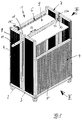
- Fig. 1
- eine vereinfachte perspektivische Darstellung der Vorrichtung im geschlossenen Zustand,
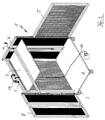
- Fig. 2
- in gleicher Darstellungsweise die Vorrichtung im geöffneten Zustand,
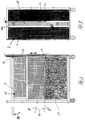
- Fig. 3
- eine Seitenansicht gemäß Pfeil III in Fig. 1,
- Fig. 4
- eine Seitenansicht gemäß Pfeil IV in Fig. 1 sowie in den
- Fig. 5 bis 7
- Einzelheiten einer möglichen Ausführungsform einer Rast-/Klinkenverbindung.
- Fig. 1
- a simplified perspective view of the device in the closed state,
- Fig. 2
- in the same representation, the device in the open state,
- Fig. 3
- 2 shows a side view according to arrow III in FIG. 1,
- Fig. 4
- a side view according to arrow IV in Fig. 1 and in the
- 5 to 7
- Details of a possible embodiment of a latch / jack connection.
Die allgemein mit 1 bezeichnete Vorrichtung ist im dargestellten Beispiel als auf Laufrollen 2 bewegbarer Gitterkasten ausgebildet, wobei die auf der mit 3 bezeichneten und die Laufrollen 2 aufweisenden Bodenfläche angeordneten Seitenwände in entsprechenden Metallrahmen mit Netzgittern 4 versehen sind.The device, generally designated 1, is designed in the example shown as a lattice box movable on
Im dargestellten Beispiel weist die Vorrichtung 1 eine Vorderwand 5, eine Rückwand 6, eine erste Stirnwand 7 und eine weitere Stirnwand 8 auf, wobei die Stirnwände 7 und 8 etwa mittig geschlitzt ausgebildet sind.In the example shown, the device 1 has a
Dem Boden 3 gegenüber ist ein mit 9 bezeichnetes Preßschild angeordnet, welches einen Handhabungshebel 10 aufweist, der durch einen mit 11 bezeichneten Schlitz in der Stirnwand 2 nach außen ragend geführt ist.Arranged opposite the
Das dem Handhabungshebel 10 abgewandte gegenüberliegende Ende ist drehgelenkig gelagert, wobei Einzelheiten der Lagerung insbesondere der Fig. 6 zu entnehmen sind. In Fig. 1 ist noch angedeutet, daß der Handhabungshebel 10 abknickbar oder teleskopierbar am Preßschild 9 angeordnet sein kann, derart, daß er in der Transportlage die Außenkontur der Vorrichtung 1 nicht überragt. Die Teleskopierbarkeit ist mit dem Doppelpfeil 12 angeordnet, die um ein Drehgelenk 13 mögliche Verschränkbarkeit des Preßschildes 9 ist mit dem Doppelpfeil 14 in Fig. 3 angedeutet.The opposite end facing away from the
Wie sich insbesondere aus Fig. 4 ergibt, weist die eine Stirnwand 7 eine ähnliche mittlere Teilung auf wie die Stirnwand 8. Im sich ergebenden Mittelschlitz 11a ist ein gelochtes Rohr 15 mit einer Vielzahl von Rastlöchern 16 angeordnet, wobei das gelochte Rohr 15 von einer Hülse 17 umgeben ist, die die Schwenkachse 13 des Handhabungshebels 10 trägt.As can be seen in particular from FIG. 4, the one
Neben dem Handhabungshebel 10 trägt die Hülse 17 auch noch einen Rastenhebel, allgemein mit 18 bezeichnet, der einen Rastnocken 19 aufweist, der in die Löcher 16 des gelochten Rohres 15 eingreifen kann. Zum Entsperren kann ein Griff 20 vorgesehen sein. Um ein völliges Aufschwenken zu verhindern, ist die Hülse 17 noch mit einem Endanschlag 21 ausgerüstet.In addition to the handling
In den Figuren ist noch angedeutet, daß im Bereich der Schwenkachse 13 bzw. der Hülse 17 ein Gurtband 22 mit einer Klemme 23 vorgesehen sein kann. Mit diesem Gurtband kann das Preßschild 9 angehoben werden.In the figures it is also indicated that a
Die Wirkungsweise der Vorrichtung ist dabei die folgende:
In der in Fig. 1 bzw. Fig. 3 dargestellten oberen Totpunktlage des von einem ausschwenkbaren Stift 25 gehaltenen Preßschild 9 kann die Vorrichtung 1 mit Folie 24 gefüllt werden, da die in Fig. 1 vordere Behälterwand 5 eine geringere Höhe als die anderen Seitenwände aufweist, um so einen Einwurfschlitz für die Folie bereitzustellen. Wenn das sich ergebende Volumen der Vorrichtung 1 mit Folie gefüllt ist, kann der Sperriegel 25 weggeschwenkt werden, nachdem beispielsweise vorher die Sperre 23 des Haltegurtes 22 gelöst wurde, so daß dann das Preßschild 9 nach unten fällt etwa in die mit 9' bezeichnete gestrichelte Position in Fig. 3.The operation of the device is as follows:
In the top dead center position shown in FIG. 1 or FIG. 3 of the
Dadurch ergibt sich allein auch durch das Gewicht des Preßschildes 9 eine gewisse Verdichtung der Folie.This results in a certain compression of the film solely by the weight of the
Wird nun der Handhabungshebel gemäß Pfeil 14 nach unten geschwenkt, ergibt sich dadurch eine weitere Verdichtung der Folie 24. Die Rastsperre 18 sperrt dabei einseitig den Handhabungshebel 10 in der Weise, daß der Klinkennocken 19 in eine in der Nähe befindliche Öffnung 16 im Rohr 15 eingreift, die Hülse 17 sperrt und damit eine Verschwenkung des Preßschildes 9 um die Achse 13 möglich macht. Durch das Zusammenpressen werden Folienbereiche in die Lücken der Gitterflächen 14 eingedrückt. Wird nun das Preßschild 9 aus der Position 9'' wieder in die obere Totpunktlage durch Anheben verbracht, kommt es zu keinem wesentlichen Aufblähen der komprimierten Folie 24, da sich diese in der reibungserhöhenden Gestaltung der Wandflächen der Vorrichtung 1 verklemmt.If the handling lever is now pivoted downwards according to
Zum Anheben des Preßschildes 9 wird der Handhabungsgriff 20 betätigt und gemäß Pfeil 26 bei Fig. 6 nach oben geschwenkt, derart, daß die Rastsperre 19 außer Eingriff gerät, die Rastsperre 18 legt sich dann an den Anschlag 21, derart, daß die Hülse 17 nach oben gehoben werden kann. Dies kann ggf. durch automatische Anbindung des Gurtes 22 durch dessen Betätigung erfolgen.To lift the
Ist die Vorrichtung 1 mit komprimierter Folie gefüllt, kann sie insgesamt zur Weiterverarbeitung der Verpackungsfolie zu einem entsprechenden Recycle-Betrieb verbracht werden, der entstandene Folienballen kann aber auch entnommen werden, wozu es möglich ist (wie sich dies insbesondere aus Fig. 2 ergibt) zwei benachbarte Seitenwände, im dargestellten Beispiel die Seitenwände 5 und 8, aufzuschwenken, während die benachbarten Seitenwände 6 und 7 einschließlich der Bodenplatte 3 fest miteinander verbunden bleiben.If the device 1 is filled with compressed film, it can be taken to a corresponding recycling operation for further processing of the packaging film, but the resulting film bale can also be removed, for which it is possible (as can be seen in particular from FIG. 2) two Adjacent side walls, in the example shown, the
Die Randbereiche der Seitenwände 5 bis 8 können mit Trommeln 27 für Bindedraht 28 od. dgl. ausgerüstet sein, wobei eine solche Trommel lediglich vereinfacht wiedergegeben angedeutet ist.The edge regions of the
Durch die Art der Aufhängung des Preßschildes 9 kann dieses aus seiner oberen Totpunktlage beispielsweise gegen die Wandfläche 7 geklappt werden. Je nach Abmessung können die Seitenwände 5 und 8 vollständig nach außen oder nach innen umgelegt werden, um so eine im wesentlichen L-förmige Konfiguration der Vorrichtung 1 als Transportposition zu ermöglichen. Grundsätzlich ist es auch möglich, sämtliche Seiten- und Bodenwände miteinander in Scharnierverbindung zu bringen, um ein gänzliches Zusammenfalten zu ermöglichen.Due to the type of suspension of the
Im übrigen ist das beschriebene Ausführungsbeispiel der Erfindung noch in vielfacher Hinsicht abzuändern, ohne den Grundgedanken zu verlassen. So kann die Rastsperre 18 auch als eine Rutschkupplung ohne Rohr mit Lochbohrungen ausgebildet sein. Wie in den Figuren angedeutet, könnte statt des gelochten Rohres auch ein Gewinderohr mit Gewindespindel vorgesehen sein, um z.B. durch etwa einen kleinen Handkurbeltrieb 26 (Fig. 2) die eine Anlenkungsposition des Preßschildes auf- und abzusenken.Otherwise, the described embodiment of the invention can be modified in many ways without departing from the basic idea. The
Claims (10)
dadurch gekennzeichnet,
daß insbesondere zum Verpressen von Kunststoffolien als Verpackungsmaterial die Innenflächen der Behälterwände (5-8) eine derartig reibungserhöhende Gestaltung aufweisen, daß das Preßschild (9) nach einem Verdichtungsschritt in eine den dabei gebildeten Folienballen freigebende, ein weiteres Befüllen oder ein Entnehmen ermöglichende Stellung anhebbar ist.Device (1) for compacting and / or transporting materials resulting from packaging with a receptacle for the packaging material and a press plate (9) for compressing the packaging material, the press plate (9) being guided from or between two opposite container walls and with a the pressing position (10) facing outwards is equipped,
characterized,
that, in particular for pressing plastic films as packaging material, the inner surfaces of the container walls (5-8) have such a friction-increasing design that the press plate (9) can be raised after a compression step into a position that releases the resulting film bale, enables further filling or removal .
dadurch gekennzeichnet,
daß die Wandflächen (5-8) des Aufnahmehälters von Maschengittern (4) gebildet sind.Device according to claim 1,
characterized,
that the wall surfaces (5-8) of the receptacle are formed by mesh (4).
dadurch gekennzeichnet,
daß das Preßschild (9) an einer etwa mittig angeordneten Hülse (17), die ein gelochtes Führungsrohr (15) umgreift, schwenkbar geführt ist, wobei der Hülse (17) für das Preßschild (9) eine Rastsperre (18), insbesondere eine Klinke mit einem Eingriffsnocken (19), zum Eingriff in ein Loch (16) des Führungsrohres (15) zugeordnet ist.Device according to claim 1 or 2,
characterized,
that the press plate (9) is pivotably guided on an approximately centrally arranged sleeve (17) which surrounds a perforated guide tube (15), the sleeve (17) for the press plate (9) having a detent (18), in particular a pawl with an engagement cam (19) for engagement in a hole (16) of the guide tube (15).
dadurch gekennzeichnet,
daß an der Rastsperre (18) ein Griff (20) od. dgl. zur Aufhebung der Rastsperre vorgesehen ist und/oder daß der Handhabungshebel (10) am Preßschild (9) wegschwenkbar und/oder teleskopierbar angeordnet ist.Device according to one of the preceding claims,
characterized,
that a handle (20) or the like is provided on the detent lock (18) for lifting the detent lock and / or that the handling lever (10) on the press plate (9) can be pivoted away and / or is arranged telescopically.
dadurch gekennzeichnet,
daß im Bereich des Führungsrohres (15) ein Gurtband (22) mit oberer Umlenkrolle (22a) vorgesehen ist zum Anheben des Preßschildes (9) in die obere Totpunktlage.Device according to one of the preceding claims,
characterized,
that in the area of the guide tube (15) a webbing (22) with an upper deflection roller (22a) is provided for lifting the press shield (9) into the top dead center position.
dadurch gekennzeichnet,
daß zwei benachbarte Seitenwände (6,7) des Behälters ortsfest an der Bodenplatte (3) und die beiden anderen Seitenwände (5,8) aufschwenkbar angeordnet sind.Device according to one of the preceding claims,
characterized,
that two adjacent side walls (6, 7) of the container are fixed in place on the base plate (3) and the other two side walls (5, 8) are arranged so that they can be swung open.
dadurch gekennzeichnet,
daß die Seitenwandflächen (5-8) zum Leertransport der Vorrichtung (1) wenigstens L-förmig zusammenklappbar sind.Device according to one of the preceding claims,
characterized,
that the side wall surfaces (5-8) for the empty transport of the device (1) can be folded at least in an L-shape.
dadurch gekennzeichnet,
daß die Höhe wenigstens einer nicht zur Führung des Preßschildes (9) herangezogenen Seitenwand (5) geringer ist als die Höhe der benachbarten Seitenwände (7,8).Device according to one of the preceding claims,
characterized,
that the height of at least one side wall (5) not used for guiding the press plate (9) is less than the height of the adjacent side walls (7, 8).
dadurch gekennzeichnet,
daß die Bodenplatte mit Laufrollen ausgerüstet ist.Device according to one of the preceding claims,
characterized,
that the base plate is equipped with rollers.
dadurch gekennzeichnet,
daß Trommeln (27) für Bindedraht (28), Bindegurte oder Bindebänder mindestens in einem Stirnseitenbereich einer Wandfläche vorgesehen sind.Device according to one of the preceding claims,
characterized,
that drums (27) for binding wire (28), binding straps or binding tapes are provided at least in an end region of a wall surface.
Applications Claiming Priority (2)
| Application Number | Priority Date | Filing Date | Title |
|---|---|---|---|
| DE4417061 | 1994-05-14 | ||
| DE19944417061 DE4417061A1 (en) | 1994-05-14 | 1994-05-14 | Device for compacting and / or transporting films produced in packaging |
Publications (1)
| Publication Number | Publication Date |
|---|---|
| EP0681908A1 true EP0681908A1 (en) | 1995-11-15 |
Family
ID=6518163
Family Applications (1)
| Application Number | Title | Priority Date | Filing Date |
|---|---|---|---|
| EP95106633A Withdrawn EP0681908A1 (en) | 1994-05-14 | 1995-05-03 | Device for compacting and/or transporting waste wrapping film |
Country Status (2)
| Country | Link |
|---|---|
| EP (1) | EP0681908A1 (en) |
| DE (2) | DE4417061A1 (en) |
Cited By (3)
| Publication number | Priority date | Publication date | Assignee | Title |
|---|---|---|---|---|
| WO2007011250A1 (en) * | 2005-07-19 | 2007-01-25 | Nela Ene | Compacting press for recycling supple and semi-rigid materials |
| CN100526063C (en) * | 2006-05-29 | 2009-08-12 | 邵远金 | Manual pressure biological straw compacting machine |
| WO2019077378A1 (en) * | 2017-10-20 | 2019-04-25 | J.C. Dyke Supplies Limited | Container with compression device |
Families Citing this family (2)
| Publication number | Priority date | Publication date | Assignee | Title |
|---|---|---|---|---|
| DE29514762U1 (en) * | 1995-09-14 | 1995-11-23 | Meister, Karlhans, 72293 Glatten | Containers for collecting and pressing recyclable raw materials and waste |
| FR2910371A1 (en) * | 2006-12-20 | 2008-06-27 | Nela Ene | Compacting press for recycling supple semi-rigid materials, has knobs in command board for controlling compacting plate, to press waste in storing container positioned between columns |
Citations (7)
| Publication number | Priority date | Publication date | Assignee | Title |
|---|---|---|---|---|
| US1090257A (en) * | 1913-05-12 | 1914-03-17 | Monarch Mfg Company | Baling apparatus. |
| US2330165A (en) * | 1942-02-18 | 1943-09-21 | Thomas E Wykes | Paper baler |
| US2423209A (en) * | 1944-05-20 | 1947-07-01 | Daniel H Storey | Paper baler |
| US3757682A (en) * | 1971-07-14 | 1973-09-11 | Automatic Refuse System Inc | Dolly-mounted bag holder for refuse compactor |
| US3797382A (en) * | 1972-02-25 | 1974-03-19 | V Muzzi | Tamping apparatus |
| US3826186A (en) * | 1973-05-14 | 1974-07-30 | J Mechler | Paper compactor and bundler |
| US4450764A (en) * | 1982-08-27 | 1984-05-29 | Montgomery Preston D | Hide press and method for shipping hides |
Family Cites Families (1)
| Publication number | Priority date | Publication date | Assignee | Title |
|---|---|---|---|---|
| DE8122240U1 (en) * | 1981-10-29 | 1981-12-10 | Döscher, Egon, 2082 Tornesch | "Garbage pressing device" |
-
1994
- 1994-05-14 DE DE19944417061 patent/DE4417061A1/en not_active Ceased
- 1994-05-25 DE DE9408578U patent/DE9408578U1/en not_active Expired - Lifetime
-
1995
- 1995-05-03 EP EP95106633A patent/EP0681908A1/en not_active Withdrawn
Patent Citations (7)
| Publication number | Priority date | Publication date | Assignee | Title |
|---|---|---|---|---|
| US1090257A (en) * | 1913-05-12 | 1914-03-17 | Monarch Mfg Company | Baling apparatus. |
| US2330165A (en) * | 1942-02-18 | 1943-09-21 | Thomas E Wykes | Paper baler |
| US2423209A (en) * | 1944-05-20 | 1947-07-01 | Daniel H Storey | Paper baler |
| US3757682A (en) * | 1971-07-14 | 1973-09-11 | Automatic Refuse System Inc | Dolly-mounted bag holder for refuse compactor |
| US3797382A (en) * | 1972-02-25 | 1974-03-19 | V Muzzi | Tamping apparatus |
| US3826186A (en) * | 1973-05-14 | 1974-07-30 | J Mechler | Paper compactor and bundler |
| US4450764A (en) * | 1982-08-27 | 1984-05-29 | Montgomery Preston D | Hide press and method for shipping hides |
Cited By (4)
| Publication number | Priority date | Publication date | Assignee | Title |
|---|---|---|---|---|
| WO2007011250A1 (en) * | 2005-07-19 | 2007-01-25 | Nela Ene | Compacting press for recycling supple and semi-rigid materials |
| CN100526063C (en) * | 2006-05-29 | 2009-08-12 | 邵远金 | Manual pressure biological straw compacting machine |
| WO2019077378A1 (en) * | 2017-10-20 | 2019-04-25 | J.C. Dyke Supplies Limited | Container with compression device |
| GB2581450A (en) * | 2017-10-20 | 2020-08-19 | J C Dyke Supplies Ltd | Container with compression device |
Also Published As
| Publication number | Publication date |
|---|---|
| DE4417061A1 (en) | 1995-11-16 |
| DE9408578U1 (en) | 1994-10-06 |
Similar Documents
| Publication | Publication Date | Title |
|---|---|---|
| DE112013004616B4 (en) | Rigid container with open top and apparatus for lifting a top cover | |
| EP0720957A1 (en) | Vehicle for collecting and transporting refuse with a support for the pick-up device | |
| DE2800909A1 (en) | SUNROOF SLIDING DEVICE FOR VEHICLES | |
| AT402047B (en) | CONTAINER | |
| DE4417061A1 (en) | Device for compacting and / or transporting films produced in packaging | |
| DE69602328T2 (en) | Garbage collection vehicle | |
| DE9115067U1 (en) | Compaction device for a garbage container | |
| DE2210465A1 (en) | Waste processing device | |
| DE69000736T2 (en) | ARRANGEMENT FOR LOADING AND UNLOADING AT LEAST TWO TYPES OF WASTE MATERIALS. | |
| DE29907835U1 (en) | Container for holding groupage goods | |
| DE29919933U1 (en) | Device for compacting waste | |
| DE3926866A1 (en) | Collecting recyclable waste paper - involves drop-down pressing plate to avoid waste spaces | |
| DE3422140A1 (en) | Method and apparatus for baling peat and bale of peat | |
| DE2230803A1 (en) | FORKLIFT WASTE BIN AND BALER | |
| DE29604947U1 (en) | Device on a vehicle for picking up and setting down swap bodies | |
| DE3403669A1 (en) | Collecting container for recyclable collected material, especially for cans, with an inlet aperture and with a panel which can be opened to empty the container | |
| DD234398A1 (en) | TRANSPORT CONTAINERS, IN PARTICULAR FOR RECEIVING SHOULDERS AND SMALL PARTS | |
| DE3443320A1 (en) | Transportable refuse collecting container | |
| DE2166419C3 (en) | Forage wagons for stalk or leaf-shaped crops | |
| DE8907051U1 (en) | Tilting beam for stacker tipper | |
| DE8815457U1 (en) | Adjustment housing for a container | |
| DE8001258U1 (en) | MOBILE LARGE-SPACE MUEL TANK made of PLASTIC | |
| DE2942229A1 (en) | DEVICE FOR THE REMOVAL AND TREATMENT OF PRESSED BALES FROM A BALER | |
| EP0014994A1 (en) | Apparatus for unloading large containers, e.g. waste bins | |
| DE3333328A1 (en) | Press for paper, refuse or the like |
Legal Events
| Date | Code | Title | Description |
|---|---|---|---|
| PUAI | Public reference made under article 153(3) epc to a published international application that has entered the european phase |
Free format text: ORIGINAL CODE: 0009012 |
|
| AK | Designated contracting states |
Kind code of ref document: A1 Designated state(s): AT BE DE FR GB NL |
|
| 17P | Request for examination filed |
Effective date: 19951007 |
|
| 17Q | First examination report despatched |
Effective date: 19970728 |
|
| STAA | Information on the status of an ep patent application or granted ep patent |
Free format text: STATUS: THE APPLICATION HAS BEEN WITHDRAWN |
|
| 18W | Application withdrawn |
Withdrawal date: 19980129 |