EP0681936A1 - Déflecteur pour toit amovible de véhicule - Google Patents
Déflecteur pour toit amovible de véhicule Download PDFInfo
- Publication number
- EP0681936A1 EP0681936A1 EP95107052A EP95107052A EP0681936A1 EP 0681936 A1 EP0681936 A1 EP 0681936A1 EP 95107052 A EP95107052 A EP 95107052A EP 95107052 A EP95107052 A EP 95107052A EP 0681936 A1 EP0681936 A1 EP 0681936A1
- Authority
- EP
- European Patent Office
- Prior art keywords
- wind deflector
- roof
- air guide
- guide profile
- deflector according
- Prior art date
- Legal status (The legal status is an assumption and is not a legal conclusion. Google has not performed a legal analysis and makes no representation as to the accuracy of the status listed.)
- Granted
Links
- 239000004033 plastic Substances 0.000 claims abstract description 6
- 229920003023 plastic Polymers 0.000 claims abstract description 6
- 238000007789 sealing Methods 0.000 claims abstract description 6
- 230000007704 transition Effects 0.000 claims description 9
- 239000002184 metal Substances 0.000 claims description 2
- 230000013011 mating Effects 0.000 description 6
- 230000000694 effects Effects 0.000 description 3
- 230000003287 optical effect Effects 0.000 description 2
- 238000005096 rolling process Methods 0.000 description 2
- XLYOFNOQVPJJNP-UHFFFAOYSA-N water Substances O XLYOFNOQVPJJNP-UHFFFAOYSA-N 0.000 description 2
- 239000004809 Teflon Substances 0.000 description 1
- 229920006362 Teflon® Polymers 0.000 description 1
- 239000011248 coating agent Substances 0.000 description 1
- 238000000576 coating method Methods 0.000 description 1
- 238000006073 displacement reaction Methods 0.000 description 1
- 230000005489 elastic deformation Effects 0.000 description 1
- 239000004922 lacquer Substances 0.000 description 1
- 230000001050 lubricating effect Effects 0.000 description 1
- 238000000465 moulding Methods 0.000 description 1
- 239000005871 repellent Substances 0.000 description 1
- 238000006748 scratching Methods 0.000 description 1
- 230000002393 scratching effect Effects 0.000 description 1
- 239000003566 sealing material Substances 0.000 description 1
Images


Classifications
-
- B—PERFORMING OPERATIONS; TRANSPORTING
- B60—VEHICLES IN GENERAL
- B60J—WINDOWS, WINDSCREENS, NON-FIXED ROOFS, DOORS, OR SIMILAR DEVICES FOR VEHICLES; REMOVABLE EXTERNAL PROTECTIVE COVERINGS SPECIALLY ADAPTED FOR VEHICLES
- B60J7/00—Non-fixed roofs; Roofs with movable panels, e.g. rotary sunroofs
- B60J7/22—Wind deflectors for open roofs
Definitions
- the invention relates to a wind deflector for a roof opening in a vehicle which can be closed and at least partially released by means of a movable roof part, the wind deflector having an air guide profile arranged on the front edge of the roof opening and a guide device which moves the air guide profile into an operating position and by means of a return movement leads to an inoperative position, and wherein the roof part rests sealingly on the air guide profile in its inoperative position.
- Such a wind deflector for a folding roof is known from DE 41 02 660 C1. It has a flat, plate-shaped air guide profile that is attached to the front edge of the roof section by means of a swivel bearing with a swivel axis near the air guide profile and by two leg springs, which are accommodated in a recessed space (for example a water drain) at the front edge of the roof section, in an operating position is pivotable.
- the air duct profile lies with its front area on a cover strip fixed to the frame.
- a flexible seal is attached to the cover strip and rests on the air duct to close the front gap between the air duct and cover strip.
- the air guide profile rests on a front fixed part of the folding roof.
- this front fixed part initially performs a lifting movement typical of these roofs, while at the same time the air guide profile lifts off from the front fixed part and swivels into its opened operating position by the force of the leg springs, before the folding roof is opened by a substantially horizontal opening movement is moved and the actual opening of the roof begins.
- a wind-repellent effect of the air guide profile sets before the folding roof actually opens (ie the Opening the roof opening).
- the large air duct profile of the wind deflector requires a considerable amount of space on the frame of the roof opening and corresponding adjustments in its support area on the fixed part of the folding roof. Also, the size of the wind deflector is not always accepted for optical reasons.
- the invention is therefore based on the object of providing a wind deflector of the type specified above, which allows improved air conduction without drafts when the roof is opened, in particular in the case of spoiler or folding roofs.
- the air guide profile and the roof part are held in sealing contact during the opening movement and during the return movement of the air guide profile, no draft with associated noise pollution can occur due to the lack of an opening gap. Rather, when the air guide profile is extended, the air line is continuously reinforced until the final streamlined air line is built up in the operating position of the air guide profile, in which case with these optimized flow conditions, the movable roof part is moved and the roof opening is clear of draft.
- the sealing contact can be achieved by line or surface contact between the air guide profile and the roof part, both of which perform a rolling or sliding movement relative to one another during the opening and returning movements.
- the air guiding profile is advantageously arranged in its inclined rest position in a position on the front watercourse suitable for air guiding.
- the guide device can advantageously raise or lower the air guide profile into its operating position or non-operating position on a straight or slightly curved path curve during the deployment movement and the return movement.
- the narrow air duct profile in the longitudinal direction of the vehicle is thus raised and lowered through the roof plane with only a small space requirement, while still achieving the required air duct with a comparatively small size.
- the air guide profile can be stored and guided in a variety of ways. For example, it is attached to guide pins on which it is moved lengthways.
- the guide device pivots the air guide profile about a transverse axis remote from the air guide profile. This results in an almost linear lifting and lowering movement.
- the transverse axis can be located in front of or behind the air guide profile, the arrangement behind the air guide profile in connection with a guide device which has deployment arms on the side roof frame of the roof opening being particularly expedient since it accommodates the structural conditions on the roof frame of the roof opening.
- the air guiding profile is advantageously arranged and guided such that it is arranged between the roof part and the front edge of the roof opening even in its inoperative position, ie with the roof part closed, and thus separates the roof part from the front edge. If it protrudes over the roof skin, it can create a streamlined air duct on the front part of the movable roof part, even if it is closed.
- the extension arms can then be adapted to the shape of the lateral front part of the movable roof part in that each extension arm contains a longitudinal section for attachment to a roof frame of the roof opening and a connecting transition section connected to the air guide profile.
- the transition section is closed Roof part at least partially covered by the roof part and it is adapted to the shape of the roof part at the point at which the front edge of the roof part covers it.
- a stop can be attached to the roof frame in the area of each extension arm to limit the extension path of the extension arm. This eliminates the need for a corresponding stop on the air guide profile. If the stop is designed to be adjustable, the operating position of the air guide profile can be adjusted.
- the extension arm is preferably designed, at least in its longitudinal section, as a prestressed spring plate, by means of which the force for opening the air guide profile is applied.
- the extension arm can also - if necessary additionally - by a spring element, for. B. a leaf or coil spring, biased in the opening direction.
- extension arm is made of plastic, such a spring element is arranged under the extension arm so that it presses or bends the extension arm with elastic deformation.
- the air guide profile preferably contains a mating surface for engagement with a front region of the roof part, which is in particular concave. This results in a particularly good seal, on the one hand, and on the other hand, the front region of the roof part can press the air guide profile securely into its non-operating position during its lowering movement. A seal can be attached to the mating surface so that inaccurate fits can be compensated for.
- the wind deflector according to the invention can be used particularly advantageously in the case of a folding roof, the front edge of which, in the closed state, lies above the roof contour.
- it is also suitable for spoiler roofs, lifting roofs or sliding / tilting roofs where the front edge of the cover begins at the beginning Opening movement is raised by a certain amount.
- it is advantageously arranged flush with the roof contour in the inoperative position.
- the air guide profile is preferably designed as a hollow profile with a closed cross section. This results in a high degree of rigidity with a low weight, the latter particularly when the air guide profile is made of plastic or light metal.
- a closed hollow profile is also particularly suitable for an interlocking plug connection of the air guide profile with the guide devices arranged on both sides.
- other cross-sectional designs are also possible, e.g. B. a cross section open at the bottom or a plate-shaped profile.
- a one-piece design of the air guide profile with the guide device can advantageously also be implemented in a single molding tool.
- a roof opening 3 is provided in the fixed roof surface 1 of a vehicle roof 2 (see FIG. 1), which can be optionally closed or at least partially exposed by means of a movable, flexible folding roof 4.
- the roof opening 3 is surrounded at the front and on the side by a roof frame 5 which, in a known manner, has guide rails 6 (see FIG. 4) running in the longitudinal direction of the vehicle, on which the folding roof 4 is guided over sliding shoes or the like.
- the roof 2 can also have a displaceable rigid lid of a spoiler roof (not shown), which is lifted at the back when opened and when pushed back over the one located behind the rear edge of the roof opening 3 Part of the fixed roof area 1 comes to rest.
- the vehicle roof 2 is essentially mirror-symmetrical to a longitudinal central axis. The following explanation of one side of the roof including the wind deflector therefore also applies to the other side.
- the terms "front”, “rear”, “longitudinal” and “transverse” refer to the associated vehicle or its forward direction.
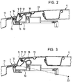
- a wind deflector 8 is arranged on a front edge 7 of the roof opening 3 (FIGS. 1 and 2) and has an air-guiding profile 9 which extends across the width of the roof opening 3. This is designed as a hollow profile part with a closed cross section and adapted to the shape or the curvature of the front edge 7 of the roof opening 3 in the transverse direction. In its closed position (FIG. 2), the air guide profile 9 is essentially received by a frame front part 10, which in this area has, for example, a channel shaped as a water drain.
- the air guide profile 9 also extends slightly beyond the roof contour 11 in its rest position, in order to achieve a streamlined wind duct over a front edge 12 of a front fixed part 13 of the folding roof 4, which is arranged slightly elevated relative to the roof contour 11, at the same time an optically appealing transition is formed.
- a frame seal 14 is placed on a free end 15 of the frame front part 10 in order to seal the air guide profile 9 against the front edge 7 of the roof opening 3.
- the seal 14 advantageously has a lubricious coating, at least on its surface facing the air guide profile, which is formed by a lubricating lacquer.
- the air guide profile 9 has in its upper region a mating surface 16 on which a seal 17 z. B. is attached in the form of a flexible sealing tape.
- the fitting surface 16 is adapted in shape to the front edge 12 of the front fixed part 13 of the folding roof 4.
- the front edge 12 can be rounded, in which case the mating surface 16 is concavely shaped in accordance with the shape of the front edge 12. Any other forms of fit can be used, which ensure mutual tight engagement and easy rolling on one another during the opening and closing movements.
- the wind deflector 8 has a guide device 19 for the air guide profile 9. It contains an extension arm 20 (FIG. 4) on both sides of the air guide profile 9.
- Each extension arm 20 is attached to the roof frame 5 on the one hand in the region of its longitudinal section 25 by means of screws 21 (or rivets, clips or the like) and on the other hand via its curved transition section 22 connected to the air guide profile 9.
- the transition section 22 is adapted as a molded part of the rounding of the front fixed part 13 of the folding roof 4 in its side region.
- its front fixed part 13 covers the lateral extension arms 20 in the region of its longitudinal section 25 and partly the curved transition section 22, which then merges from a hidden position under the folding roof 4 into the uncovered air guide profile 9 and has a shape adapted to the fixed part 13 at the point of emergence.
- the extension arm 20 preferably consists of a prestressed, elastic spring plate so that it presses the air guide profile 9 into its operating position.
- the air guide profile 9 is shown in the raised position after the front fixed part 13 of the folding roof 4 has been raised in the course of the beginning roof opening movement in a lifting movement typical of a folding roof (as described in DE 41 02 660 C1).
- the air guide profile 9 pivots with the extension arm 20 about a pivot axis 23 lying transversely to the vehicle, which is shown in FIG. 3 at the end of a dash-dotted line indicating an extension arm 20, in the raised operating position in which it is limited by a stop 24 , which is attached to the side roof frame 5, for example.
- the air guide profile 9 is about 18 mm beyond the roof skin 11 in its operating position. In its inoperative position, it protrudes slightly beyond the roof skin 11 in order to provide an air-guiding effect for the front edge 12 of the fixed part 13 of the folding roof 4 even in the closed state.
- the air guide profile 9 can also be completely lowered to the level of the roof skin 11, the front edge 12 of the fixed part 13 then possibly also being lowered to the level of the roof skin 11.
Landscapes
- Engineering & Computer Science (AREA)
- Mechanical Engineering (AREA)
- Seal Device For Vehicle (AREA)
Applications Claiming Priority (2)
| Application Number | Priority Date | Filing Date | Title |
|---|---|---|---|
| DE4417049 | 1994-05-14 | ||
| DE19944417049 DE4417049C1 (de) | 1994-05-14 | 1994-05-14 | Windabweiser für Fahrzeugdächer mit beweglichem Dachteil |
Publications (2)
| Publication Number | Publication Date |
|---|---|
| EP0681936A1 true EP0681936A1 (fr) | 1995-11-15 |
| EP0681936B1 EP0681936B1 (fr) | 1997-05-28 |
Family
ID=6518154
Family Applications (1)
| Application Number | Title | Priority Date | Filing Date |
|---|---|---|---|
| EP19950107052 Expired - Lifetime EP0681936B1 (fr) | 1994-05-14 | 1995-05-10 | Déflecteur pour toit amovible de véhicule |
Country Status (2)
| Country | Link |
|---|---|
| EP (1) | EP0681936B1 (fr) |
| DE (1) | DE4417049C1 (fr) |
Cited By (2)
| Publication number | Priority date | Publication date | Assignee | Title |
|---|---|---|---|---|
| EP1495894A1 (fr) * | 2003-07-11 | 2005-01-12 | Webasto AG | Déflecteur d'air pour un toit de véhicule |
| EP4101669A1 (fr) * | 2021-06-10 | 2022-12-14 | Inalfa Roof Systems Group B.V. | Système de toit comprenant un ensemble de déflecteur de vent |
Families Citing this family (7)
| Publication number | Priority date | Publication date | Assignee | Title |
|---|---|---|---|---|
| DE19752344B4 (de) * | 1996-12-04 | 2008-04-03 | Volkswagen Ag | Windabweiser für ein mit einer Schiebedacheinrichtung versehenes Fahrzeugdach |
| DE10206091A1 (de) | 2002-02-13 | 2003-08-28 | Arvinmeritor Gmbh | Windabweiser für die Dachöffnung eines Kraftfahrzeugs |
| DE10222860B4 (de) * | 2002-05-23 | 2006-07-27 | Webasto Ag | Windabweiser für eine Dachöffnung |
| US6971710B1 (en) | 2004-06-07 | 2005-12-06 | Arvinmeritor Technology, Llc | Simplified wind deflector for vehicle sunroof applications |
| DE102007010897A1 (de) | 2007-03-06 | 2008-09-18 | Webasto Ag | Windabweiser mit Abdichtung zum Rahmen |
| DE102008058160B4 (de) * | 2008-11-20 | 2022-01-20 | Dr. Ing. H.C. F. Porsche Aktiengesellschaft | Kraftfahrzeug mit einem offenen Aufbau |
| DE102009005442B4 (de) | 2009-01-21 | 2014-03-27 | Webasto Ag | Windabweiser |
Citations (2)
| Publication number | Priority date | Publication date | Assignee | Title |
|---|---|---|---|---|
| DE4102660C1 (en) * | 1991-01-30 | 1992-05-27 | Webasto Ag Fahrzeugtechnik, 8035 Stockdorf, De | Wind deflector for car with sun roof - is swivelably mounted in region of opposite long sides at distance from roof frame |
| GB2251223A (en) * | 1990-12-20 | 1992-07-01 | Rockwell Golde Gmbh | Sliding roof for an automobile |
-
1994
- 1994-05-14 DE DE19944417049 patent/DE4417049C1/de not_active Expired - Lifetime
-
1995
- 1995-05-10 EP EP19950107052 patent/EP0681936B1/fr not_active Expired - Lifetime
Patent Citations (2)
| Publication number | Priority date | Publication date | Assignee | Title |
|---|---|---|---|---|
| GB2251223A (en) * | 1990-12-20 | 1992-07-01 | Rockwell Golde Gmbh | Sliding roof for an automobile |
| DE4102660C1 (en) * | 1991-01-30 | 1992-05-27 | Webasto Ag Fahrzeugtechnik, 8035 Stockdorf, De | Wind deflector for car with sun roof - is swivelably mounted in region of opposite long sides at distance from roof frame |
Cited By (3)
| Publication number | Priority date | Publication date | Assignee | Title |
|---|---|---|---|---|
| EP1495894A1 (fr) * | 2003-07-11 | 2005-01-12 | Webasto AG | Déflecteur d'air pour un toit de véhicule |
| EP4101669A1 (fr) * | 2021-06-10 | 2022-12-14 | Inalfa Roof Systems Group B.V. | Système de toit comprenant un ensemble de déflecteur de vent |
| US11840129B2 (en) | 2021-06-10 | 2023-12-12 | Inalfa Roof Systems Group B.V. | Roof system having a wind deflector assembly |
Also Published As
| Publication number | Publication date |
|---|---|
| DE4417049C1 (de) | 1995-06-14 |
| EP0681936B1 (fr) | 1997-05-28 |
Similar Documents
| Publication | Publication Date | Title |
|---|---|---|
| EP0150470B1 (fr) | Toit de véhicule | |
| DE4006160C2 (de) | Sonnendachanordnung für ein Kraftfahrzeug | |
| EP0374421B1 (fr) | Déflecteurs d'air pour toits ouvrants, pour toits à panneaux amovibles ou similaires de véhicules automobiles | |
| DE3425271A1 (de) | Fahrzeugdach | |
| EP1338455B1 (fr) | Déflecteur de vent pour toit ouvrant de véhicule | |
| EP1844969B1 (fr) | Mécanisme pour le déflecteur de vent d'un toit coulissant de véhicule | |
| EP0681936B1 (fr) | Déflecteur pour toit amovible de véhicule | |
| DE3105717A1 (de) | Schiebe-hebedach fuer kraftfahrzeuge | |
| DE3129900C2 (de) | Hebeschiebedach für Kraftfahrzeuge | |
| DE3426998A1 (de) | Fahrzeugdach | |
| DE10082186B4 (de) | Schiebedachdeckel für eine Dachöffnung eines Fahrzeugdaches | |
| EP1616738B1 (fr) | Construction de toit coulissant pour véhicule automobile | |
| DE4214277C2 (de) | Rahmenanordnung für ein Schiebedach, Schiebehebedach, Spoilerdach oder dergleichen | |
| EP1193094A2 (fr) | Mécanisme pour déflecteur de vent de toit ouvrant | |
| DE10158174A1 (de) | Schiebehebedach für Fahrzeuge | |
| DE3706917A1 (de) | Wasserrinne fuer das schiebe-hebe-dach eines kraftfahrzeuges | |
| DE3823316C2 (fr) | ||
| EP0826538B1 (fr) | Toit de véhicule | |
| EP1674314B1 (fr) | Dispositif de réglage pour un panneau de toit d'un véhicule | |
| EP0292730A2 (fr) | Toit de véhicule | |
| DE4108197C2 (de) | Sonnendach für Fahrzeuge | |
| EP1582387A2 (fr) | Toit coulissant pour véhicule | |
| DE9417026U1 (de) | Windabweiser für Fahrzeugdächer mit beweglichem Dachteil | |
| DE69925217T2 (de) | Konstruktion eines öffnungsfähigen Fahrzeugdaches | |
| DE102016119451A1 (de) | Kraftfahrzeug-Schiebedachsystem |
Legal Events
| Date | Code | Title | Description |
|---|---|---|---|
| PUAI | Public reference made under article 153(3) epc to a published international application that has entered the european phase |
Free format text: ORIGINAL CODE: 0009012 |
|
| AK | Designated contracting states |
Kind code of ref document: A1 Designated state(s): FR GB NL |
|
| 17P | Request for examination filed |
Effective date: 19951129 |
|
| GRAG | Despatch of communication of intention to grant |
Free format text: ORIGINAL CODE: EPIDOS AGRA |
|
| GRAH | Despatch of communication of intention to grant a patent |
Free format text: ORIGINAL CODE: EPIDOS IGRA |
|
| 17Q | First examination report despatched |
Effective date: 19961115 |
|
| GRAH | Despatch of communication of intention to grant a patent |
Free format text: ORIGINAL CODE: EPIDOS IGRA |
|
| GRAA | (expected) grant |
Free format text: ORIGINAL CODE: 0009210 |
|
| AK | Designated contracting states |
Kind code of ref document: B1 Designated state(s): FR GB NL |
|
| GBT | Gb: translation of ep patent filed (gb section 77(6)(a)/1977) |
Effective date: 19970528 |
|
| ET | Fr: translation filed | ||
| PLBE | No opposition filed within time limit |
Free format text: ORIGINAL CODE: 0009261 |
|
| STAA | Information on the status of an ep patent application or granted ep patent |
Free format text: STATUS: NO OPPOSITION FILED WITHIN TIME LIMIT |
|
| 26N | No opposition filed | ||
| REG | Reference to a national code |
Ref country code: GB Ref legal event code: IF02 |
|
| PGFP | Annual fee paid to national office [announced via postgrant information from national office to epo] |
Ref country code: GB Payment date: 20140520 Year of fee payment: 20 |
|
| PGFP | Annual fee paid to national office [announced via postgrant information from national office to epo] |
Ref country code: NL Payment date: 20140520 Year of fee payment: 20 Ref country code: FR Payment date: 20140516 Year of fee payment: 20 |
|
| REG | Reference to a national code |
Ref country code: NL Ref legal event code: V4 Effective date: 20150510 |
|
| REG | Reference to a national code |
Ref country code: GB Ref legal event code: PE20 Expiry date: 20150509 |
|
| PG25 | Lapsed in a contracting state [announced via postgrant information from national office to epo] |
Ref country code: GB Free format text: LAPSE BECAUSE OF EXPIRATION OF PROTECTION Effective date: 20150509 |