EP0681939B1 - Anlage für elektrischen Transport - Google Patents
Anlage für elektrischen Transport Download PDFInfo
- Publication number
- EP0681939B1 EP0681939B1 EP94810280A EP94810280A EP0681939B1 EP 0681939 B1 EP0681939 B1 EP 0681939B1 EP 94810280 A EP94810280 A EP 94810280A EP 94810280 A EP94810280 A EP 94810280A EP 0681939 B1 EP0681939 B1 EP 0681939B1
- Authority
- EP
- European Patent Office
- Prior art keywords
- inductors
- vehicle
- generator
- ground
- fed
- Prior art date
- Legal status (The legal status is an assumption and is not a legal conclusion. Google has not performed a legal analysis and makes no representation as to the accuracy of the status listed.)
- Expired - Lifetime
Links
Images

Classifications
-
- B—PERFORMING OPERATIONS; TRANSPORTING
- B60—VEHICLES IN GENERAL
- B60M—POWER SUPPLY LINES, AND DEVICES ALONG RAILS, FOR ELECTRICALLY- PROPELLED VEHICLES
- B60M1/00—Power supply lines for contact with collector on vehicle
- B60M1/36—Single contact pieces along the line for power supply
-
- B—PERFORMING OPERATIONS; TRANSPORTING
- B60—VEHICLES IN GENERAL
- B60L—PROPULSION OF ELECTRICALLY-PROPELLED VEHICLES; SUPPLYING ELECTRIC POWER FOR AUXILIARY EQUIPMENT OF ELECTRICALLY-PROPELLED VEHICLES; ELECTRODYNAMIC BRAKE SYSTEMS FOR VEHICLES IN GENERAL; MAGNETIC SUSPENSION OR LEVITATION FOR VEHICLES; MONITORING OPERATING VARIABLES OF ELECTRICALLY-PROPELLED VEHICLES; ELECTRIC SAFETY DEVICES FOR ELECTRICALLY-PROPELLED VEHICLES
- B60L5/00—Current collectors for power supply lines of electrically-propelled vehicles
- B60L5/005—Current collectors for power supply lines of electrically-propelled vehicles without mechanical contact between the collector and the power supply line
Definitions
- the subject of the present invention is an electrical transport installation comprising at least one vehicle driven by at least one electric motor powered by a device on the ground
- Transport facilities comprising a vehicle driven by an electric motor powered by a device on the ground without contact between the device and the vehicle.
- French patent application No. 78 10675 publication No. 2 387 138 discloses, for example, such an installation, in which induction devices are fixed in the ground.
- induction devices are fixed in the ground.
- Patent application EP-A-0 289 868 describes an installation of the same type as those defined above, but where the problem solved was, like in application FR 2 387 138, to energize only the induction devices located under the vehicle. However, the problem of phase matching when switching from one inductor to another did not been resolved.
- the object of the present invention is to provide a transport installation comprising one or more vehicles powered by an electric motor receiving its energy by induction from devices fixed to the ground, does not not having the drawbacks of known devices.
- the electric transport installation comprises at least a vehicle powered by at least one electric motor powered by a ground device, the feed device consisting of inductors dishes with windings located below the ground surface or in a plane parallel to the latter creating a magnetic field transmitting energy to the vehicle when it is above inductors, the inductors being arranged in line and having means to supply them with power only when a vehicle is above it, characterized in that each inductor is powered by one or the other of two successive generators and in that each generator supplies one group of inductors so that a moving vehicle always covering at least three inductors is always above inductors powered by the same generator.
- the stream preferably having a frequency between 100 and 200 KHerz.
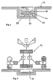
- the installation shown in Figure 1 aims to achieve a network of automatic vehicles, for example a public transport network.
- the network includes a multitude of identical vehicles comprising, by example, electric motors in two wheels and means triggers ensuring automatic guidance over the installation on the ground.
- Ground installation includes a power supply line electric 1 supplying two buses 23 and 24 which supply a succession of generators G 2, 3, 4, 5 and 6.
- Each generator supplies a bus 25 with low frequency current, in particular 140 KHerz.
- Bus 25 from generator 3 supplies five inductors B 7, 8, 9, 10 and 11.
- the bus 26 of generator 4 supplies inductors 9 to 13, and bus 27 of generator 5 inductors 12 to 16.
- each inductor can be powered by two different generators.
- inductor 7 can be powered by generator 2 or by generator 3 depending on the position of the control devices 17 and 18.
- control devices for inductors 8 to 16 do not do not have a reference sign, but they are similar to those of inductor 7.
- a control bus 22 connects the generators to a device for control 20. Likewise all inductor control devices are connected to the control device 20. Each inductor has in its environment of detection means allowing it to know if a vehicle is above. These means can be of any kind, magnetic or not.
- the inductors of an installation according to the invention consist of spiral windings in a plane without a metallic core. They can preferably be circular, but may also be circular square, rectangular, elliptical, oval.
- Figure 2 shows a schematic section showing how could be arranged the various elements constituting the device on the ground.
- the winding B constituting the inductor is arranged just at road level 34.
- the generator 28 and on the sides the information bus 29, The bus low frequency power supply 31 and the power supply bus generators 30, finally the device for controlling the activation of the coils 32.
- the assembly takes very little place in the pavement.
- the installation will include a plurality of vehicles traveling on a circuit shaped loop. Vehicles being in constant motion never stopping a relatively short time to let users go up and go down. In addition, vehicles will circulate automatically in depending on the installation on the ground, but each user for a fee vehicle may have the vehicle outside the ground installation for a determined time.
Landscapes
- Engineering & Computer Science (AREA)
- Mechanical Engineering (AREA)
- Power Engineering (AREA)
- Transportation (AREA)
- Electric Propulsion And Braking For Vehicles (AREA)
- Air Transport Of Granular Materials (AREA)
- Steering-Linkage Mechanisms And Four-Wheel Steering (AREA)
- Laying Of Electric Cables Or Lines Outside (AREA)
Claims (4)
- Elektrische Fördereinrichtung, bestehend aus mindestens einem Wagen, der durch mindestens einen Elektromotor angetrieben wird, der durch eine Bodenvorrichtung versorgt wird, dadurch gekennzeichnet, daß die Versorgungsvorrichtung von flachen Induktoren gebildet wird, die Wicklungen umfassen, die in der Ebene des Bodens oder in einer zu dem Boden parallelen Ebene angeordnet sind und ein Magnetfeld erzeugen, das die Energie zu dem Wagen überträgt, wenn er sich über dem Induktor befindet, wobei die Induktoren in einer Linie angeordnet sind und Mittel aufweisen, um sie mit Strom zu versorgen, wenn sich ein Wagen darüber befindet, wobei jeder Induktor alternative durch zwei Generatoren versorgt wird und jeder Generator eine Gruppe von Induktoren versorgt, so daß sich ein in Bewegung befindlicher Wagen, der mindestens drei Induktoren gleichzeitig abdeckt, immer noch über Induktoren befindet, die von demselben Generator versorgt werden.
- Einrichtung nach Anspruch 1, dadurch gekennzeichnet, daß sie eine große Anzahl von Wagen umfaßt und daß die Wagen Mittel zur Speicherung der Energie, wodurch sie eine bestimmte Zeit hindurch autonom werden, und Mittel zum beliebigen Ein- und Ausschalten umfassen, um sie automatisch über die Induktoren zu führen.
- Einrichtung nach einem der Ansprüche 1 und 2, dadurch gekennzeichnet, daß ein erster Generator eine Gruppe von fünf Induktoren versorgt, ein zweiter Generator drei Induktoren dieser Gruppe und zwei Induktoren der folgenden Gruppe usw. versorgt, wodurch sich auf diese Weise jeder Wagen, der drei Induktoren abdeckt, über drei Induktoren befindet, die von demselben Generator versorgt werden.
- Einrichtung nach einem der Ansprüche 1 bis 3, dadurch gekennzeichnet, daß der Strom eine Frequenz zwischen 100 KHertz und 200 KHertz besitzt.
Priority Applications (4)
| Application Number | Priority Date | Filing Date | Title |
|---|---|---|---|
| AT94810280T ATE175384T1 (de) | 1994-05-10 | 1994-05-10 | Anlage für elektrischen transport |
| DE69415794T DE69415794T2 (de) | 1994-05-10 | 1994-05-10 | Anlage für elektrischen Transport |
| EP94810280A EP0681939B1 (de) | 1994-05-10 | 1994-05-10 | Anlage für elektrischen Transport |
| ES94810280T ES2129113T3 (es) | 1994-05-10 | 1994-05-10 | Instalacion de transporte electrico. |
Applications Claiming Priority (1)
| Application Number | Priority Date | Filing Date | Title |
|---|---|---|---|
| EP94810280A EP0681939B1 (de) | 1994-05-10 | 1994-05-10 | Anlage für elektrischen Transport |
Publications (2)
| Publication Number | Publication Date |
|---|---|
| EP0681939A1 EP0681939A1 (de) | 1995-11-15 |
| EP0681939B1 true EP0681939B1 (de) | 1999-01-07 |
Family
ID=8218253
Family Applications (1)
| Application Number | Title | Priority Date | Filing Date |
|---|---|---|---|
| EP94810280A Expired - Lifetime EP0681939B1 (de) | 1994-05-10 | 1994-05-10 | Anlage für elektrischen Transport |
Country Status (4)
| Country | Link |
|---|---|
| EP (1) | EP0681939B1 (de) |
| AT (1) | ATE175384T1 (de) |
| DE (1) | DE69415794T2 (de) |
| ES (1) | ES2129113T3 (de) |
Cited By (5)
| Publication number | Priority date | Publication date | Assignee | Title |
|---|---|---|---|---|
| CN102596633A (zh) * | 2009-07-27 | 2012-07-18 | 伊丽·伯诺利尔 | 用于电动车辆的路基支撑 |
| US8360216B2 (en) | 2008-07-04 | 2013-01-29 | Bombardier Transportation Gmbh | System and method for transferring electric energy to a vehicle |
| US8544622B2 (en) | 2008-09-19 | 2013-10-01 | Bombardier Transportation Gmbh | Producing electromagnetic fields for transferring electric energy to a vehicle |
| US8590682B2 (en) | 2008-07-04 | 2013-11-26 | Bombardier Transportation Gmbh | Transferring electric energy to a vehicle |
| US8827058B2 (en) | 2008-09-19 | 2014-09-09 | Bombardier Transportation Gmbh | Inductively receiving electric energy for a vehicle |
Families Citing this family (6)
| Publication number | Priority date | Publication date | Assignee | Title |
|---|---|---|---|---|
| FR2791929B1 (fr) * | 1999-04-07 | 2004-09-10 | Soc Gle Techniques Etudes | Dispositif de detection de presence de vehicule a fiabilite amelioree |
| EP1465783B1 (de) | 2002-01-15 | 2006-03-29 | Bernard Saugy | Elektrisches strassenfahrzeug, insbesondere automatisches fahrzeug |
| EP1439088A1 (de) * | 2003-01-15 | 2004-07-21 | Metso Paper AG | Schienenanordnung, Wagen und Transportanlage, zur kontaklosen Stromübertragung |
| DE102009039975A1 (de) * | 2009-09-03 | 2011-03-10 | Conductix-Wampfler Ag | Vorrichtung und Verfahren zur induktiven Übertragung elektrischer Energie an bewegliche Verbraucher |
| GB2476313A (en) | 2009-12-21 | 2011-06-22 | Bombardier Transp Gmbh | Cooling of electronic devices located in a ground cavity |
| GB201121938D0 (en) * | 2011-12-21 | 2012-02-01 | Dames Andrew N | Supply of grid power to moving vehicles |
Family Cites Families (2)
| Publication number | Priority date | Publication date | Assignee | Title |
|---|---|---|---|---|
| FR2613883B1 (fr) * | 1987-04-13 | 1992-10-16 | Scidepa Ste Civile Brevets | Dispositif d'alimentation d'un recepteur electrique place sur une surface comportant un reseau de plages en materiau conducteur de l'electricite |
| US4836344A (en) * | 1987-05-08 | 1989-06-06 | Inductran Corporation | Roadway power and control system for inductively coupled transportation system |
-
1994
- 1994-05-10 ES ES94810280T patent/ES2129113T3/es not_active Expired - Lifetime
- 1994-05-10 EP EP94810280A patent/EP0681939B1/de not_active Expired - Lifetime
- 1994-05-10 AT AT94810280T patent/ATE175384T1/de not_active IP Right Cessation
- 1994-05-10 DE DE69415794T patent/DE69415794T2/de not_active Expired - Fee Related
Cited By (5)
| Publication number | Priority date | Publication date | Assignee | Title |
|---|---|---|---|---|
| US8360216B2 (en) | 2008-07-04 | 2013-01-29 | Bombardier Transportation Gmbh | System and method for transferring electric energy to a vehicle |
| US8590682B2 (en) | 2008-07-04 | 2013-11-26 | Bombardier Transportation Gmbh | Transferring electric energy to a vehicle |
| US8544622B2 (en) | 2008-09-19 | 2013-10-01 | Bombardier Transportation Gmbh | Producing electromagnetic fields for transferring electric energy to a vehicle |
| US8827058B2 (en) | 2008-09-19 | 2014-09-09 | Bombardier Transportation Gmbh | Inductively receiving electric energy for a vehicle |
| CN102596633A (zh) * | 2009-07-27 | 2012-07-18 | 伊丽·伯诺利尔 | 用于电动车辆的路基支撑 |
Also Published As
| Publication number | Publication date |
|---|---|
| ES2129113T3 (es) | 1999-06-01 |
| DE69415794T2 (de) | 1999-08-19 |
| ATE175384T1 (de) | 1999-01-15 |
| EP0681939A1 (de) | 1995-11-15 |
| DE69415794D1 (de) | 1999-02-18 |
Similar Documents
| Publication | Publication Date | Title |
|---|---|---|
| EP0681939B1 (de) | Anlage für elektrischen Transport | |
| US6421600B1 (en) | Roadway-powered electric vehicle system having automatic guidance and demand-based dispatch features | |
| CA2280417C (fr) | Systeme d'alimentation d'un vehicule a traction electrique | |
| US5839554A (en) | Power collector for inductive power transfer | |
| US11178813B2 (en) | Combination lawn mower and trailer | |
| EP2447105B1 (de) | Bodengeführtes Stromversorgungssystem für Transportfahrzeug, und entsprechende Verfahren | |
| US20120067684A1 (en) | System Adapted for One or More Vehicles, Which May be Driven Forward Electrically | |
| FR2924990A1 (fr) | Systeme d'alimentation pour vehicule a traction electrique a stockage d'energie embarque | |
| US20130300132A1 (en) | Vehicle movement activated electrical power generator, and method for providing electrical power for roadside applications | |
| US8851252B2 (en) | System adapted for one or more electrically propellable vehicles (cleansing means) | |
| US9162577B2 (en) | System adapted for one or more electrically propellable vehicles (contact means) | |
| CN102858583B (zh) | 用于一个或多个电力驱动车辆的系统(雪犁装置) | |
| US20120025629A1 (en) | Systems and Methods for Distributing Energy in a Roadway | |
| CN102844217B (zh) | 用于一个或多个电力驱动车辆的系统(可使水绕过导电体) | |
| CN102821999A (zh) | 用于一个或多个电力驱动车辆的系统(路轨结构) | |
| AU2008264146A1 (en) | System and method for improved electric cars and/or electric car batteries and/or improved infrastructures for recharging electric cars. | |
| FR2822764A1 (fr) | Procede et dispositif de pilotage de l'alimentation en energie d'un vehicule a traction electrique destine a fonctionner en mode d'alimentation externe ou en mode d'alimentation autonome | |
| EP1892141A1 (de) | System und Unterstation zur elektrischen Speisung eines Traktionsnetzes | |
| CN102834290B (zh) | 电动车辆系统的过载限制装置 | |
| EP3461953B1 (de) | Autonome und intelligente schienen-/strassen-kehrmaschine, und überwachungssystem einer solchen kehrmaschine | |
| FR2910391A1 (fr) | Systeme de captage occasionnel d'energie electrique notamment pour un vehicule urbain de transport en commun. | |
| FR2998427A1 (fr) | Systeme de charge sans contact d'une batterie d'un vehicule en mouvement | |
| CH688685A5 (fr) | Installation de transport électrique. | |
| EP1397281B1 (de) | Automatische transport- und personenführungsanlage und steuerung von transportmodulen in einer solchen anlage | |
| EP3715172A1 (de) | Dynamisches anpassungsverfahren für den betrieb mindestens eines umformerwerks eines stromversorungssystems von schienenfahrzeugen, computerprogramm und entsprechende vorrichtung |
Legal Events
| Date | Code | Title | Description |
|---|---|---|---|
| PUAI | Public reference made under article 153(3) epc to a published international application that has entered the european phase |
Free format text: ORIGINAL CODE: 0009012 |
|
| AK | Designated contracting states |
Kind code of ref document: A1 Designated state(s): AT BE CH DE DK ES FR GB GR IE IT LI LU MC NL PT SE |
|
| 17P | Request for examination filed |
Effective date: 19951227 |
|
| 17Q | First examination report despatched |
Effective date: 19971106 |
|
| GRAG | Despatch of communication of intention to grant |
Free format text: ORIGINAL CODE: EPIDOS AGRA |
|
| GRAG | Despatch of communication of intention to grant |
Free format text: ORIGINAL CODE: EPIDOS AGRA |
|
| GRAH | Despatch of communication of intention to grant a patent |
Free format text: ORIGINAL CODE: EPIDOS IGRA |
|
| GRAH | Despatch of communication of intention to grant a patent |
Free format text: ORIGINAL CODE: EPIDOS IGRA |
|
| GRAA | (expected) grant |
Free format text: ORIGINAL CODE: 0009210 |
|
| AK | Designated contracting states |
Kind code of ref document: B1 Designated state(s): AT BE CH DE DK ES FR GB GR IE IT LI LU MC NL PT SE |
|
| PG25 | Lapsed in a contracting state [announced via postgrant information from national office to epo] |
Ref country code: SE Free format text: THE PATENT HAS BEEN ANNULLED BY A DECISION OF A NATIONAL AUTHORITY Effective date: 19990107 Ref country code: GR Free format text: LAPSE BECAUSE OF NON-PAYMENT OF DUE FEES Effective date: 19990107 |
|
| REF | Corresponds to: |
Ref document number: 175384 Country of ref document: AT Date of ref document: 19990115 Kind code of ref document: T |
|
| REG | Reference to a national code |
Ref country code: CH Ref legal event code: EP |
|
| REF | Corresponds to: |
Ref document number: 69415794 Country of ref document: DE Date of ref document: 19990218 |
|
| REG | Reference to a national code |
Ref country code: IE Ref legal event code: FG4D Free format text: FRENCH |
|
| ITF | It: translation for a ep patent filed | ||
| PG25 | Lapsed in a contracting state [announced via postgrant information from national office to epo] |
Ref country code: PT Free format text: LAPSE BECAUSE OF FAILURE TO SUBMIT A TRANSLATION OF THE DESCRIPTION OR TO PAY THE FEE WITHIN THE PRESCRIBED TIME-LIMIT Effective date: 19990407 Ref country code: DK Free format text: LAPSE BECAUSE OF FAILURE TO SUBMIT A TRANSLATION OF THE DESCRIPTION OR TO PAY THE FEE WITHIN THE PRESCRIBED TIME-LIMIT Effective date: 19990407 |
|
| GBT | Gb: translation of ep patent filed (gb section 77(6)(a)/1977) |
Effective date: 19990331 |
|
| REG | Reference to a national code |
Ref country code: ES Ref legal event code: FG2A Ref document number: 2129113 Country of ref document: ES Kind code of ref document: T3 |
|
| PG25 | Lapsed in a contracting state [announced via postgrant information from national office to epo] |
Ref country code: IE Free format text: LAPSE BECAUSE OF NON-PAYMENT OF DUE FEES Effective date: 19990820 |
|
| REG | Reference to a national code |
Ref country code: IE Ref legal event code: FD4D |
|
| PLBE | No opposition filed within time limit |
Free format text: ORIGINAL CODE: 0009261 |
|
| STAA | Information on the status of an ep patent application or granted ep patent |
Free format text: STATUS: NO OPPOSITION FILED WITHIN TIME LIMIT |
|
| 26N | No opposition filed | ||
| PGFP | Annual fee paid to national office [announced via postgrant information from national office to epo] |
Ref country code: BE Payment date: 20010605 Year of fee payment: 8 |
|
| REG | Reference to a national code |
Ref country code: GB Ref legal event code: IF02 |
|
| PG25 | Lapsed in a contracting state [announced via postgrant information from national office to epo] |
Ref country code: BE Free format text: LAPSE BECAUSE OF NON-PAYMENT OF DUE FEES Effective date: 20020531 |
|
| PG25 | Lapsed in a contracting state [announced via postgrant information from national office to epo] |
Ref country code: MC Free format text: LAPSE BECAUSE OF NON-PAYMENT OF DUE FEES Effective date: 20031104 |
|
| PGFP | Annual fee paid to national office [announced via postgrant information from national office to epo] |
Ref country code: CH Payment date: 20060502 Year of fee payment: 13 |
|
| REG | Reference to a national code |
Ref country code: CH Ref legal event code: PL |
|
| PG25 | Lapsed in a contracting state [announced via postgrant information from national office to epo] |
Ref country code: CH Free format text: LAPSE BECAUSE OF NON-PAYMENT OF DUE FEES Effective date: 20070531 Ref country code: LI Free format text: LAPSE BECAUSE OF NON-PAYMENT OF DUE FEES Effective date: 20070531 |
|
| PGFP | Annual fee paid to national office [announced via postgrant information from national office to epo] |
Ref country code: LU Payment date: 20080529 Year of fee payment: 15 Ref country code: ES Payment date: 20080520 Year of fee payment: 15 Ref country code: DE Payment date: 20080519 Year of fee payment: 15 |
|
| PGFP | Annual fee paid to national office [announced via postgrant information from national office to epo] |
Ref country code: AT Payment date: 20080523 Year of fee payment: 15 |
|
| PGFP | Annual fee paid to national office [announced via postgrant information from national office to epo] |
Ref country code: IT Payment date: 20080521 Year of fee payment: 15 |
|
| PGFP | Annual fee paid to national office [announced via postgrant information from national office to epo] |
Ref country code: NL Payment date: 20080526 Year of fee payment: 15 |
|
| PGFP | Annual fee paid to national office [announced via postgrant information from national office to epo] |
Ref country code: GB Payment date: 20080604 Year of fee payment: 15 |
|
| GBPC | Gb: european patent ceased through non-payment of renewal fee |
Effective date: 20090510 |
|
| PG25 | Lapsed in a contracting state [announced via postgrant information from national office to epo] |
Ref country code: AT Free format text: LAPSE BECAUSE OF NON-PAYMENT OF DUE FEES Effective date: 20090510 |
|
| NLV4 | Nl: lapsed or anulled due to non-payment of the annual fee |
Effective date: 20091201 |
|
| PG25 | Lapsed in a contracting state [announced via postgrant information from national office to epo] |
Ref country code: NL Free format text: LAPSE BECAUSE OF NON-PAYMENT OF DUE FEES Effective date: 20091201 |
|
| PG25 | Lapsed in a contracting state [announced via postgrant information from national office to epo] |
Ref country code: GB Free format text: LAPSE BECAUSE OF NON-PAYMENT OF DUE FEES Effective date: 20090510 |
|
| PG25 | Lapsed in a contracting state [announced via postgrant information from national office to epo] |
Ref country code: DE Free format text: LAPSE BECAUSE OF NON-PAYMENT OF DUE FEES Effective date: 20091201 |
|
| REG | Reference to a national code |
Ref country code: ES Ref legal event code: FD2A Effective date: 20090511 |
|
| PG25 | Lapsed in a contracting state [announced via postgrant information from national office to epo] |
Ref country code: ES Free format text: LAPSE BECAUSE OF NON-PAYMENT OF DUE FEES Effective date: 20090511 |
|
| PG25 | Lapsed in a contracting state [announced via postgrant information from national office to epo] |
Ref country code: IT Free format text: LAPSE BECAUSE OF NON-PAYMENT OF DUE FEES Effective date: 20090510 |
|
| PG25 | Lapsed in a contracting state [announced via postgrant information from national office to epo] |
Ref country code: LU Free format text: LAPSE BECAUSE OF NON-PAYMENT OF DUE FEES Effective date: 20090510 |
|
| PGFP | Annual fee paid to national office [announced via postgrant information from national office to epo] |
Ref country code: FR Payment date: 20110617 Year of fee payment: 18 Ref country code: MC Payment date: 20110530 Year of fee payment: 18 |
|
| PG25 | Lapsed in a contracting state [announced via postgrant information from national office to epo] |
Ref country code: MC Free format text: LAPSE BECAUSE OF NON-PAYMENT OF DUE FEES Effective date: 20120531 |
|
| REG | Reference to a national code |
Ref country code: FR Ref legal event code: ST Effective date: 20130131 |
|
| PG25 | Lapsed in a contracting state [announced via postgrant information from national office to epo] |
Ref country code: FR Free format text: LAPSE BECAUSE OF NON-PAYMENT OF DUE FEES Effective date: 20120531 |