EP0681957B1 - Verfahren und Vorrichtung zum Umwickeln von Quadern, insbesondere Isolierstoffballen, mit Einwickelmaterial - Google Patents
Verfahren und Vorrichtung zum Umwickeln von Quadern, insbesondere Isolierstoffballen, mit Einwickelmaterial Download PDFInfo
- Publication number
- EP0681957B1 EP0681957B1 EP95104388A EP95104388A EP0681957B1 EP 0681957 B1 EP0681957 B1 EP 0681957B1 EP 95104388 A EP95104388 A EP 95104388A EP 95104388 A EP95104388 A EP 95104388A EP 0681957 B1 EP0681957 B1 EP 0681957B1
- Authority
- EP
- European Patent Office
- Prior art keywords
- web
- parallelepiped
- gap
- wrapping
- cuboid
- Prior art date
- Legal status (The legal status is an assumption and is not a legal conclusion. Google has not performed a legal analysis and makes no representation as to the accuracy of the status listed.)
- Expired - Lifetime
Links
- 238000000034 method Methods 0.000 title claims description 9
- 239000000463 material Substances 0.000 title claims description 8
- 239000011810 insulating material Substances 0.000 title description 2
- 230000033001 locomotion Effects 0.000 claims description 12
- 238000005520 cutting process Methods 0.000 claims description 2
- 239000004744 fabric Substances 0.000 claims 2
- 238000004026 adhesive bonding Methods 0.000 claims 1
- 238000004519 manufacturing process Methods 0.000 description 4
- 239000011888 foil Substances 0.000 description 3
- 239000000853 adhesive Substances 0.000 description 2
- 230000001070 adhesive effect Effects 0.000 description 2
- 238000013459 approach Methods 0.000 description 2
- 230000004888 barrier function Effects 0.000 description 1
- 238000005452 bending Methods 0.000 description 1
- 230000009286 beneficial effect Effects 0.000 description 1
- 238000010276 construction Methods 0.000 description 1
- 238000009413 insulation Methods 0.000 description 1
- 238000003754 machining Methods 0.000 description 1
- 238000003825 pressing Methods 0.000 description 1
- 230000002441 reversible effect Effects 0.000 description 1
- 238000000926 separation method Methods 0.000 description 1
- 230000007704 transition Effects 0.000 description 1
- 210000000689 upper leg Anatomy 0.000 description 1
- 238000004804 winding Methods 0.000 description 1
Images






Classifications
-
- B—PERFORMING OPERATIONS; TRANSPORTING
- B65—CONVEYING; PACKING; STORING; HANDLING THIN OR FILAMENTARY MATERIAL
- B65B—MACHINES, APPARATUS OR DEVICES FOR, OR METHODS OF, PACKAGING ARTICLES OR MATERIALS; UNPACKING
- B65B11/00—Wrapping, e.g. partially or wholly enclosing, articles or quantities of material, in strips, sheets or blanks, of flexible material
- B65B11/06—Wrapping articles, or quantities of material, by conveying wrapper and contents in common defined paths
- B65B11/08—Wrapping articles, or quantities of material, by conveying wrapper and contents in common defined paths in a single straight path
- B65B11/10—Wrapping articles, or quantities of material, by conveying wrapper and contents in common defined paths in a single straight path to fold the wrappers in tubular form about contents
Definitions
- the invention relates to a method according to the preamble of Claim 1 and a device according to the preamble of the claim 3rd
- Such a method and such a device are known from the DE 12 99 548 A1 and DE 24 50 373 A1 are known. There are below a gap, the first and a second conveyor line separates from each other, a pair of pliers and a fly knife arranged, which is either a separate, through the open Forceps that can be moved through the pliers (DE 12 99 548 A1) or can simultaneously form a pair of pliers jaws (DE 24 50 373 A1). Each cycle begins with the bottom of one vertically from top to bottom fed film web in the Pliers are clamped before a cuboid to be wrapped against the film web is pressed.
- the one used in this known way for enveloping cuboids Foil is made of plastic such as PVC or PE and is therefore sufficiently smooth and tear-resistant to in the manner described across the bottom, front, and top of each box to be able to slide, the relative speed between Foil and cuboid on the underside and front just as big, on the top, however, twice as large as the speed of movement of the cuboid.
- the resulting frictional resistances are only manageable if the cuboid even as the film is smooth.
- the known ones described are suitable Procedure and device not.
- DE 11 70 859 A1 describes a device for wrapping around Cuboids known, the three arranged one behind the other of the Having cubes of conveying tunnels to be passed through one after the other.
- the first production tunnel has a transverse gap, through which a sheet of wrapping material passes from above is fed such that its lower end below one Bottom plate of the tunnel, and her cutting the track The free upper end above a cover plate of the tunnel is arranged. Then a cuboid to be encased in the first Production tunnel moves forward so that it is with its front puts on the track section and takes it, so that it forms thighs that also extend to the underside and to the Place the top of the cuboid and protrude to the rear.
- first and second production tunnels have gaps in the cover plate and the base plate through which initially a driver of an endless upper conveyor immersed in the second conveyor tunnel from above while doing so presses the top of the web against the back, and then correspondingly one with a lower endless Conveyor rotating carrier from below into the second Production tunnel intervenes and the lower overhang of the railway also pushes against the back of the cuboid.
- the Cuboid first from the driver of the upper conveyor and then pushed forward by the driver of the lower conveyor. So that the latter can reach the cuboid, the lower conveyor must temporarily driven at increased speed.
- cuboids can also be wrapped, which are not particularly smooth, and can be also not particularly tear-resistant wrapping material, for example Use wrapping paper; the device is complex and takes up a lot of space.
- the two conveyor lines are there arranged at right angles to a main conveyor which is of Insulated bales of cuboids.
- the first Conveyor line can be raised and lowered to every machine cycle to take over a cuboid from the main conveyor and into To promote direction to the second conveyor line.
- the second conveyor line is as a whole towards the first conveyor line adjustable to and from this, and the conveying direction of both Conveyor routes are reversible.
- the machine has a pair located to the side of the gap Stand in which a driver designed as a winding roll stored and guided up and down.
- the driver of the known device dips through the wide open gap down, grasp that End of the web held there, winds a web section and returns to its upper end position. Then will the web separated below the gap, so that it from the driver hanging loosely through the gap.
- the second conveyor line approaches the first one by the one it is moving towards Take over cuboid. Its front side bumps into the vertically hanging track section, which is used for locomotion of the cuboid is gradually handled by the driver. As soon as the cuboid has passed the gap, it will again wide open and the driver dives with him trapped web end down through the gap where he releases the end of the web.
- the invention has for its object a method and a device for wrapping cuboids, in particular bales of insulating material, with a web of wrapping material, in particular Paper to be designed so that given Dimensions of the cuboid shorter machining times can be achieved are and the device effort is reduced.
- cuboid 1 With the device shown are approximately cuboid Insulation bales, hereinafter referred to as cuboid 1, wrapped with a sheet 2 of wrapping paper.
- the Lane 2 is first on the front 3, then on the Top 4 and bottom 5 and finally to the back 6 of a cuboid 1, with web ends at the rear 6 form an overlap 7 and glued together there will.
- the web 2 is preferably so much wider than that Top and bottom 4 and 5 of the cuboid 1 that lateral protrusions arise, which are then folded over to the Cover long sides 8 of the cuboid.
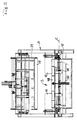
- the cuboids 1 at relatively short distances from each other in the direction of arrow 9 in Figure 1 by the device shown conveyed through.
- the device has a frame 10 which forms a tunnel. To this leads a conveyor line 11, on each one Cuboid 1 moved by a slider 12 in the direction of arrow 9 becomes.
- the slide 12 works intermittently; he will each from its front one indicated in FIG. 1 with dashed lines Position in the rest position drawn with solid lines withdrawn.
- a second conveyor line connects to the first conveyor line 11 13, with a between these two conveyor lines with respect to their direction of conveyance (arrow 9) transverse gap 14 remains free.
- Barriers 15 are arranged, each of which is a cuboid 1 stopped is before he is taken on the second conveyor line 13 becomes.
- a third conveyor line connects to the second conveyor line 13 17 on, flaps 18 on both sides for bending of the lateral protrusions of the web 2 mentioned are.
- the flaps 18 are each on a transverse carriage 19 attached so that the distance between opposite one another Flaps 18 to adapt to cuboids 1 different Width is adjustable.
- a horizontal pressure plate 20 arranged by means of a scissor assembly 21 suspended on the frame 10 and by means of an actuator 22 parallel to itself is adjustable to be different Adjust the heights of the cuboid 1.
- the web 2 either runs over a deflection roller 26 on one of the Bearing blocks 24 or directly up to a first portal 27 via a second deflection roller 28 mounted there, by a also on this portal 27 frame-shaped dancers 29 through a third deflection roller mounted thereon 30.
- the dancer 29 is adjustable with the first portal 27 Actuator 31 connected, which makes it possible in the web 2nd maintain a preselected tension.
- the web 2 extends upwards again a second portal 32 and around a deflection arranged there 33, which can also be a pulley.
- a drive roller 34 is arranged, which together with a second drive roller 35 a nip forms, through which the web 2 is passed vertically downwards becomes. All pulleys and drive rollers have horizontal, 9 transverse to the direction of conveyance Axes.
- the nip is between the drive rollers 34 and 35 vertically above the gap 14 between the two conveyor lines 11 and 13.
- Transverse rail 36 is arranged, along which an adhesive application and separating device 37 can be moved.
- the work area of a driver is located 38.
- the driver 38 is a horizontal tube that transversely to the conveying direction 9, that is to say parallel to the deflection 33 and the drive rollers 34 and 35, a perforated Has lateral surface and can be evacuated intermittently, whereby the web 2 can be sucked onto the carrier 38 and can be carried by it is.
- the driver 38 forms the lower edge of a skid-like arch Web guide 39 by a in its upper third arranged hinge 40 with horizontal, with respect to the conveying direction 9 transverse joint axis A with a link 41 connected is. This is also by a joint 42 horizontal, with respect to the conveying direction 9 transverse Hinge axis B mounted on the pressure plate 20.
- the handlebar 41 is designed like a frame and has one in the middle Bearing 43 on which by an actuator 44 with a upper end region of the web guide 39, and by another Actuator 45 is connected to the pressure plate 20.
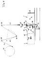
- Gap 14 Below that formed between the two conveyor lines 11 and 13 Gap 14 begins a channel 46 leading downwards, the arc-shaped forward, in the conveying direction 9, bent is, extends over the entire width of the gap 14 and gradually narrows towards the front.
- Channel 46 is on one Traverse 47 arranged, which limits the gap 14 towards the front.
- a flap 48 On the traverse 47 is a flap 48 by means of a Joint 49 mounted with a horizontal, transverse axis C.
- the flap 48 is connected to the frame 10 by an actuator 50 connected; thereby it is from a rest position in which it lies in the plane of the second conveyor section 13, in a pressing position pivotable, in which it vertically from the hinge 49 protrudes above.
- the web 2 can be dispensed with by the driver 38 and This can already be in its lower position together with web guide 39 8 have reached when the drive rollers 34 and 35th start conveying the web down.
- the web 2 from the drive rollers 34 and 35 as far down promoted that they pass through the gap 14 into the channel 46th occurs while the driver 38 back up into his Rest position is moved.
- the Slider 12 moves to the left so that it moves the cuboid 1 forward pushes. Its front 3 consequently presses against the vertically depending section of the web 2, this being itself first to the front 3 and then to the top 4 as well simultaneously applies to the underside 5 of the cuboid 1, while this is pushed over the gap 14 according to FIG.
- the lower section of the web 2 slides horizontally lying flap 48 which has a certain frictional resistance exercised on the web.
- the drive rollers 34 and 35 are during the forward movement of the cuboid 1 shown in FIG. 10 is ineffective; however, the dancer 29 acts as a brake on the web 2. As a result the web 2 is taut over the top 4 and pulled over the bottom 5.
Landscapes
- Engineering & Computer Science (AREA)
- Mechanical Engineering (AREA)
- Basic Packing Technique (AREA)
- Collation Of Sheets And Webs (AREA)
Description
- Fig.1
- eine Seitenansicht einer erfindungsgemäßen Vorrichtung,
- Fig.2
- die Stirnansicht in Richtung des Pfeils II in Fig.1,
- Fig.3
- den senkrechten Schnitt III-III in Fig.1,
- Fig.4
- einen vergrößerten Ausschnitt aus Fig.1,
- Fig.5
- die Ansicht in Richtung des Pfeils V in Fig.4,
- Fig.6
- einen weiter vergrößerten Ausschnitt aus Fig.4 und
- Fig.7 bis 12
- sechs aufeinanderfolgende Zustände innerhalb eines Maschinenzyklus.
Claims (6)
- Verfahren zum Umwickeln von Quadern (1), insbesondere Isolierstoffballen, mit einer Bahn (2) aus Einwickelmaterial, insbesondere Papier, bei demdie Bahn (2) von einem Vorrat in einer Länge abgezogen wird, die dem von einer Vorderseite (3), Rückseite (6), Oberseite (4) und Unterseite (5) gebildeten Umfang eines Quaders (1) zuzüglich einer Überlappung (7) entspricht,die Bahn (2) oberhalb der Ebene der Oberseite (4) des Quaders (1) aufgehängt wird und unterhalb der Ebene der Unterseite (5) des Quaders (1) ein erstes Bahnende bildet,der Quader (1) mit seiner Vorderseite (3) gegen die aufgehängte Bahn (2) bewegt und in einem ungefähr rechten Winkel zu dieser weiterbewegt wird, wobei sich die Bahn (2) auch an die Oberseite (4) und die Unterseite (5) des Quaders (1) anlegt,ein zweites noch mit dem Vorrat verbundenes Bahnende von der Oberseite (4) des Quaders (1) aus an dessen Rückseite (6) angelegt wird unddie Bahnenden übereinandergelegt und miteinander verbunden werden,
dadurch gekennzeichnet, daßdas erste Bahnende gleitend geführt und an der Rückseite (6) des Quaders (1) nach oben geklappt wird, unddas zweite Bahnende im Verlauf seiner Abwärtsbewegung entlang der Rückseite (6) des Quaders (1) vom Vorrat abgetrennt und dort mit dem nach oben geklappten ersten Bahnende verbunden, insbesondere verklebt, wird. - Verfahren nach Anspruch 1,
dadurch gekennzeichnet, daß der Quader (1) festgeklemmt wird, während die Bahnenden an seine Rückseite (6) angelegt und dort miteinander verbunden werden. - Vorrichtung zum Umwickeln von Quadern (1), insbesondere Isolierstoffballen, mit einer Bahn (2) aus Einwickelmaterial, insbesondere Papier, miteiner ersten und einer zweiten ungefähr waagerechten Förderstrecke (11,13), zwischen denen ein querliegender Spalt (14) freigelassen ist, über den die Quader (1) hinwegbewegbar sind,einem Magazin (23), in dem die Bahn (2) vorrätig gehalten wird,einer Umlenkung (33), über welche die Bahn (2) abziehbar ist, um dann ungefähr senkrecht durch den Spalt (14) hindurchbewegt zu werden, undeinem Mitnehmer (38), der zum Erfassen der Bahn (2) ausgebildet und mindestens zweiachsig steuerbar ist, so daß er nach der Bewegung des Quaders (1) über den Spalt (14) hinweg, anschließend an das Anlegen der Bahn (2) an die Oberseite (4) des Quaders (1), gegen die Rückseite (6) des Quaders (1) drückbar ist,
dadurch gekennzeichnet, daß am Anfang der zweiten Förderstrecke (13) eine Klappe (48) gelagert ist, die eine Auflage für den unteren Teil der vom Quader (1) bei seiner Vorwärtsbewegung mitgenommenen Bahn (2) bildet und hinter dem Quader (1) aufwärts bewegbar ist, um das untere Ende der Bahn (2) in einer für den Mitnehmer (38) zum Herstellen der Überlappung (7) erreichbaren Höhe an die Rückseite (6) des Quaders (1) anzulegen. - Vorrichtung nach Anspruch 3,
dadurch gekennzeichnet, daß der Mitnehmer (38) am unteren Rand einer kufenartigen Bahnführung (39) angeordnet ist, die um eine zum Spalt (14) parallele waagerechte Achse (A) schwenkbar an einem Lenker (41) angeordnet ist, der um eine weitere, zum Spalt (14) parallele waagerechte Achse (B) schwenkbar ist. - Vorrichtung nach einem der Ansprüche 2 bis 4,
dadurch gekennzeichnet, daß oberhalb des Spalts (14) ein Paar Antriebswalzen (34,35) angeordnet ist, zwischen denen die Bahn (2) hindurchbewegbar ist. - Vorrichtung nach Anspruch 5,
dadurch gekennzeichnet, daß ebenfalls oberhalb des Spalts (14), jedoch unterhalb der Antriebswalzen (34,35) eine Trennvorrichtung (37) zum Abtrennen der von oben her an die Rückseite (6) des Quaders (1) angelegten Bahn (2) angeordnet ist.
Applications Claiming Priority (2)
| Application Number | Priority Date | Filing Date | Title |
|---|---|---|---|
| DE4416540 | 1994-05-10 | ||
| DE4416540A DE4416540C1 (de) | 1994-05-10 | 1994-05-10 | Verfahren und Vorrichtung zum Umwickeln von Quadern, insbesondere Isolierstoffballen, mit Einwickelmaterial |
Publications (2)
| Publication Number | Publication Date |
|---|---|
| EP0681957A1 EP0681957A1 (de) | 1995-11-15 |
| EP0681957B1 true EP0681957B1 (de) | 1998-06-03 |
Family
ID=6517813
Family Applications (1)
| Application Number | Title | Priority Date | Filing Date |
|---|---|---|---|
| EP95104388A Expired - Lifetime EP0681957B1 (de) | 1994-05-10 | 1995-03-24 | Verfahren und Vorrichtung zum Umwickeln von Quadern, insbesondere Isolierstoffballen, mit Einwickelmaterial |
Country Status (2)
| Country | Link |
|---|---|
| EP (1) | EP0681957B1 (de) |
| DE (2) | DE4416540C1 (de) |
Families Citing this family (3)
| Publication number | Priority date | Publication date | Assignee | Title |
|---|---|---|---|---|
| DE29515605U1 (de) * | 1995-09-30 | 1995-12-14 | Colsman & Kirschner GmbH & Co KG, 45277 Essen | Verpackungsautomat mit automatischem Wechsel des Verpackungsmaterials |
| IT1320919B1 (it) * | 2000-03-14 | 2003-12-10 | Resta Srl | Macchina confezionatrice di materassi in un foglio svolto in continuoda una bobina. |
| CN116461767B (zh) * | 2023-06-05 | 2023-10-03 | 山东大宏智能设备股份有限公司 | 一种垃圾自动六面包装设备 |
Family Cites Families (6)
| Publication number | Priority date | Publication date | Assignee | Title |
|---|---|---|---|---|
| DE1170859B (de) * | 1961-03-07 | 1964-05-21 | Hesser Ag Maschf | Vorrichtung an Einwickelmaschinen zum Umlegen von Einwicklerzuschnitten um blockfoermige Gegenstaende |
| US3238697A (en) * | 1962-10-26 | 1966-03-08 | Gen Strapping Company | Bundle wrapping apparatus |
| US3372526A (en) * | 1965-01-22 | 1968-03-12 | Scandia Packaging Mach | Wrapping mechanism |
| DE1299548B (de) * | 1966-04-16 | 1969-07-17 | Bauer Eberhard | Maschine zum Umhuellen von Gegenstaenden mit Kunststoff-Folie |
| DE2450373A1 (de) * | 1974-10-23 | 1976-04-29 | Bauer Eberhard | Maschine zum umhuellen von gegenstaenden mit kunststoff-folie |
| FR2565201A1 (fr) * | 1984-05-30 | 1985-12-06 | Ouest Conditionnement Delapier | Procede et installation pour l'emballage d'un paquet a l'aide d'une feuille d'emballage et les paquets emballes obtenus |
-
1994
- 1994-05-10 DE DE4416540A patent/DE4416540C1/de not_active Expired - Fee Related
-
1995
- 1995-03-24 EP EP95104388A patent/EP0681957B1/de not_active Expired - Lifetime
- 1995-03-24 DE DE59502388T patent/DE59502388D1/de not_active Expired - Fee Related
Also Published As
| Publication number | Publication date |
|---|---|
| DE4416540C1 (de) | 1995-08-17 |
| DE59502388D1 (de) | 1998-07-09 |
| EP0681957A1 (de) | 1995-11-15 |
Similar Documents
| Publication | Publication Date | Title |
|---|---|---|
| EP0050860B1 (de) | Vorrichtung zum Bilden und Stapeln von von einer Folienschlauchbahn abgetrennten Abschnitten | |
| DE3143063C2 (de) | ||
| EP1808374B1 (de) | Folien- Verpackungsmaschine für Packgutstücke wechselnder Grösse | |
| DE3723601C2 (de) | ||
| DE1561966A1 (de) | Verfahren und Vorrichtung zum Verpacken von Waren | |
| DE3038058A1 (de) | Einrichtung zum aufstapeln von flachen gegenstaenden,insbesondere von faltschachtel-zuschnitten | |
| DE2101116C3 (de) | Stoß-Spleißvorrichtung zum Stoß-an Stoß-Verbinden von Bahnen | |
| DE2038959C3 (de) | Beutelherstellungsmaschine | |
| EP0111210A1 (de) | Vorrichtung zum Umhüllen von Gegenständen mit einer Folie aus Kunststoff oder dergl. | |
| DE3301852A1 (de) | Verfahren und vorrichtung zum verarbeiten von zwei jeweils durch flaechige erzeugnisse, vorzugsweise druckprodukte, gebildeten formationen | |
| DE3300068A1 (de) | Verfahren und maschine zum verpacken eines komprimierbaren stapels, insbesondere von druckschriften | |
| DE102020106025A1 (de) | Verpackungsmaschine und Verfahren zum Verpacken eines Packguts mit einer aus einer oberen Papierbahn und einer unteren Papierbahn erzeugten Umverpackung | |
| EP0681957B1 (de) | Verfahren und Vorrichtung zum Umwickeln von Quadern, insbesondere Isolierstoffballen, mit Einwickelmaterial | |
| DE69713371T2 (de) | Vorrichtung zum miteinanderverbinden von flachen gegenständen | |
| DE4127854A1 (de) | Vorrichtung zum zufuehren von plattenfoermigen zuschnitten zu einer tiefziehmaschine | |
| DE3203644C2 (de) | Vorrichtung zum automatischen Verbinden von Folienbahnen | |
| DE3239378A1 (de) | Zwischenprodukt einer rollen-packmaschine | |
| EP0506645B1 (de) | Vorrichtung zum Herstellen von Taschen für Batterieplatten | |
| DE2024150A1 (de) | Bogen Geradleger | |
| WO2002010021A2 (de) | Verfahren und vorrichtung zum verpacken eines blockes aud einem komprimierbaren material sowie verpackter block | |
| AT412134B (de) | Verfahren und vorrichtung zum eintaschen von batterieplatten | |
| WO2009121542A1 (de) | Vorrichtung und verfahren zur herstellung von säcken aus schlauchstücken | |
| EP0114200B1 (de) | Einrichtung zum Verbinden des ablaufenden Endes eines zu einer Bobine aufgewickelten Bandes mit dem Bandanfang einer neuen Bobine | |
| DE19753870B4 (de) | Verfahren und Vorrichtung zum Verbinden des Endes einer ersten Materialbahn mit dem Anfang einer zweiten Materialbahn | |
| DE19735418A1 (de) | Verfahren und Vorrichtung zur Zuführung einer Hüllstoffbahn zu einer Schlauchbeutel-Verpackungsmaschine |
Legal Events
| Date | Code | Title | Description |
|---|---|---|---|
| PUAI | Public reference made under article 153(3) epc to a published international application that has entered the european phase |
Free format text: ORIGINAL CODE: 0009012 |
|
| AK | Designated contracting states |
Kind code of ref document: A1 Designated state(s): DE FR GB IT SE |
|
| 17P | Request for examination filed |
Effective date: 19951205 |
|
| 17Q | First examination report despatched |
Effective date: 19970115 |
|
| GRAG | Despatch of communication of intention to grant |
Free format text: ORIGINAL CODE: EPIDOS AGRA |
|
| GRAG | Despatch of communication of intention to grant |
Free format text: ORIGINAL CODE: EPIDOS AGRA |
|
| GRAH | Despatch of communication of intention to grant a patent |
Free format text: ORIGINAL CODE: EPIDOS IGRA |
|
| GRAH | Despatch of communication of intention to grant a patent |
Free format text: ORIGINAL CODE: EPIDOS IGRA |
|
| GRAA | (expected) grant |
Free format text: ORIGINAL CODE: 0009210 |
|
| ITF | It: translation for a ep patent filed | ||
| AK | Designated contracting states |
Kind code of ref document: B1 Designated state(s): DE FR GB IT SE |
|
| REF | Corresponds to: |
Ref document number: 59502388 Country of ref document: DE Date of ref document: 19980709 |
|
| GBT | Gb: translation of ep patent filed (gb section 77(6)(a)/1977) |
Effective date: 19980728 |
|
| ET | Fr: translation filed | ||
| PLBE | No opposition filed within time limit |
Free format text: ORIGINAL CODE: 0009261 |
|
| STAA | Information on the status of an ep patent application or granted ep patent |
Free format text: STATUS: NO OPPOSITION FILED WITHIN TIME LIMIT |
|
| 26N | No opposition filed | ||
| PGFP | Annual fee paid to national office [announced via postgrant information from national office to epo] |
Ref country code: FR Payment date: 20010131 Year of fee payment: 7 |
|
| PGFP | Annual fee paid to national office [announced via postgrant information from national office to epo] |
Ref country code: GB Payment date: 20010201 Year of fee payment: 7 |
|
| PGFP | Annual fee paid to national office [announced via postgrant information from national office to epo] |
Ref country code: SE Payment date: 20010323 Year of fee payment: 7 Ref country code: DE Payment date: 20010323 Year of fee payment: 7 |
|
| REG | Reference to a national code |
Ref country code: GB Ref legal event code: IF02 |
|
| PG25 | Lapsed in a contracting state [announced via postgrant information from national office to epo] |
Ref country code: GB Free format text: LAPSE BECAUSE OF NON-PAYMENT OF DUE FEES Effective date: 20020324 |
|
| PG25 | Lapsed in a contracting state [announced via postgrant information from national office to epo] |
Ref country code: SE Free format text: LAPSE BECAUSE OF NON-PAYMENT OF DUE FEES Effective date: 20020325 |
|
| PG25 | Lapsed in a contracting state [announced via postgrant information from national office to epo] |
Ref country code: DE Free format text: LAPSE BECAUSE OF NON-PAYMENT OF DUE FEES Effective date: 20021001 |
|
| EUG | Se: european patent has lapsed |
Ref document number: 95104388.4 |
|
| GBPC | Gb: european patent ceased through non-payment of renewal fee |
Effective date: 20020324 |
|
| PG25 | Lapsed in a contracting state [announced via postgrant information from national office to epo] |
Ref country code: FR Free format text: LAPSE BECAUSE OF NON-PAYMENT OF DUE FEES Effective date: 20021129 |
|
| REG | Reference to a national code |
Ref country code: FR Ref legal event code: ST |
|
| PG25 | Lapsed in a contracting state [announced via postgrant information from national office to epo] |
Ref country code: IT Free format text: LAPSE BECAUSE OF NON-PAYMENT OF DUE FEES;WARNING: LAPSES OF ITALIAN PATENTS WITH EFFECTIVE DATE BEFORE 2007 MAY HAVE OCCURRED AT ANY TIME BEFORE 2007. THE CORRECT EFFECTIVE DATE MAY BE DIFFERENT FROM THE ONE RECORDED. Effective date: 20050324 |