EP0681972A1 - Dispositif pour collecter des déchets, notamment dans des hôpitaux - Google Patents
Dispositif pour collecter des déchets, notamment dans des hôpitaux Download PDFInfo
- Publication number
- EP0681972A1 EP0681972A1 EP95250106A EP95250106A EP0681972A1 EP 0681972 A1 EP0681972 A1 EP 0681972A1 EP 95250106 A EP95250106 A EP 95250106A EP 95250106 A EP95250106 A EP 95250106A EP 0681972 A1 EP0681972 A1 EP 0681972A1
- Authority
- EP
- European Patent Office
- Prior art keywords
- container
- holding device
- cover
- suspended
- stop
- Prior art date
- Legal status (The legal status is an assumption and is not a legal conclusion. Google has not performed a legal analysis and makes no representation as to the accuracy of the status listed.)
- Granted
Links
Images


Classifications
-
- B—PERFORMING OPERATIONS; TRANSPORTING
- B65—CONVEYING; PACKING; STORING; HANDLING THIN OR FILAMENTARY MATERIAL
- B65F—GATHERING OR REMOVAL OF DOMESTIC OR LIKE REFUSE
- B65F1/00—Refuse receptacles; Accessories therefor
- B65F1/0033—Refuse receptacles; Accessories therefor specially adapted for segregated refuse collecting, e.g. receptacles with several compartments; Combination of receptacles
- B65F1/0053—Combination of several receptacles
- B65F1/0066—Rigid receptacles fixed on racks or posts
-
- B—PERFORMING OPERATIONS; TRANSPORTING
- B65—CONVEYING; PACKING; STORING; HANDLING THIN OR FILAMENTARY MATERIAL
- B65F—GATHERING OR REMOVAL OF DOMESTIC OR LIKE REFUSE
- B65F1/00—Refuse receptacles; Accessories therefor
- B65F1/14—Other constructional features; Accessories
- B65F1/141—Supports, racks, stands, posts or the like for holding refuse receptacles
- B65F1/1421—Supports, racks, stands, posts or the like for holding refuse receptacles having means for operating lids or covers
Definitions
- the invention relates to a device for collecting waste according to the preamble of the main claim and the independent claim.
- the object of the invention is therefore to provide a device for collecting waste, in which, while maintaining the ground clearance, the hanging of an empty and the removal of a full container is improved and user-friendly use is ensured.
- a device is provided with a lid that closes the container and opens and closes without problems without manual operation.
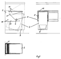
- the 1 shows a holding device 1, which is fastened, for example, to a wall below a work surface and has two forwardly projecting supports 22, into which a container 2 is suspended.
- the container is on the side below its upper edge 2 each provided with a support 3, the respective support surface 14 of which extends to the upper container edge at an angle of approximately 20 °, so that the filling opening is inclined forward for easier filling.
- the position of the support surface 14 is chosen so that the suspended container 2 maintains the intended inclination both empty and at different filling levels.
- the container 2 has a taper 15 or beveled edges, which facilitates the insertion of the container 2 into the holding device 1.
- the inclined support surface 14 is followed by a rounding 16 of the support 3 directed towards the upper edge of the container 2, which makes it easier to put the container 2 on and push it in.
- the holding device 1 has a cross bar 4 between the two supports 22, which serves as a stop.
- Fig. 2 shows two further versions of the carrier system for the fixed suspension of one or more containers 2, which consists of a modular plug-in system.
- a wall bracket 23 is provided, which is designed as a horizontally arranged rail or tube, which has vertical slots 24 made in a grid dimension in two rows one above the other.
- Support arms 22, which are provided with hook and guide elements 25, are to be positively suspended in the slots 24.
- the slot sequence enables the carrier spacing to be adapted to containers of different widths, as shown in FIG. 2a.
- projections 26 are attached instead of a cross bar, which also serve as a stop.
- the support arms have 4 holes with or without threads, in which one or more rods for a container assembly to be attached.
- 2b shows a further embodiment of the support system, in which the slots 27 in the wall support 23 are arranged horizontally in two rows one above the other.
- the support arms 22 are provided with laterally horizontally projecting hook elements 28 which are to be hooked into slots 27.
- FIG. 3 shows a further exemplary embodiment of a holding device 5, the corresponding supports preferably having a circular recess 6 in the front region, in which the container 2 is movably suspended with supports 7 formed on it laterally in the central region and formed as circular projections.
- the center of gravity of the suspended container 2 is selected such that the empty container or container filled to different heights tilts backwards, again with a stop 8 against which it bears.
- a lid 11 closes the filling opening of the container 2.
- the container has a web at its lower front area with which the container 2 is inclined forward by foot actuation, the lid being pivoted due to the pivoting movement of the rear edge of the container 2 11 lifts.
- the holding device 5 is in turn provided with a stop designed as a crossbar 10, which limits the inclination of the container when the foot is actuated.
- Fig. 4 shows the container 2 with the features already described. He also shows handle openings 17, 18, which facilitate the insertion and removal into or from the holding devices 1 and 5 and the carrying of the container 2.
- a recessed grip 19 is also provided in the area of the bottom, which facilitates the emptying of a container.
- the front edge of the container has a writing field 20.
- a stacking edge 21 is provided, by means of which several containers 2 can be securely stacked, for example during transport.
- the height and depth of the container 2 are chosen so that they can be used under the usual work surfaces, taking into account their inclination and sufficient opening for filling with waste or valuable materials.
- the width of the container 2 is variable. For the rest, reference is expressly made to the drawing with regard to the designs of the container and the holding device.
- the empty container can be used ergonomically and pushed as far as the stop 4.
- the container When the container is released, it automatically assumes the inclined position.
- the filled container When it is removed, the filled container is brought into an ergonomically favorable position via the curve 16 and pulled out towards the front. Since the container has only a small contact surface, it is easier to pull it out.
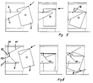
- Fig. 6 shows the sequence when inserting the container 2 in the holding device 5.
- the lid 11 is extended rearwardly with respect to its pivot point 24 and has a counterweight in the rear area, so that it is initially raised.
- the design of the carrier 23 and the container taper 15 enables an ergonomically favorable insertion and positioning of the container in the recess 6.
- the container 2 swivels into the normal position and closes the lid 11 via a stop 13 directed downward on the lid, which is supported by the rear edge of the container is operated. If the container 2 is pressed backwards on the web 9 with the foot, the lid opens and the container opening tilts forwardly downward into a position which is favorable for filling. To remove the filled container is pulled out of the recess 16 and removed to the front.
- Fig. 7 shows an example of the device built under a worktop between base cabinets made of carrier and container. Here, three units of different widths are added together.
- FIG. 8 shows an example of the fastening of one or more containers 2 on a mobile holding device 1.
- the holding device runs on wheels 29 and a cover or worktop 30 is arranged above the containers 2. This makes it possible to integrate containers for collecting waste into mobile workplaces.
Landscapes
- Engineering & Computer Science (AREA)
- Mechanical Engineering (AREA)
- Refuse Receptacles (AREA)
- Accommodation For Nursing Or Treatment Tables (AREA)
- Electrical Discharge Machining, Electrochemical Machining, And Combined Machining (AREA)
- Filters For Electric Vacuum Cleaners (AREA)
- Processing Of Solid Wastes (AREA)
- Refuse Collection And Transfer (AREA)
Applications Claiming Priority (2)
| Application Number | Priority Date | Filing Date | Title |
|---|---|---|---|
| DE9407310U DE9407310U1 (de) | 1994-05-05 | 1994-05-05 | Vorrichtung zum Sammeln von Abfällen |
| DE9407310U | 1994-05-05 |
Publications (2)
| Publication Number | Publication Date |
|---|---|
| EP0681972A1 true EP0681972A1 (fr) | 1995-11-15 |
| EP0681972B1 EP0681972B1 (fr) | 1999-08-25 |
Family
ID=6908149
Family Applications (1)
| Application Number | Title | Priority Date | Filing Date |
|---|---|---|---|
| EP95250106A Expired - Lifetime EP0681972B1 (fr) | 1994-05-05 | 1995-05-04 | Dispositif pour collecter des déchets, notamment dans des hÔpitaux |
Country Status (3)
| Country | Link |
|---|---|
| EP (1) | EP0681972B1 (fr) |
| AT (1) | ATE183713T1 (fr) |
| DE (2) | DE9407310U1 (fr) |
Families Citing this family (1)
| Publication number | Priority date | Publication date | Assignee | Title |
|---|---|---|---|---|
| DE9407310U1 (de) * | 1994-05-05 | 1994-07-07 | Gelbach, Fritz, 89075 Ulm | Vorrichtung zum Sammeln von Abfällen |
Citations (4)
| Publication number | Priority date | Publication date | Assignee | Title |
|---|---|---|---|---|
| EP0444620A1 (fr) * | 1990-02-26 | 1991-09-04 | Anton Heninger | Unité de ramassage d'ordures |
| DE9113834U1 (de) * | 1991-11-07 | 1992-01-02 | Gelbach, Fritz, 7900 Ulm | Vorrichtung zum gezielten Sammeln von Abfällen |
| DE4101285A1 (de) * | 1991-01-17 | 1992-07-23 | Eckart Roth | Vorrichtung zur entsorgung von abfall |
| DE9407310U1 (de) * | 1994-05-05 | 1994-07-07 | Gelbach, Fritz, 89075 Ulm | Vorrichtung zum Sammeln von Abfällen |
-
1994
- 1994-05-05 DE DE9407310U patent/DE9407310U1/de not_active Expired - Lifetime
-
1995
- 1995-05-04 EP EP95250106A patent/EP0681972B1/fr not_active Expired - Lifetime
- 1995-05-04 DE DE59506662T patent/DE59506662D1/de not_active Expired - Lifetime
- 1995-05-04 AT AT95250106T patent/ATE183713T1/de not_active IP Right Cessation
Patent Citations (4)
| Publication number | Priority date | Publication date | Assignee | Title |
|---|---|---|---|---|
| EP0444620A1 (fr) * | 1990-02-26 | 1991-09-04 | Anton Heninger | Unité de ramassage d'ordures |
| DE4101285A1 (de) * | 1991-01-17 | 1992-07-23 | Eckart Roth | Vorrichtung zur entsorgung von abfall |
| DE9113834U1 (de) * | 1991-11-07 | 1992-01-02 | Gelbach, Fritz, 7900 Ulm | Vorrichtung zum gezielten Sammeln von Abfällen |
| DE9407310U1 (de) * | 1994-05-05 | 1994-07-07 | Gelbach, Fritz, 89075 Ulm | Vorrichtung zum Sammeln von Abfällen |
Also Published As
| Publication number | Publication date |
|---|---|
| DE59506662D1 (de) | 1999-09-30 |
| DE9407310U1 (de) | 1994-07-07 |
| EP0681972B1 (fr) | 1999-08-25 |
| ATE183713T1 (de) | 1999-09-15 |
Similar Documents
| Publication | Publication Date | Title |
|---|---|---|
| DE60109618T2 (de) | Stützanordnung | |
| DE1930475A1 (de) | Karteischublade | |
| DE19935312C2 (de) | Herausziehbarer Geschirrkorb für Geschirrspülmaschinen | |
| DE3300770A1 (de) | Vorrichtung zur fuetterung von tieren | |
| DE19512128C5 (de) | Vorrichtung zum Verstellen der Höhenlage des Geschirrkorbes einer Geschirrspülmaschine | |
| DE212006000092U1 (de) | Sortieranlage | |
| DE4310841A1 (de) | Vorrichtung für getrenntes Sammeln unterschiedlicher Haushaltsabfälle | |
| EP0681972A1 (fr) | Dispositif pour collecter des déchets, notamment dans des hôpitaux | |
| DE2401172A1 (de) | Gewuerzstaender fuer gewuerzstreuer | |
| DE2101015C3 (de) | Vorrichtung zum Entleeren von Behältern, beispielsweise MüUgefäflen | |
| DE3844317C2 (fr) | ||
| DE9113834U1 (de) | Vorrichtung zum gezielten Sammeln von Abfällen | |
| DE2660465C2 (de) | Vorrichtung zum Lagern von Maschinenwerkzeugen | |
| DE202009012961U1 (de) | Sortieranlage | |
| DE202021104950U1 (de) | Käfiganordnung für Nagetiere | |
| DE7817066U1 (de) | Vorrichtung zum entleeren von behaeltern in sammelbehaelter | |
| DE3907599A1 (de) | Tresen, insbesondere fuer bankeinrichtungen | |
| DE9301166U1 (de) | Gepolstertes Sitzmöbel, insbesondere Sofa | |
| DE202016103878U1 (de) | Flüssigkeitsbehälterhalterung sowie System | |
| DE803713C (de) | Setzplatz | |
| DE1654733A1 (de) | Arbeitstisch | |
| DE8808839U1 (de) | Speicher- und Ausgabevorrichtung mit selbsttätiger Höhenregulierung | |
| DE1228194B (de) | Hublader | |
| DE202007006684U1 (de) | Kehrset und Auszugsystem mit einem Kehrset | |
| DE4233177A1 (de) | In einen Schrank, insbesondere Küchenschrank, einbaubarer Behälter, insbesondere Abfall-Sammelbehälter |
Legal Events
| Date | Code | Title | Description |
|---|---|---|---|
| PUAI | Public reference made under article 153(3) epc to a published international application that has entered the european phase |
Free format text: ORIGINAL CODE: 0009012 |
|
| AK | Designated contracting states |
Kind code of ref document: A1 Designated state(s): AT CH DE FR IT LI NL SE |
|
| 17P | Request for examination filed |
Effective date: 19960514 |
|
| 17Q | First examination report despatched |
Effective date: 19970905 |
|
| GRAG | Despatch of communication of intention to grant |
Free format text: ORIGINAL CODE: EPIDOS AGRA |
|
| GRAG | Despatch of communication of intention to grant |
Free format text: ORIGINAL CODE: EPIDOS AGRA |
|
| GRAH | Despatch of communication of intention to grant a patent |
Free format text: ORIGINAL CODE: EPIDOS IGRA |
|
| GRAH | Despatch of communication of intention to grant a patent |
Free format text: ORIGINAL CODE: EPIDOS IGRA |
|
| GRAA | (expected) grant |
Free format text: ORIGINAL CODE: 0009210 |
|
| AK | Designated contracting states |
Kind code of ref document: B1 Designated state(s): AT CH DE FR IT LI NL SE |
|
| PG25 | Lapsed in a contracting state [announced via postgrant information from national office to epo] |
Ref country code: SE Free format text: THE PATENT HAS BEEN ANNULLED BY A DECISION OF A NATIONAL AUTHORITY Effective date: 19990825 |
|
| REF | Corresponds to: |
Ref document number: 183713 Country of ref document: AT Date of ref document: 19990915 Kind code of ref document: T |
|
| REG | Reference to a national code |
Ref country code: CH Ref legal event code: EP |
|
| REF | Corresponds to: |
Ref document number: 59506662 Country of ref document: DE Date of ref document: 19990930 |
|
| ITF | It: translation for a ep patent filed | ||
| REG | Reference to a national code |
Ref country code: CH Ref legal event code: NV Representative=s name: TROESCH SCHEIDEGGER WERNER AG |
|
| ET | Fr: translation filed | ||
| PLBE | No opposition filed within time limit |
Free format text: ORIGINAL CODE: 0009261 |
|
| STAA | Information on the status of an ep patent application or granted ep patent |
Free format text: STATUS: NO OPPOSITION FILED WITHIN TIME LIMIT |
|
| 26N | No opposition filed | ||
| REG | Reference to a national code |
Ref country code: CH Ref legal event code: PUE Owner name: KOLONDRA GMBH TRANSFER- RIEGER GMBH |
|
| NLS | Nl: assignments of ep-patents |
Owner name: RIEGER GMBH |
|
| REG | Reference to a national code |
Ref country code: FR Ref legal event code: TP |
|
| PGFP | Annual fee paid to national office [announced via postgrant information from national office to epo] |
Ref country code: NL Payment date: 20050531 Year of fee payment: 11 Ref country code: FR Payment date: 20050531 Year of fee payment: 11 Ref country code: AT Payment date: 20050531 Year of fee payment: 11 |
|
| PGFP | Annual fee paid to national office [announced via postgrant information from national office to epo] |
Ref country code: CH Payment date: 20050729 Year of fee payment: 11 |
|
| PG25 | Lapsed in a contracting state [announced via postgrant information from national office to epo] |
Ref country code: AT Free format text: LAPSE BECAUSE OF NON-PAYMENT OF DUE FEES Effective date: 20060504 |
|
| PG25 | Lapsed in a contracting state [announced via postgrant information from national office to epo] |
Ref country code: LI Free format text: LAPSE BECAUSE OF NON-PAYMENT OF DUE FEES Effective date: 20060531 Ref country code: CH Free format text: LAPSE BECAUSE OF NON-PAYMENT OF DUE FEES Effective date: 20060531 |
|
| PGFP | Annual fee paid to national office [announced via postgrant information from national office to epo] |
Ref country code: IT Payment date: 20060531 Year of fee payment: 12 |
|
| PG25 | Lapsed in a contracting state [announced via postgrant information from national office to epo] |
Ref country code: NL Free format text: LAPSE BECAUSE OF NON-PAYMENT OF DUE FEES Effective date: 20061201 |
|
| REG | Reference to a national code |
Ref country code: CH Ref legal event code: PL |
|
| NLV4 | Nl: lapsed or anulled due to non-payment of the annual fee |
Effective date: 20061201 |
|
| REG | Reference to a national code |
Ref country code: FR Ref legal event code: ST Effective date: 20070131 |
|
| PG25 | Lapsed in a contracting state [announced via postgrant information from national office to epo] |
Ref country code: FR Free format text: LAPSE BECAUSE OF NON-PAYMENT OF DUE FEES Effective date: 20060531 |
|
| PG25 | Lapsed in a contracting state [announced via postgrant information from national office to epo] |
Ref country code: IT Free format text: LAPSE BECAUSE OF NON-PAYMENT OF DUE FEES Effective date: 20070504 |
|
| PGFP | Annual fee paid to national office [announced via postgrant information from national office to epo] |
Ref country code: DE Payment date: 20130731 Year of fee payment: 19 |
|
| REG | Reference to a national code |
Ref country code: DE Ref legal event code: R119 Ref document number: 59506662 Country of ref document: DE |
|
| REG | Reference to a national code |
Ref country code: DE Ref legal event code: R119 Ref document number: 59506662 Country of ref document: DE Effective date: 20141202 |
|
| PG25 | Lapsed in a contracting state [announced via postgrant information from national office to epo] |
Ref country code: DE Free format text: LAPSE BECAUSE OF NON-PAYMENT OF DUE FEES Effective date: 20141202 |