EP0681996A1 - Verfahren zum Herstellen von komplexen Kompositplatten durch multiaxial isostatisches Pressen, Werkzeuge dafür und Strukturen so erhalten - Google Patents
Verfahren zum Herstellen von komplexen Kompositplatten durch multiaxial isostatisches Pressen, Werkzeuge dafür und Strukturen so erhalten Download PDFInfo
- Publication number
- EP0681996A1 EP0681996A1 EP95450005A EP95450005A EP0681996A1 EP 0681996 A1 EP0681996 A1 EP 0681996A1 EP 95450005 A EP95450005 A EP 95450005A EP 95450005 A EP95450005 A EP 95450005A EP 0681996 A1 EP0681996 A1 EP 0681996A1
- Authority
- EP
- European Patent Office
- Prior art keywords
- mold
- deformable
- temperature
- parts
- pressure
- Prior art date
- Legal status (The legal status is an assumption and is not a legal conclusion. Google has not performed a legal analysis and makes no representation as to the accuracy of the status listed.)
- Granted
Links
- 238000000034 method Methods 0.000 title claims abstract description 24
- 239000002131 composite material Substances 0.000 title claims abstract description 14
- 238000000462 isostatic pressing Methods 0.000 title description 3
- 239000000919 ceramic Substances 0.000 claims abstract description 8
- 238000004017 vitrification Methods 0.000 claims abstract description 7
- 239000011347 resin Substances 0.000 claims abstract description 5
- 229920005989 resin Polymers 0.000 claims abstract description 5
- 230000000295 complement effect Effects 0.000 claims abstract description 4
- 239000000835 fiber Substances 0.000 claims description 20
- 238000003825 pressing Methods 0.000 claims description 12
- 229910052751 metal Inorganic materials 0.000 claims description 11
- 239000002184 metal Substances 0.000 claims description 11
- 238000000197 pyrolysis Methods 0.000 claims description 10
- 238000005056 compaction Methods 0.000 claims description 7
- 238000002468 ceramisation Methods 0.000 claims description 5
- 239000011230 binding agent Substances 0.000 claims description 3
- 238000003466 welding Methods 0.000 claims description 2
- 229910000831 Steel Inorganic materials 0.000 abstract 1
- 230000003287 optical effect Effects 0.000 abstract 1
- 239000010959 steel Substances 0.000 abstract 1
- 239000004744 fabric Substances 0.000 description 10
- 239000011521 glass Substances 0.000 description 8
- 239000011159 matrix material Substances 0.000 description 8
- 230000003014 reinforcing effect Effects 0.000 description 8
- 238000004519 manufacturing process Methods 0.000 description 7
- VYPSYNLAJGMNEJ-UHFFFAOYSA-N Silicium dioxide Chemical compound O=[Si]=O VYPSYNLAJGMNEJ-UHFFFAOYSA-N 0.000 description 6
- OKTJSMMVPCPJKN-UHFFFAOYSA-N Carbon Chemical compound [C] OKTJSMMVPCPJKN-UHFFFAOYSA-N 0.000 description 3
- 239000010410 layer Substances 0.000 description 3
- 239000000843 powder Substances 0.000 description 3
- 239000000377 silicon dioxide Substances 0.000 description 3
- 101100334009 Caenorhabditis elegans rib-2 gene Proteins 0.000 description 2
- 229910000287 alkaline earth metal oxide Inorganic materials 0.000 description 2
- 239000011324 bead Substances 0.000 description 2
- 229910052799 carbon Inorganic materials 0.000 description 2
- HBMJWWWQQXIZIP-UHFFFAOYSA-N silicon carbide Chemical compound [Si+]#[C-] HBMJWWWQQXIZIP-UHFFFAOYSA-N 0.000 description 2
- 229910010271 silicon carbide Inorganic materials 0.000 description 2
- 238000003826 uniaxial pressing Methods 0.000 description 2
- 229910001182 Mo alloy Inorganic materials 0.000 description 1
- -1 Z r O2 Inorganic materials 0.000 description 1
- 239000003513 alkali Substances 0.000 description 1
- PNEYBMLMFCGWSK-UHFFFAOYSA-N aluminium oxide Inorganic materials [O-2].[O-2].[O-2].[Al+3].[Al+3] PNEYBMLMFCGWSK-UHFFFAOYSA-N 0.000 description 1
- 229910052681 coesite Inorganic materials 0.000 description 1
- 230000006835 compression Effects 0.000 description 1
- 238000007906 compression Methods 0.000 description 1
- 229910052593 corundum Inorganic materials 0.000 description 1
- 229910052906 cristobalite Inorganic materials 0.000 description 1
- 238000000280 densification Methods 0.000 description 1
- 239000003365 glass fiber Substances 0.000 description 1
- 239000002241 glass-ceramic Substances 0.000 description 1
- 229910001026 inconel Inorganic materials 0.000 description 1
- 238000003780 insertion Methods 0.000 description 1
- 230000037431 insertion Effects 0.000 description 1
- 238000005304 joining Methods 0.000 description 1
- 238000003754 machining Methods 0.000 description 1
- 239000000463 material Substances 0.000 description 1
- 238000002844 melting Methods 0.000 description 1
- 230000008018 melting Effects 0.000 description 1
- 239000007769 metal material Substances 0.000 description 1
- 238000005192 partition Methods 0.000 description 1
- 238000007747 plating Methods 0.000 description 1
- 230000002787 reinforcement Effects 0.000 description 1
- 235000012239 silicon dioxide Nutrition 0.000 description 1
- 239000002356 single layer Substances 0.000 description 1
- 229910000679 solder Inorganic materials 0.000 description 1
- 239000010935 stainless steel Substances 0.000 description 1
- 229910001220 stainless steel Inorganic materials 0.000 description 1
- 229910052682 stishovite Inorganic materials 0.000 description 1
- 230000008646 thermal stress Effects 0.000 description 1
- 229910052905 tridymite Inorganic materials 0.000 description 1
- 230000037303 wrinkles Effects 0.000 description 1
- 229910001845 yogo sapphire Inorganic materials 0.000 description 1
Images



Classifications
-
- C—CHEMISTRY; METALLURGY
- C03—GLASS; MINERAL OR SLAG WOOL
- C03B—MANUFACTURE, SHAPING, OR SUPPLEMENTARY PROCESSES
- C03B11/00—Pressing molten glass or performed glass reheated to equivalent low viscosity without blowing
- C03B11/14—Pressing laminated glass articles or glass with metal inserts or enclosures, e.g. wires, bubbles, coloured parts
-
- C—CHEMISTRY; METALLURGY
- C03—GLASS; MINERAL OR SLAG WOOL
- C03B—MANUFACTURE, SHAPING, OR SUPPLEMENTARY PROCESSES
- C03B19/00—Other methods of shaping glass
- C03B19/06—Other methods of shaping glass by sintering, e.g. by cold isostatic pressing of powders and subsequent sintering, by hot pressing of powders, by sintering slurries or dispersions not undergoing a liquid phase reaction
-
- C—CHEMISTRY; METALLURGY
- C03—GLASS; MINERAL OR SLAG WOOL
- C03B—MANUFACTURE, SHAPING, OR SUPPLEMENTARY PROCESSES
- C03B37/00—Manufacture or treatment of flakes, fibres, or filaments from softened glass, minerals, or slags
- C03B37/10—Non-chemical treatment
- C03B37/14—Re-forming fibres or filaments, i.e. changing their shape
- C03B37/15—Re-forming fibres or filaments, i.e. changing their shape with heat application, e.g. for making optical fibres
Definitions
- the present invention relates to complex sheet metal work in composite material and more specifically to the production of one-piece structures or parts formed from one or more parts of relatively thin thickness, curved and / or planar and capable of forming various right angles between them. or not, the wall of said parts being formed of one or more layers of fibers embedded in a vitreous or vitro-ceramic matrix.
- the composite structures thus obtained are capable of withstanding very high mechanical and thermal stresses.
- the present invention aims precisely to propose a technique in particular suitable for such complex structures.
- said part of relatively thin thickness is draped over the rigid element of the mold, then the rib or ribs are then placed, also by draping , the deformable element is placed on the rigid element, which consists of a thin sheet shaped to match the rib (s), then said pressing operations are carried out at high pressure and temperature.
- a draping is carried out for each compartment on a thin deformable support constituting a part of the deformable element of the complex mold, then the draped supports are placed side by side and they are assembled in line with their non-draped parts with said rigid element of the mold, and said pressing operations are carried out at high pressure and temperature.
- the two elements of the complex mold are advantageously metallic and the deformable element is preferably a thin sheet.
- the plating under very high pressure by such a metal sheet of the preform on the rigid non-deformable part of the mold guarantees excellent regularity, both in terms of the surface flatness of the parts of the part and their thickness which can thus be perfectly mastered.
- the lay-up to obtain the pre-form can be carried out from fabric elements of prepreg fibers which have already undergone compaction as well as pyrolysis. But, advantageously, one can start from non-pyrolized fabrics.
- the interior of the mold is connected to a vacuum source allowing not only the pyrolysis of the prepreg fibers with evacuation of the resin binders, but possibly the prior compaction of said fabrics, if such compaction had not already been operated on.
- All of the compacting, pyrolysis and pressing operations at high temperature and pressure can advantageously be carried out in an isostatic press at high temperature and high pressure, hereinafter called hyperclave, capable of producing vacuum.
- the fibers which can be used in accordance with the invention are, for example, glass, silica, carbon, SiCO, SiCN, ceramic fibers, or the like.
- the vitreous or vitro-ceramic matrix may consist, for example, of at least one oxide of the SiO2, Al2O3, Z r O2, B2O3 type, or of alkali or alkaline earth oxides.
- the preform consists of one or more layers of long or short fibers, arranged according to structures of all types, for example fabrics, mats, wicks, felts, etc.
- the fibers used to constitute a preform are fabrics of SiC fibers preimpregnated with glass.
- the invention also relates to special tools for implementing the method of the invention, namely said complex mold in two parts, rigid and deformable.
- the invention thus makes it possible to produce structures in complex composite material and in particular structures with reinforcing ribs or with compartments, open or closed and with walls densified according to thicknesses and compression rates. Pre-determined, of remarkable resistance mechanically and in temperature, quickly, precisely, safely and using tools which can be almost entirely reusable.
- Figure 1 typically shows a part 1 of composite material achievable using the method of the invention.
- This part 1 is cylindrical, of relatively thin wall and is internally provided with a reinforcing rib 2 constituted by an annular part with T section attached to the internal face of the part.
- the two parts 1 and 2 are made from draped fibers, for example fabric of silicon carbide fibers pre-impregnated with glass, arranged in several layers until the desired thickness is obtained.
- FIG. 2 we will now refer to FIG. 2 to describe an embodiment of the method of the invention suitable for making a part of the type of FIG. 1.
- a complex mold comprising a rigid, non-deformable element or part and a deformable element, the two elements being assembled so as to trap a pre-form of the part, produced by draping, and which will be, at during an isostatic pressing at high pressure and high temperature, pressed by the deformable element of the mold against the non-deformable element, the internal faces of the mold in contact with the preform being of course shaped or adapted to the type of part to be achieve.
- FIG. 2 there is shown at 3 a cylindrical sleeve having a thick wall, of ten millimeters for example, of a suitable metallic material, such as a molybdenum alloy for high temperatures, of "Inconel “or stainless steel, depending on the melting temperature of the glass of the matrix of the composite material.
- a suitable metallic material such as a molybdenum alloy for high temperatures, of "Inconel "or stainless steel, depending on the melting temperature of the glass of the matrix of the composite material.
- annular part 4 is made of the same material as the sleeve 3, the internal end of which is bevelled at 5.
- the sleeve 3 and the rings 4 constitute the rigid, non-deformable element or part of a complex mold.
- the preform is produced by draping fabric of the type mentioned above, either on an external graphite form (not shown), or directly inside the sleeve 3.
- the assembly is placed under a bladder, in the known manner, in order to carry out compaction for example under a pressure of 1 bar, obtained by placing the bladder under vacuum a temperature of approximately 120 ° C. Then, the bladder is removed and a pyrolysis of the preform on its tools is carried out, always in the known manner, to remove the binders which held the glass powder on the fabrics.
- the pre-form is then removed from the tool and introduced into the cylindrical sleeve 3, one of the rings 4 of which is removed to allow the insertion of said pre-form (6), then reattached to the sleeve 3 for example by a solder 8.
- one of the rings 4 is provided with a vacuum duct 9 communicating, by a hole made in the ring, with the interior space of the mold whose deformable element is formed of an internal thin jacket 10 formed using several parts 10a, 10b, 10c, 10 d, attached and welded to hug all the visible faces of the preform 6.
- the two parts of the mold are then welded at 11.
- the various parts of the internal jacket 10 will compress all the parts opposite the preform 6, including the rib 7.
- the various elements 10a to 10d are shaped and dimensioned as a function of the morphology of the rib 7.
- the vacuum duct 9 makes it possible to carry out the preliminary compacting and pyrolysis operations indicated above, if the latter have not already been done.
- the inner jacket 10 is made of the same metal as the non-deformable part (3,4) of the mold.
- the assembly shown in FIG. 2 is then subjected to isostatic pressing under high pressure and high temperature in a hyperclave.
- the conduit 9 is pinched and welded, then the assembly is placed in the hyperclave.
- the temperature in the hyperclave rose to the softening temperature of the glass powder.
- the pressure necessary to press the thin deformable wall 10 against the preform 6 is exerted in the hyperclave, which allows it to be crushed against the internal wall of the sleeve 3.
- the thickness of the rings 4 is slightly greater than that of the preform 6, these rings, thanks to the bevel 5, avoiding both the pinching of the edges of the preform and the tearing of the thin wall 10 applied against the latter.
- the wall thickness of the preform 6 can thus be reduced, for example, from 6 to 2 mm.
- the temperatures and pressures involved depend on the nature of the vitreous or vitro-ceramic matrix of the composite material and on the nature and size of said internal thin jacket.
- the part 6 is removed from the tooling, after machining of the welding zones (8, 11) and removal of the parts 4 and 10 and the part 6 is machined at its ends to the dimensions of the final piece 1.
- the preform 6 can be produced directly on the internal face of the sleeve 3.
- Parts 4 and 10 are then put in place, the assembly is placed in the hyperclave in order to produce, by evacuating the device, said compacting and pyrolysis, the tube 9 being of course not closed.
- the vitrification or ceramization of the matrix of the composite material is checked as before and the shaped part 6 is removed, then machined to dimensions.
- the tool (3,4) is of course reusable.
- pre-form 6 it is preferable to place the pre-form 6 inside the sleeve 3 rather than outside, because it is better to exert on the fibers of the cylindrical pre-form 6 a centrifugal pressure than a centripetal pressure which would risk cause wrinkles in the tissue.
- Centrifugal expansion of the tissues also has the advantage of stretching the fibers.
- the final part obtained has a densified wall of equal thickness, the degree of densification depending on the value of the pressure created in the hyperclave.
- FIG. 3 represents a profiled, hollow, compartmentalized part, of generally parallelepiped shape.
- prepreg fibers 19 are draped independently on hollow sections 12 to 18 of shape corresponding to the separate compartments 12 'to 18' of the piece of Figure 3.
- the draped sections 12 to 18, suitably placed side by side (FIG. 5), are surrounded on their flanks by a thick non-deformable wall 20 so as to leave free the ends of the sections 12 to 18 which are for example of the same metal than the shirt 10.
- the sections 12 to 18 are thin-walled tubes, open at their two ends and of the same metal as the parts 20.
- a conduit 22 communicates the outside with the interstitial space between the inner face of the envelope 20 and the outer faces of the various profiles.
- the tool of FIG. 5 is used exactly like that of FIG. 2 in a pressure and vacuum hyperclave carrying out both the compaction of the preform formed by all of the drapes 19, the pyrolysis, then the pressing isostatic at high pressure and high temperature.
- FIG. 6 illustrates the position in the mold of the various drapes 19 on their profiles 12 to 18, before compacting and FIG. 7 illustrates these same drapes and profiles at the end of pressing in the hyperclave.
- the conduit 22 is connected to a vacuum source and for the hyperclave pressing the conduit 22 is previously closed.
- the part of FIG. 8 consists of a highly curved panel 23 and provided with internal reinforcement ribs 24.
- Figures 9 and 10 show a tool according to the invention adapted to this part.
- This tool consists of a mold comprising a deformable part consisting of open profiles in the form of curved troughs 25 corresponding to the open compartments formed on the internal face of the panel 23. On the external face of the profiles 25 are draped with fabrics of pre fibers. -impregnated 26.
- the assembly is placed inside a non-deformable part 27 of the mold corresponding to the panel 23.
- the sections 25 are thin-walled and of the same metal as the part 27.
- a conduit 30 connects the outside the internal space occupied by the prepreg fibers.
- the mold of FIG. 10 is used like that of FIG. 5 and in the same manner as that illustrated by FIGS. 6 and 7, the drapes 26 will be pressed against the opposite face of the non-deformable part 27 or against a drapery in look, due to the deformation of the thin parts 25 in the hyperclave.
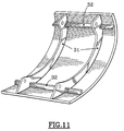
- Figures 12 and 13 illustrate a variant of the tool of Figures 9 and 10 for the production of a part of the type shown in Figure 11 having longitudinal ribs 31 and transverse ribs 32 which require to add, to achieve these transverse ribs , complementary elements 33 in the extension of the profiles 34 intended for the other ribs.
- the opposite ends of the elements and profiles 33, 34 have raised edges 35 to define said transverse ribs 32.
- the elements 33, 34 are draped (36) on their external face and on the external face of the edges 35 and the assembly is placed in a device 37 to 40 corresponding respectively to the device 27 to 30 of FIG. 10.
- FIGS. 6 and 7 represent in 1 'respectively a cylindrical part and a panel, provided internally with reinforcing ribs 44.
- the mold of figure 13 is used in the same way as the mold of figure 10.
- the parts obtained in accordance with the process are so-called "hot" composite parts which can be used continuously at temperatures of the order of 1000 ° C. and retaining at these temperatures high mechanical characteristics.
Landscapes
- Chemical & Material Sciences (AREA)
- Engineering & Computer Science (AREA)
- Manufacturing & Machinery (AREA)
- Materials Engineering (AREA)
- Organic Chemistry (AREA)
- Life Sciences & Earth Sciences (AREA)
- General Life Sciences & Earth Sciences (AREA)
- Geochemistry & Mineralogy (AREA)
- Dispersion Chemistry (AREA)
- Manufacture Of Alloys Or Alloy Compounds (AREA)
- Moulding By Coating Moulds (AREA)
Applications Claiming Priority (2)
| Application Number | Priority Date | Filing Date | Title |
|---|---|---|---|
| FR9405860 | 1994-05-06 | ||
| FR9405860A FR2719577B1 (fr) | 1994-05-06 | 1994-05-06 | Procédé de réalisation de pièces de tôlerie complexes en matériau composite par pressage multiaxial isostatique, outillage pour sa mise en Óoeuvre et structures ainsi obtenues. |
Publications (2)
| Publication Number | Publication Date |
|---|---|
| EP0681996A1 true EP0681996A1 (de) | 1995-11-15 |
| EP0681996B1 EP0681996B1 (de) | 2001-07-25 |
Family
ID=9463157
Family Applications (1)
| Application Number | Title | Priority Date | Filing Date |
|---|---|---|---|
| EP19950450005 Expired - Lifetime EP0681996B1 (de) | 1994-05-06 | 1995-05-03 | Verfahren zum Herstellen von komplexen Kompositplatten durch multiaxial isostatisches Pressen, Werkzeuge dafür und Strukturen so erhalten |
Country Status (3)
| Country | Link |
|---|---|
| EP (1) | EP0681996B1 (de) |
| DE (1) | DE69521834D1 (de) |
| FR (1) | FR2719577B1 (de) |
Citations (8)
| Publication number | Priority date | Publication date | Assignee | Title |
|---|---|---|---|---|
| WO1985004835A1 (en) * | 1984-04-20 | 1985-11-07 | United Technologies Corporation | Method for forming composite articles of complex shapes |
| US4961771A (en) * | 1988-12-27 | 1990-10-09 | United Technologies Corporation | Stress-free composite and a method of and arrangement for manufacturing the same |
| EP0426352A1 (de) * | 1989-10-30 | 1991-05-08 | Corning Incorporated | Verfahren zur Herstellung eines keramischen Matrix-Verbundwerkstoffes |
| US5122176A (en) * | 1990-01-17 | 1992-06-16 | Mcdonnell Douglas Corporation | A method of densifying a glass or glass composite structure |
| EP0501729A1 (de) * | 1991-02-28 | 1992-09-02 | British Aerospace Public Limited Company | Verfahren zur Herstellung eines Glaskeramikkörpers |
| EP0509178A2 (de) * | 1991-04-15 | 1992-10-21 | Corning Incorporated | Verfahren zum Herstellen eines versteiften Paneels aus einer keramischen Kompositmatrix |
| FR2684369A1 (fr) * | 1991-12-03 | 1993-06-04 | Deutsche Forsch Luft Raumfahrt | Procede pour la fabrication de structures renforcees par fibres comportant une matrice en verre. |
| EP0546877A1 (de) * | 1991-11-29 | 1993-06-16 | AEROSPATIALE Société Nationale Industrielle | Verfahren zum Herstellen von komplexen Hohlkörpern durch uniaxiales Heisspressen eines Verbundmaterials mit einer glasartigen Matrix und die so erhaltenen Produkte |
-
1994
- 1994-05-06 FR FR9405860A patent/FR2719577B1/fr not_active Expired - Fee Related
-
1995
- 1995-05-03 DE DE69521834T patent/DE69521834D1/de not_active Expired - Lifetime
- 1995-05-03 EP EP19950450005 patent/EP0681996B1/de not_active Expired - Lifetime
Patent Citations (8)
| Publication number | Priority date | Publication date | Assignee | Title |
|---|---|---|---|---|
| WO1985004835A1 (en) * | 1984-04-20 | 1985-11-07 | United Technologies Corporation | Method for forming composite articles of complex shapes |
| US4961771A (en) * | 1988-12-27 | 1990-10-09 | United Technologies Corporation | Stress-free composite and a method of and arrangement for manufacturing the same |
| EP0426352A1 (de) * | 1989-10-30 | 1991-05-08 | Corning Incorporated | Verfahren zur Herstellung eines keramischen Matrix-Verbundwerkstoffes |
| US5122176A (en) * | 1990-01-17 | 1992-06-16 | Mcdonnell Douglas Corporation | A method of densifying a glass or glass composite structure |
| EP0501729A1 (de) * | 1991-02-28 | 1992-09-02 | British Aerospace Public Limited Company | Verfahren zur Herstellung eines Glaskeramikkörpers |
| EP0509178A2 (de) * | 1991-04-15 | 1992-10-21 | Corning Incorporated | Verfahren zum Herstellen eines versteiften Paneels aus einer keramischen Kompositmatrix |
| EP0546877A1 (de) * | 1991-11-29 | 1993-06-16 | AEROSPATIALE Société Nationale Industrielle | Verfahren zum Herstellen von komplexen Hohlkörpern durch uniaxiales Heisspressen eines Verbundmaterials mit einer glasartigen Matrix und die so erhaltenen Produkte |
| FR2684369A1 (fr) * | 1991-12-03 | 1993-06-04 | Deutsche Forsch Luft Raumfahrt | Procede pour la fabrication de structures renforcees par fibres comportant une matrice en verre. |
Also Published As
| Publication number | Publication date |
|---|---|
| FR2719577A1 (fr) | 1995-11-10 |
| EP0681996B1 (de) | 2001-07-25 |
| FR2719577B1 (fr) | 1996-07-19 |
| DE69521834D1 (de) | 2001-08-30 |
Similar Documents
| Publication | Publication Date | Title |
|---|---|---|
| EP2245204B1 (de) | Verfahren zur herstellung von teilen mit einem einsatz aus einem metallmatrixverbundmaterial | |
| EP2571823B1 (de) | Alveoläre biegeform | |
| EP2245205B1 (de) | Verfahren zur herstellung eines keramikfaserverstärkten metallteils | |
| EP0667207A1 (de) | Verfahren zur Herstellung eines kreisförmigen faserverstärkten metallischen Teils | |
| EP2560808A1 (de) | Vorrichtung zur herstellung eines gehäuses aus verbundstoff und herstellungsverfahren mit einer derartigen vorrichtung | |
| CA2930813A1 (fr) | Procede d'impregnation d'une preforme fibreuse et dispositif pour la mise en oeuvre de ce procede | |
| WO2010040934A2 (fr) | Procede de fabrication d'une piece en materiau composite avec une forme concave, notamment une section en u et dispositif pour sa mise en oeuvre | |
| CA2232097C (fr) | Procede de realisation de pieces creuses de precision en materiau composite | |
| EP2307587B1 (de) | Verfahren zur herstellung eines durch keramikfasern verstärkten metallteils | |
| CA2366937C (fr) | Outillage de mise en forme pour la polymerisation de pieces profilees en materiau composite | |
| CA2667006A1 (fr) | Outil composite pour le moulage de pieces cylindriques | |
| EP2245206B1 (de) | Verfahren zur herstellung eines keramikfaserverstärkten metallteils | |
| EP0681996B1 (de) | Verfahren zum Herstellen von komplexen Kompositplatten durch multiaxial isostatisches Pressen, Werkzeuge dafür und Strukturen so erhalten | |
| EP2504462B1 (de) | Verfahren zur herstellung eines verbundmetallteils mit inneren verstärkungselementen in faserform | |
| FR2717735A1 (fr) | Procédé de réalisation de pièces de tolerie complexes en matériau composite par pressage notamment sous haute température, outillage pour sa mise en Óoeuvre et structures ainsi obtenues. | |
| EP2310547B1 (de) | Verfahren zur herstellung eines metallteils mit internen verstärkungen aus keramikfasern | |
| EP0364360B1 (de) | Verfahren zum Herstellen von Verbundwerkstoffteilen, bestehend aus einem Flies und einer Verstärkung | |
| EP0151543A1 (de) | Abgaskanal für Brennerabgase als Bauteil eines Ofens und Verfahren zu seiner Herstellung | |
| EP0546877B1 (de) | Verfahren zum Herstellen von komplexen Hohlkörpern durch uniaxiales Heisspressen eines Verbundmaterials mit einer glasartigen Matrix und die so erhaltenen Produkte | |
| EP0447317B1 (de) | Verfahren zur Ausbildung einer Falt- oder Trennlinie während der Herstellung eines Verbundwerkstoffteils | |
| EP0581635B1 (de) | Verfahren zur Herstellung eines Verbundmaterialkörpers mit nichtorganischem Matrix |
Legal Events
| Date | Code | Title | Description |
|---|---|---|---|
| PUAI | Public reference made under article 153(3) epc to a published international application that has entered the european phase |
Free format text: ORIGINAL CODE: 0009012 |
|
| AK | Designated contracting states |
Kind code of ref document: A1 Designated state(s): BE DE ES FR GB |
|
| 17P | Request for examination filed |
Effective date: 19960405 |
|
| 17Q | First examination report despatched |
Effective date: 19981022 |
|
| GRAG | Despatch of communication of intention to grant |
Free format text: ORIGINAL CODE: EPIDOS AGRA |
|
| GRAG | Despatch of communication of intention to grant |
Free format text: ORIGINAL CODE: EPIDOS AGRA |
|
| GRAH | Despatch of communication of intention to grant a patent |
Free format text: ORIGINAL CODE: EPIDOS IGRA |
|
| GRAH | Despatch of communication of intention to grant a patent |
Free format text: ORIGINAL CODE: EPIDOS IGRA |
|
| GRAA | (expected) grant |
Free format text: ORIGINAL CODE: 0009210 |
|
| AK | Designated contracting states |
Kind code of ref document: B1 Designated state(s): BE DE ES FR GB |
|
| PG25 | Lapsed in a contracting state [announced via postgrant information from national office to epo] |
Ref country code: GB Free format text: LAPSE BECAUSE OF FAILURE TO SUBMIT A TRANSLATION OF THE DESCRIPTION OR TO PAY THE FEE WITHIN THE PRESCRIBED TIME-LIMIT Effective date: 20010725 |
|
| REF | Corresponds to: |
Ref document number: 69521834 Country of ref document: DE Date of ref document: 20010830 |
|
| RAP2 | Party data changed (patent owner data changed or rights of a patent transferred) |
Owner name: AEROSPATIALE SOCIETE NATIONALE INDUSTRIELLE |
|
| PG25 | Lapsed in a contracting state [announced via postgrant information from national office to epo] |
Ref country code: DE Free format text: LAPSE BECAUSE OF FAILURE TO SUBMIT A TRANSLATION OF THE DESCRIPTION OR TO PAY THE FEE WITHIN THE PRESCRIBED TIME-LIMIT Effective date: 20011026 |
|
| RAP2 | Party data changed (patent owner data changed or rights of a patent transferred) |
Owner name: EADS FRANCE |
|
| GBT | Gb: translation of ep patent filed (gb section 77(6)(a)/1977) |
Effective date: 20011122 |
|
| REG | Reference to a national code |
Ref country code: GB Ref legal event code: IF02 |
|
| PG25 | Lapsed in a contracting state [announced via postgrant information from national office to epo] |
Ref country code: ES Free format text: LAPSE BECAUSE OF FAILURE TO SUBMIT A TRANSLATION OF THE DESCRIPTION OR TO PAY THE FEE WITHIN THE PRESCRIBED TIME-LIMIT Effective date: 20020131 |
|
| PG25 | Lapsed in a contracting state [announced via postgrant information from national office to epo] |
Ref country code: BE Free format text: LAPSE BECAUSE OF NON-PAYMENT OF DUE FEES Effective date: 20020531 |
|
| PLBE | No opposition filed within time limit |
Free format text: ORIGINAL CODE: 0009261 |
|
| STAA | Information on the status of an ep patent application or granted ep patent |
Free format text: STATUS: NO OPPOSITION FILED WITHIN TIME LIMIT |
|
| 26N | No opposition filed | ||
| GBPC | Gb: european patent ceased through non-payment of renewal fee |
Effective date: 20020503 |
|
| PG25 | Lapsed in a contracting state [announced via postgrant information from national office to epo] |
Ref country code: FR Free format text: LAPSE BECAUSE OF NON-PAYMENT OF DUE FEES Effective date: 20030131 |
|
| REG | Reference to a national code |
Ref country code: FR Ref legal event code: ST |