EP0682202B1 - Accessoires de raccordement pour accoupler des tuyaux - Google Patents
Accessoires de raccordement pour accoupler des tuyaux Download PDFInfo
- Publication number
- EP0682202B1 EP0682202B1 EP94500085A EP94500085A EP0682202B1 EP 0682202 B1 EP0682202 B1 EP 0682202B1 EP 94500085 A EP94500085 A EP 94500085A EP 94500085 A EP94500085 A EP 94500085A EP 0682202 B1 EP0682202 B1 EP 0682202B1
- Authority
- EP
- European Patent Office
- Prior art keywords
- washer
- fittings
- trunco
- recess
- joints
- Prior art date
- Legal status (The legal status is an assumption and is not a legal conclusion. Google has not performed a legal analysis and makes no representation as to the accuracy of the status listed.)
- Expired - Lifetime
Links
- 230000008878 coupling Effects 0.000 title claims abstract description 38
- 238000010168 coupling process Methods 0.000 title claims abstract description 38
- 238000005859 coupling reaction Methods 0.000 title claims abstract description 38
- 238000007789 sealing Methods 0.000 claims abstract description 12
- 230000000295 complement effect Effects 0.000 description 1
- 238000010276 construction Methods 0.000 description 1
- 239000003651 drinking water Substances 0.000 description 1
- 235000020188 drinking water Nutrition 0.000 description 1
- 238000003973 irrigation Methods 0.000 description 1
- 230000002262 irrigation Effects 0.000 description 1
- 239000000463 material Substances 0.000 description 1
- 239000007769 metal material Substances 0.000 description 1
Images


Classifications
-
- F—MECHANICAL ENGINEERING; LIGHTING; HEATING; WEAPONS; BLASTING
- F16—ENGINEERING ELEMENTS AND UNITS; GENERAL MEASURES FOR PRODUCING AND MAINTAINING EFFECTIVE FUNCTIONING OF MACHINES OR INSTALLATIONS; THERMAL INSULATION IN GENERAL
- F16L—PIPES; JOINTS OR FITTINGS FOR PIPES; SUPPORTS FOR PIPES, CABLES OR PROTECTIVE TUBING; MEANS FOR THERMAL INSULATION IN GENERAL
- F16L19/00—Joints in which sealing surfaces are pressed together by means of a member, e.g. a swivel nut, screwed on, or into, one of the joint parts
- F16L19/08—Joints in which sealing surfaces are pressed together by means of a member, e.g. a swivel nut, screwed on, or into, one of the joint parts with metal rings which bite into the wall of the pipe
- F16L19/083—Joints in which sealing surfaces are pressed together by means of a member, e.g. a swivel nut, screwed on, or into, one of the joint parts with metal rings which bite into the wall of the pipe the longitudinal cross-section of the ring not being modified during clamping
- F16L19/086—Joints in which sealing surfaces are pressed together by means of a member, e.g. a swivel nut, screwed on, or into, one of the joint parts with metal rings which bite into the wall of the pipe the longitudinal cross-section of the ring not being modified during clamping with additional sealing means
Definitions
- the invention relates to a pipe coupling comprising a pair of threaded fittings especially to those low pressure couplings for plastic or metallic materials, which can be easily and quickly assembled due to the combination of an assembly formed by a trunco-conical fixing ring with a slot in the sense of the generatrices and an inner recess matching with one of the coupling pieces to be threaded or clamped.
- the larger base of this fixing ring is located in the supporting plane of one of the opposite spring washers of the sealing joint of these threaded or clamped coupling pieces.
- the sealing of the coupling is completed by means of two joints, sawtooth-shaped in the inner part of its central bore which can be either square or rectangular in section, as well as another elastic, toric joint located inside one of the front faces of one of these fast coupling fittings.
- the most widely used couplings are threaded couplings or clamped couplings, although the threaded joint has the inconvenience of its reduced water-tightness considering the increasing trend to elevate the working pressure of the pipings and, on the other hand, the clamped coupling has the inconvenience of its excessive rigidity due to the need to maintain them coplanar in buried layouts normally subject to unexpected movements or deformations.
- the sealing joint is of the toric type so that the grooved sealing section forms in the locking position a thick band, leak-proof, plane and narrow.
- the outer coupling element incorporates and inner recess which houses the toric joint in line with its outer finishing so that it is possible to lock it without the need, in this case, to use another set of locking washers but only the one located in the outer part. This would be the easiest solution in the absence of the above-mentioned rigidity problems posed by the coupling.
- Patent US-4083587 refers to a pipe coupling comprising a split-ring having an outer conical surface defined by top lands of a plurality of circumferencially-spaced axially extending ribs, the higher end of each rib being formed with an outwardly-projecting step.
- Patent DE-2910688 describes, according to the preamble of claim 1, a pair of threaded fittings and a trunco-conical washer inside a trunco-conical recess of one of these fittings.
- the pipe coupling consists of a set of coupling means for pipings or between such pipings and the different kinds of fittings. These means are very easy to assemble by combining a trunco-conical bore in the element to be fully introduced in another one which will be the fixing mean of the first one.
- This washer incorporates a slot which runs in the sense of the generatrices of such trunco-conical configuration so that both ends of the slot tend to join due to the locking pressure exercised by the quick join elements or fittings.
- the end of the piping itself is housed inside such washer and protrudes outside this trunco-conical configuration so that it is coupled when the joint is locked to an inner cylindrical recess made in the coupling element opposed to the trunco-conical recess.
- This recess passes through another outer one with the same external dimensions as the larger base of the washer which acts as a securing mean for both resilient sealing joints.
- the base is located between to metallic asymmetric trapezoidal washers with their outer sides straight, and a third central washer with an isosceles trapezoid configuration of the same size as the other two together if they were joined by their vertical flat sides.
- This washer which separates both joints serves for a conventional tightening.
- both joints which serve as a double sealing joint for two quick coupling pieces or fittings, are cylindrical and with a rectangular or squared section, with an inner sawtooth-shaped bore, while the outer tightening washers, with the intermediate washer, tend to compress, due to their trapezoid configuration, the area of each joint which is nearer to the central bore, so that it can expand during the tightening operation, occupying part of the outer protrusion of the inner base of the trapezoid while, on the other hand, it is compressed deforming the inner tooth-shaped configuration of the joints.
- a toric joint inside the front face of one of these quick coupling fittings completes the leak-tightness, determining the residual final locking which enables to achieve pressures over 20 bars in the diameters of large pipings.
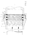
- this invention consists of a pipe coupling comprising a pair of threaded fittings, very easy to assemble, and which incorporates a trunco-conical washer (2) inside a bore opposite to the fitting (1) with a slot in the sense of the generatrices and where the pipe (3) passes through such washer contacting an inner cylindrical recess of the fitting opposed to the trunco-conical recess.
- This recess passes through another one outside it, with the same outer dimension as the larger base of the washer and which constitutes the fixing mean of two resilient sealing joints (4) inserted between two asymmetrical trapezoidal metallic washers (5) with straight outer sides and a third central washer with an isosceles trapezoid configuration (5'). All these joints have a cylindrical shape and a rectangular section with an inner sawtooth-shaped profile. The leaktightness is completed by means of a toric joint (6) inserted in the front face of one or both quick coupling fittings (1) and (1').
Landscapes
- Engineering & Computer Science (AREA)
- General Engineering & Computer Science (AREA)
- Mechanical Engineering (AREA)
- Quick-Acting Or Multi-Walled Pipe Joints (AREA)
Claims (2)
- Accouplement de tuyauterie comprenant une paire de raccords filetés (1, 1') et une rondelle tronconique (2) possédant une f-ente dans le sens de ses génératrices et disposée à l'intérieur d'une cavité tronconique dans l'un des raccords (1) et une tuyauterie (3) qui passe par ladite rondelle (2) et en contact avec une cavité cylindrique intérieure du raccord (1') opposé au raccord (1) dont la cavité est tronconique, caractérisé en ce qu'il comprend un joint d'étanchéité résilient simple (4) ayant une forme cylindrique et une section rectangulaire avec un trou intérieur en dent de scie qui est inséré entre deux rondelles métalliques asymétriques trapézoïdales (5) ayant des surfaces latérales droites axialement extérieures, l'une de ces rondelles métalliques (5) se trouvant en about contre un échelon formé entre ladite cavité tronconique et une cavité cylindrique externe adjacente qui est de la même dimension extérieure que la base radialement extérieure de cette rondelle (5), et un joint torique (6) inséré en face d'un de ces raccords.
- Accouplement de tuyauterie comprenant une paire de raccords filetés (1, 1') et une rondelle tronconique (2) possédant une fente dans le sens de ses génératrices et disposée à l'intérieur d'une cavité tronconique dans l'un des raccords (1) et une tuyauterie (3) qui passe par ladite rondelle (2) et en contact avec une cavité cylindrique intérieure du raccord (1') opposé au raccord (1) dont la cavité est tronconique, comprenant de plus deux joints résilients (4), chacun ayant une forme cylindrique et une section rectangulaire avec un trou intérieur en dent de scie lesquels sont insérés entre deux rondelles métalliques asymétriques trapézoïdales (5) ayant des surfaces latérales droites axialement extérieures, l'une de ces rondelles métalliques (5) se trouvant en about contre un échelon formé entre ladite cavité tronconique et une cavité cylindrique externe adjacente qui est de la même dimension extérieure que la base radialement extérieure de cette rondelle (5), une troisième rondelle centrale (5') ayant une configuration trapézoïdale isocèle entre les deux joints, et un joint torique (6) inséré en face d'un de ces raccords
Priority Applications (3)
| Application Number | Priority Date | Filing Date | Title |
|---|---|---|---|
| EP94500085A EP0682202B1 (fr) | 1994-05-12 | 1994-05-12 | Accessoires de raccordement pour accoupler des tuyaux |
| DE69415504T DE69415504T2 (de) | 1994-05-12 | 1994-05-12 | Fittings für Rohrkupplungen |
| AT94500085T ATE175013T1 (de) | 1994-05-12 | 1994-05-12 | Fittings für rohrkupplungen |
Applications Claiming Priority (1)
| Application Number | Priority Date | Filing Date | Title |
|---|---|---|---|
| EP94500085A EP0682202B1 (fr) | 1994-05-12 | 1994-05-12 | Accessoires de raccordement pour accoupler des tuyaux |
Publications (2)
| Publication Number | Publication Date |
|---|---|
| EP0682202A1 EP0682202A1 (fr) | 1995-11-15 |
| EP0682202B1 true EP0682202B1 (fr) | 1998-12-23 |
Family
ID=8218163
Family Applications (1)
| Application Number | Title | Priority Date | Filing Date |
|---|---|---|---|
| EP94500085A Expired - Lifetime EP0682202B1 (fr) | 1994-05-12 | 1994-05-12 | Accessoires de raccordement pour accoupler des tuyaux |
Country Status (3)
| Country | Link |
|---|---|
| EP (1) | EP0682202B1 (fr) |
| AT (1) | ATE175013T1 (fr) |
| DE (1) | DE69415504T2 (fr) |
Families Citing this family (14)
| Publication number | Priority date | Publication date | Assignee | Title |
|---|---|---|---|---|
| DE29921179U1 (de) * | 1999-12-03 | 2000-05-18 | Geiger, Hans-Peter, 73105 Dürnau | Universal-Verbindung |
| KR100820939B1 (ko) | 2006-09-29 | 2008-04-11 | 김용진 | 기밀용 패킹수단과 이를 구비한 관로 연결장치 |
| KR100864058B1 (ko) | 2007-01-11 | 2008-10-16 | 김용진 | 기밀용 패킹수단을 구비하는 뉴틸리티식 복층관용 관로 연결장치 |
| KR100864057B1 (ko) | 2007-01-11 | 2008-10-16 | 김용진 | 기밀용 패킹수단을 구비하는 뉴틸리티식 복합관용 관로 연결장치 |
| KR100864053B1 (ko) | 2007-01-11 | 2008-10-16 | 김용진 | 기밀용 패킹수단을 구비하는 뉴틸리티식 이중벽관용 관로 연결장치 |
| KR100864056B1 (ko) | 2007-01-11 | 2008-10-16 | 김용진 | 기밀용 패킹수단을 구비하는 뉴틸리티식 충진벽관용 관로 연결장치 |
| KR100864060B1 (ko) | 2007-01-11 | 2008-10-16 | 김용진 | 기밀용 패킹수단을 구비하는 뉴틸리티식 솔리드관용 관로 연결장치 |
| KR100864059B1 (ko) | 2007-01-11 | 2008-10-16 | 김용진 | 기밀용 패킹수단을 구비하는 뉴틸리티식 삼중 복층관용 관로 연결장치 |
| KR100864055B1 (ko) | 2007-01-11 | 2008-10-16 | 김용진 | 기밀용 패킹수단을 구비하는 뉴틸리티식 복합 복층관용 관로 연결장치 |
| CN102207232B (zh) * | 2011-03-02 | 2012-12-05 | 中煤张家口煤矿机械有限责任公司 | 万向连通器 |
| US9581245B2 (en) * | 2012-04-02 | 2017-02-28 | Hermes Microvision, Inc. | Metal seal for ultra high vacuum system |
| KR101295175B1 (ko) | 2013-05-20 | 2013-08-09 | (자)한진개발공사 | 상수관의 연결 구조 |
| US20170130877A1 (en) * | 2014-09-02 | 2017-05-11 | Actuant Corporation | Pipe connector |
| CN107575331B (zh) * | 2017-10-31 | 2025-01-21 | 李仁波 | 水力发电机 |
Family Cites Families (6)
| Publication number | Priority date | Publication date | Assignee | Title |
|---|---|---|---|---|
| DE716893C (de) * | 1939-01-10 | 1943-08-11 | Konrad Mielke | Rohrklemmverbindung mit durch Axialschub auf das Rohr gepresstem Spreizring |
| GB1267007A (fr) * | 1970-07-10 | 1972-03-15 | ||
| FR2316524A1 (fr) * | 1975-07-04 | 1977-01-28 | Plasson Maagan Michael Ind Ltd | Anneau fendu pour raccords de tuyaux |
| DE2910688A1 (de) * | 1979-03-19 | 1980-09-25 | Valvosanitaria Dei Fratelli Bu | Rohrkupplung |
| DE3521178A1 (de) * | 1985-06-13 | 1986-12-18 | Hewlett-Packard GmbH, 7030 Böblingen | Druckdichtes kupplungsstueck fuer ein rohr |
| DE4227080A1 (de) * | 1992-08-17 | 1994-02-24 | Hummel Anton Verwaltung | Klemmverschraubung für längliche Körper, insbesondere für Rohre, Kabel, Schläuche oder dergleichen |
-
1994
- 1994-05-12 EP EP94500085A patent/EP0682202B1/fr not_active Expired - Lifetime
- 1994-05-12 AT AT94500085T patent/ATE175013T1/de not_active IP Right Cessation
- 1994-05-12 DE DE69415504T patent/DE69415504T2/de not_active Expired - Fee Related
Also Published As
| Publication number | Publication date |
|---|---|
| EP0682202A1 (fr) | 1995-11-15 |
| DE69415504T2 (de) | 1999-07-29 |
| DE69415504D1 (de) | 1999-02-04 |
| ATE175013T1 (de) | 1999-01-15 |
Similar Documents
| Publication | Publication Date | Title |
|---|---|---|
| US6131957A (en) | Fixing construction for pipe joint | |
| US5437482A (en) | Pipe adapter flange | |
| US3680894A (en) | Joints between pipes of different diameters and couplings and gaskets for the same | |
| US3315970A (en) | Flexible gasket for high and low pressure pipe joints | |
| US3781041A (en) | Pipe and tube coupling | |
| EP0682202A1 (fr) | Accessoires de raccordement pour accoupler des tuyaux | |
| US3851901A (en) | Mechanical pipe couplings | |
| US7770941B2 (en) | Apparatus and method for supporting a pipe coupling | |
| US7793989B2 (en) | Locking connector with depressions | |
| KR101973850B1 (ko) | 관 연결용 조인트 | |
| US3482859A (en) | Pipe joint | |
| US20170074438A1 (en) | Pipe Coupling Apparatus | |
| US20060033333A1 (en) | Self locking threaded connector | |
| US2653040A (en) | Pipe coupling | |
| US3301576A (en) | Flanged joint | |
| JPH02107891A (ja) | ホース用ワンタッチジョイント | |
| US5180195A (en) | Joint locking system for pipe | |
| US1186621A (en) | Pipe-coupling. | |
| US3762684A (en) | Rotatable pipe coupling | |
| JP4939826B2 (ja) | 管継手の組立て方法 | |
| JPH07253187A (ja) | 管継手 | |
| US6692042B2 (en) | Profiled clamp and sleeve joint comprising such a profiled clamp | |
| JPH07280148A (ja) | 管のフランジ継手部構造 | |
| JP3436864B2 (ja) | 離脱防止形管継手 | |
| GB2047832A (en) | An improvement in compression joints |
Legal Events
| Date | Code | Title | Description |
|---|---|---|---|
| PUAI | Public reference made under article 153(3) epc to a published international application that has entered the european phase |
Free format text: ORIGINAL CODE: 0009012 |
|
| AK | Designated contracting states |
Kind code of ref document: A1 Designated state(s): AT BE CH DE DK ES FR GB GR IE IT LI LU MC NL PT SE |
|
| 17P | Request for examination filed |
Effective date: 19960515 |
|
| 17Q | First examination report despatched |
Effective date: 19970530 |
|
| GRAG | Despatch of communication of intention to grant |
Free format text: ORIGINAL CODE: EPIDOS AGRA |
|
| GRAG | Despatch of communication of intention to grant |
Free format text: ORIGINAL CODE: EPIDOS AGRA |
|
| GRAH | Despatch of communication of intention to grant a patent |
Free format text: ORIGINAL CODE: EPIDOS IGRA |
|
| GRAH | Despatch of communication of intention to grant a patent |
Free format text: ORIGINAL CODE: EPIDOS IGRA |
|
| GRAA | (expected) grant |
Free format text: ORIGINAL CODE: 0009210 |
|
| AK | Designated contracting states |
Kind code of ref document: B1 Designated state(s): AT BE CH DE DK ES FR GB GR IE IT LI LU MC NL PT SE |
|
| PG25 | Lapsed in a contracting state [announced via postgrant information from national office to epo] |
Ref country code: NL Free format text: LAPSE BECAUSE OF FAILURE TO SUBMIT A TRANSLATION OF THE DESCRIPTION OR TO PAY THE FEE WITHIN THE PRESCRIBED TIME-LIMIT Effective date: 19981223 Ref country code: LI Free format text: LAPSE BECAUSE OF FAILURE TO SUBMIT A TRANSLATION OF THE DESCRIPTION OR TO PAY THE FEE WITHIN THE PRESCRIBED TIME-LIMIT Effective date: 19981223 Ref country code: IT Free format text: LAPSE BECAUSE OF FAILURE TO SUBMIT A TRANSLATION OF THE DESCRIPTION OR TO PAY THE FEE WITHIN THE PRESCRIBED TIME-LIMIT;WARNING: LAPSES OF ITALIAN PATENTS WITH EFFECTIVE DATE BEFORE 2007 MAY HAVE OCCURRED AT ANY TIME BEFORE 2007. THE CORRECT EFFECTIVE DATE MAY BE DIFFERENT FROM THE ONE RECORDED. Effective date: 19981223 Ref country code: GR Free format text: LAPSE BECAUSE OF NON-PAYMENT OF DUE FEES Effective date: 19981223 Ref country code: ES Free format text: THE PATENT HAS BEEN ANNULLED BY A DECISION OF A NATIONAL AUTHORITY Effective date: 19981223 Ref country code: CH Free format text: LAPSE BECAUSE OF FAILURE TO SUBMIT A TRANSLATION OF THE DESCRIPTION OR TO PAY THE FEE WITHIN THE PRESCRIBED TIME-LIMIT Effective date: 19981223 Ref country code: BE Free format text: LAPSE BECAUSE OF FAILURE TO SUBMIT A TRANSLATION OF THE DESCRIPTION OR TO PAY THE FEE WITHIN THE PRESCRIBED TIME-LIMIT Effective date: 19981223 Ref country code: AT Free format text: LAPSE BECAUSE OF FAILURE TO SUBMIT A TRANSLATION OF THE DESCRIPTION OR TO PAY THE FEE WITHIN THE PRESCRIBED TIME-LIMIT Effective date: 19981223 |
|
| REF | Corresponds to: |
Ref document number: 175013 Country of ref document: AT Date of ref document: 19990115 Kind code of ref document: T |
|
| REG | Reference to a national code |
Ref country code: CH Ref legal event code: EP |
|
| REF | Corresponds to: |
Ref document number: 69415504 Country of ref document: DE Date of ref document: 19990204 |
|
| REG | Reference to a national code |
Ref country code: IE Ref legal event code: FG4D |
|
| PG25 | Lapsed in a contracting state [announced via postgrant information from national office to epo] |
Ref country code: SE Free format text: LAPSE BECAUSE OF FAILURE TO SUBMIT A TRANSLATION OF THE DESCRIPTION OR TO PAY THE FEE WITHIN THE PRESCRIBED TIME-LIMIT Effective date: 19990323 Ref country code: PT Free format text: LAPSE BECAUSE OF FAILURE TO SUBMIT A TRANSLATION OF THE DESCRIPTION OR TO PAY THE FEE WITHIN THE PRESCRIBED TIME-LIMIT Effective date: 19990323 Ref country code: DK Free format text: LAPSE BECAUSE OF FAILURE TO SUBMIT A TRANSLATION OF THE DESCRIPTION OR TO PAY THE FEE WITHIN THE PRESCRIBED TIME-LIMIT Effective date: 19990323 |
|
| ET | Fr: translation filed | ||
| PG25 | Lapsed in a contracting state [announced via postgrant information from national office to epo] |
Ref country code: LU Free format text: LAPSE BECAUSE OF NON-PAYMENT OF DUE FEES Effective date: 19990512 Ref country code: IE Free format text: LAPSE BECAUSE OF NON-PAYMENT OF DUE FEES Effective date: 19990512 Ref country code: GB Free format text: LAPSE BECAUSE OF NON-PAYMENT OF DUE FEES Effective date: 19990512 |
|
| NLV1 | Nl: lapsed or annulled due to failure to fulfill the requirements of art. 29p and 29m of the patents act | ||
| REG | Reference to a national code |
Ref country code: CH Ref legal event code: PL |
|
| PLBE | No opposition filed within time limit |
Free format text: ORIGINAL CODE: 0009261 |
|
| STAA | Information on the status of an ep patent application or granted ep patent |
Free format text: STATUS: NO OPPOSITION FILED WITHIN TIME LIMIT |
|
| PG25 | Lapsed in a contracting state [announced via postgrant information from national office to epo] |
Ref country code: MC Free format text: LAPSE BECAUSE OF NON-PAYMENT OF DUE FEES Effective date: 19991130 |
|
| 26N | No opposition filed | ||
| GBPC | Gb: european patent ceased through non-payment of renewal fee |
Effective date: 19990512 |
|
| PG25 | Lapsed in a contracting state [announced via postgrant information from national office to epo] |
Ref country code: FR Free format text: LAPSE BECAUSE OF NON-PAYMENT OF DUE FEES Effective date: 20000131 |
|
| PG25 | Lapsed in a contracting state [announced via postgrant information from national office to epo] |
Ref country code: DE Free format text: LAPSE BECAUSE OF NON-PAYMENT OF DUE FEES Effective date: 20000301 |
|
| REG | Reference to a national code |
Ref country code: FR Ref legal event code: ST |
|
| REG | Reference to a national code |
Ref country code: IE Ref legal event code: MM4A |