EP0682269A2 - Détermination de la position au moyen de mesures vectorielles - Google Patents
Détermination de la position au moyen de mesures vectorielles Download PDFInfo
- Publication number
- EP0682269A2 EP0682269A2 EP95303206A EP95303206A EP0682269A2 EP 0682269 A2 EP0682269 A2 EP 0682269A2 EP 95303206 A EP95303206 A EP 95303206A EP 95303206 A EP95303206 A EP 95303206A EP 0682269 A2 EP0682269 A2 EP 0682269A2
- Authority
- EP
- European Patent Office
- Prior art keywords
- line
- magnetic field
- vectors
- interference
- lines
- Prior art date
- Legal status (The legal status is an assumption and is not a legal conclusion. Google has not performed a legal analysis and makes no representation as to the accuracy of the status listed.)
- Granted
Links
- 239000013598 vector Substances 0.000 title claims abstract description 76
- 238000005259 measurement Methods 0.000 title claims abstract description 49
- 238000000034 method Methods 0.000 claims abstract description 33
- 238000004364 calculation method Methods 0.000 claims description 8
- 239000000696 magnetic material Substances 0.000 abstract description 2
- 239000002184 metal Substances 0.000 description 10
- 229910052751 metal Inorganic materials 0.000 description 10
- 230000009466 transformation Effects 0.000 description 10
- 238000005553 drilling Methods 0.000 description 6
- 238000006073 displacement reaction Methods 0.000 description 5
- 238000004458 analytical method Methods 0.000 description 3
- 230000005389 magnetism Effects 0.000 description 3
- 238000010845 search algorithm Methods 0.000 description 3
- 238000000844 transformation Methods 0.000 description 3
- 238000013459 approach Methods 0.000 description 2
- 230000004888 barrier function Effects 0.000 description 2
- 238000004422 calculation algorithm Methods 0.000 description 2
- 230000008859 change Effects 0.000 description 2
- 238000010586 diagram Methods 0.000 description 2
- 230000000694 effects Effects 0.000 description 2
- 230000005684 electric field Effects 0.000 description 2
- 230000004907 flux Effects 0.000 description 2
- 230000002452 interceptive effect Effects 0.000 description 2
- 239000011159 matrix material Substances 0.000 description 2
- 239000011435 rock Substances 0.000 description 2
- 229910000831 Steel Inorganic materials 0.000 description 1
- 230000009471 action Effects 0.000 description 1
- 230000003466 anti-cipated effect Effects 0.000 description 1
- 238000005422 blasting Methods 0.000 description 1
- 238000004590 computer program Methods 0.000 description 1
- 230000007423 decrease Effects 0.000 description 1
- 230000003247 decreasing effect Effects 0.000 description 1
- 230000001419 dependent effect Effects 0.000 description 1
- 230000005672 electromagnetic field Effects 0.000 description 1
- 239000002360 explosive Substances 0.000 description 1
- 238000000605 extraction Methods 0.000 description 1
- 230000005484 gravity Effects 0.000 description 1
- 238000012804 iterative process Methods 0.000 description 1
- 238000013507 mapping Methods 0.000 description 1
- 239000000463 material Substances 0.000 description 1
- 230000035939 shock Effects 0.000 description 1
- 239000010959 steel Substances 0.000 description 1
- 230000009897 systematic effect Effects 0.000 description 1
- 238000009966 trimming Methods 0.000 description 1
- 230000000007 visual effect Effects 0.000 description 1
Images


Classifications
-
- G—PHYSICS
- G01—MEASURING; TESTING
- G01V—GEOPHYSICS; GRAVITATIONAL MEASUREMENTS; DETECTING MASSES OR OBJECTS; TAGS
- G01V3/00—Electric or magnetic prospecting or detecting; Measuring magnetic field characteristics of the earth, e.g. declination, deviation
- G01V3/08—Electric or magnetic prospecting or detecting; Measuring magnetic field characteristics of the earth, e.g. declination, deviation operating with magnetic or electric fields produced or modified by objects or geological structures or by detecting devices
Definitions
- the present invention relates to a method of determining from a measurement region, the location of a source of a physical phenomenon.
- the invention is particularly suitable for applications where the source is "invisible" from the measurement location such as subterranean ranging.
- the measurement region could be a well borehole being drilled and the source could be an adjacent well borehole.
- the present invention provides a method of determining from a measurement region the location of a source of a physical phenomenon comprising detecting the direction of the phenomenon as a vector at at least two spatially separated points in the measurement region and finding a line which is intersected by the lines including said vectors.
- the physical phenomenon is a magnetic field.
- a drilled well usually contains some magnetically permeable material such as a metal liner extending along the borehole or possibly a drillstring itself.
- the metal influences the magnetic field which would normally act on an adjacent well (ie: the earth's magnetic field). This influence is generally referred to as "magnetic interference".
- the metal in the borehole typically behaves as a cylindrical bar magnet having the typical magnetic field pattern extending around it. The field strength decreases with distance from the borehole.
- the magnetic interference due to the metal in the borehole can be measured as a vector whose orientation depends on the location of the measurement point within the magnetic field.
- the present invention is based on the realisation that if a cylindrical bar magnet, or in this case the borehole, is viewed "end on", ie: looking down the borehole, the magnetic field vectors appear to intersect at a particular point. In other words, the magnetic field lines all intersect the longitudinal axis of the borehole.
- a line intersected by all detected magnetic field vectors represents the longitudinal axis of the source of magnetic interference. Knowing the location of the longitudinal axis, the minimum distance between a well being drilled and an adjacent borehole can be determined.
- knowing the location of the longitudinal axis of a source of a phenomenon enables an approximate determination of the distance of the source from the region where the measurements are being taken.
- the azimuth and inclination of the source is already known, its position can be determined from only two measured vectors. If only one of azimuth and inclination is known, three vectors will normally be sufficient to determine the position of the axis of the source with reasonable certainty. If the azimuth and inclination are not known, at least four vectors will be needed to determine the position of the axis of the source with any certainty. (There are an infinite number of straight lines which will join three spatially separated straight lines but it is unlikely that more than two straight lines will join four spatially separated straight lines, one being the measurement line, the second being the target line.) For greater accuracy it will be preferable to take more than only three or four vector measurements even with prior knowledge of one or more the borehole parameters. Then, allowing for errors, the longitudinal axis of the source will be the line which is most nearly intersected by all of the measured vectors.
- a typical downhole survey tool is typically provided with three mutually perpendicular fluxgate magnetometers for measuring flux components to generate a flux vector, and three accelerometers for taking measurements of the gravitational field at different locations down the borehole. These are usually provided in a single sensor package and sensor information is stored to memory or transmitted to the surface using MWD (measurement while drilling) techniques, or via a wire link.
- MWD measurement while drilling
- the interference from the metal in an adjacent well is normally from the tubular elements within it, eg: casing, drill pipe, collars etc. The interference surrounding them is determined by the magnetism (induced and permanent) within the metal. The shape of the interference pattern is determined by the homogeneity of the magnetism and the shape of the metal.
- the magnetism is homogeneous within a joint of a casing, drill pipe or collars and their shape is normally rotationally symmetrical and tubular.
- the effect of this on the interference pattern is that it has a sense of symmetry looking down the longitudinal axis of the cylinders.
- the technique of the present invention makes use of this symmetry.
- Objects in a well such as pipe sections etc. are often screwed together to form a long continuous cylinder.
- the longitudinal axis of these items lies along the wellbore path.
- the magnetic field emanates from the cylinders as if they were cylindrical magnets.
- the magnetometers of a downhole tool will detect the earth's magnetic field. In the vicinity of another well they will also detect the interference field. In order to determine the interference vector at any point downhole, first the normally present earth's magnetic field must be subtracted as will be explained in more detail below.
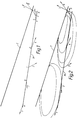
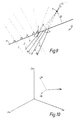
- FIGURE 1 shows the relationship between the path M of the borehole being drilled (measurement line), the line of the adjacent borehole T (target line) and the calculated interference vectors 1-7 measured at various points a-g along path M.
- the illustrated interference vectors are due solely to interference from adjacent borehole T. In other words the earth's field and other interference to be described below has been subtracted from the measured values.
- Figure 2 additionally illustrates the magnetic field lines, due to "cylindrical magnets" in the target well, which cause the interference.
- the measured vectors are tangential to the field lines.
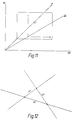
- Figure 3 shows the interference vectors extended (shown as dotted lines). As noted above, the magnitude of the vectors does not need to be known. Thus, in this technique, each vector is extended to an infinite line in space.
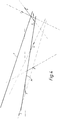
- the lines including the vectors 1-7 appear to intersect at random points in space. If the view point is changed and the lines are reviewed looking down the target line T, the vectors appear to intersect at a common point.
- the plane of Figure 5 is perpendicular to the target line and the lines including the vectors all cross the target line T.
- the lines including the vectors also cross the measurement line M, as shown in Figure 6 in which the measurement line M is parallel to the plane of the paper.
- the lines including the vectors are a special set which all cross two lines, T and M.
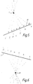
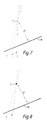
- the position of M is known and therefore the position of T can be found using techniques to be described below. If no information is available on the spatial location of T, at least four vectors will generally be needed to determine the azimuth, inclination and displacement D of T from M, as shown, for example, in Figure 9. If a parameter of the target line is already known, such as azimuth, inclination or direction, generally only three vectors will be required as shown in Figure 7, although in special cases (e.g. parallel vectors) will not give the required information. Approximation techniques would be used, as explained later on. If the azimuth and inclination are already known, a solution for T can be found with only two vectors, as indicated in Figure 8.
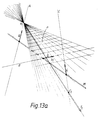
- Figure 9 shows a practical example of a drilling operation with the interference vectors typically measured at various points a-j along the measurement line.
- Lines 1-10 are the extended lines which include the linear interference vectors.
- Lines 1-5 are extended from interference vectors measured at points a,b,c,d,e along the measurement line M. At these points there is no appreciable influence from the target well T.
- the interference vectors at points a,b,c,d,e have been corrected for the effects of the earth's magnetic field and are simply due to interference from the drilling drillstring itself and inherent errors. For example, it is assumed that the measurement line follows a straight azimuth but there may in fact be slight deviations which will cause errors.
- the magnetic interference can come from anywhere on the target well, it can leave the target well at any angle, and can be of any strength. It is the particular shape of the field which enables the source to be identified using the method of this invention.
- the drilling tool has three mutually perpendicular fluxgate magnetometers which produce measured values H x , H y , H z , (x,y,z being the axes of the tool coordinate system) and three mutually perpendicular accelerometers which give gravitational measurements G x , G y , G z .
- the 'er' and 'd' components need to be separated to give the 'i' (outside interference) components.
- the 'er' and 'd' components are constant or consistent and only the 'i' vector changes and therefore calculation of the 'i' vector is a simple matter of subtraction.
- the initial vectors will consist only of 'er' and 'd' and can simply be subtracted once the 'i' factor comes into play.
- the measurement line may be parallel to the target line or tangential to one of the magnetic field lines, in which case the interference vector may not change at different locations along the measurement line, and no realistic determination of the position of the target line can be made. In such unusual cases the problem can be overcome by changing the measurement line direction slightly.
- drillstring interference “d” could be eliminated or reduced to an insignificant level by isolating the survey instrument, eg: distancing the survey package from steel within the measurement well or simply using a non-magnetic material in the measurement well. Inherent errors "er” can be removed by using a survey device to measure the azimuth which is not reliant on the magnetic field, such as a gyro.
- the next step is to find the viewing plane at which the lines including the vectors appear to cross, as shown in Figure 5.
- this has been done very simply using a 3-D CAD system and changing the viewing angle or viewing plane to find the plane in which the vectors appear to cross.
- a computer program could be produced to do the finding automatically, possibly by an iterative process.
- the best fit might be the line which all vectors approach most closely, which can be calculated by the program.
- This line therefore passes through A, B and C and therefore satisfies the requirement for T.
- this line T is not unique as the point a1 was chosen; there are an infinite number of possible choices for point a1 (a2, a3.%) giving rise to an infinite number of possible lines T (T1, T2).
- T is not unique (see Figure 13b for an example of another line T2), and it is straightforward to show that there are always lines T a and T b which could be at an angle to one another of between 0 and 90 degrees.
- the basic problem is therefore the determination of the line of target from four given interference vectors emanating from the target line and measured from given measurement points on the measurement line.
- the target line has the property that, if we look along it, the interference vectors appear to be concurrent (i.e. pass through a common point). It is this property that will be utilised to determine the target line ( Figure 1).
- the search for the target line may be done computationally, with or without the aid of computer graphics. Using computer graphics does, however, provide us with an effective visual aid, and is particularly useful in establishing an initial search region, and in enabling us to decide whether the search is converging satisfactorily. We are thus faced with the problem of representing a three-dimensional object (the target vectors and measurement line) in two dimensions (the viewplane or plane of projection).
- the two-dimensional representation of three-dimensional objects requires the introduction of certain mathematical transformations.
- the target interference vectors are specified by their start and finish xyz coordinates in a certain three-dimensional coordinate system.
- This coordinate system is known as the world coordinate system. If we wish to project the three-dimensional object on to a two-dimensional viewing plane, other coordinate systems have to be introduced, namely the three-dimensional eye coordinate systems, and the two-dimensional screen coordinate system.
- a point on our three-dimensional object, specified by its world coordinates (X w , Y w , Z w ), has to be mapped to a corresponding point specified by its screen coordinates (X,Y).
- the mapping from world coordinates to screen coordinates is carried out in two stages. We first of all assume that our eye is in a certain position in three-dimensional space (the viewpoint). We then choose a coordinate system such that the origin is at the viewpoint, and the z-axis points to the origin of the world coordinate system ( Figure 10). This coordinate system is the eye coordinate system.
- a point with world coordinates (x w ,y w ,z w ) is transformed to a point with eye coordinates (x e ,y e ,z e ).
- This transformation is called the viewing transformation.
- V is the viewpoint transformation matrix given by where p, ⁇ , and ⁇ are the spherical coordinates of the viewpoint in world coordinate space.
- p, ⁇ , and ⁇ changes the viewpoint and hence the line of sight.
- a target interference vector is specified by two points, namely its initial and final points specified in world coordinates. For a given viewpoint, we can now calculate the corresponding two-dimensional screen coordinates of these points. These two points on the screen plane specify a unique straight line. Thus, when we transform the four target interference vectors, we obtain four straight lines in the screen plane.
- the next step in the determination of the line of target is to vary the viewpoint/origin vector until the six points of intersection coincide or are sufficiently close. Once the convergence criterion has been met the values of ⁇ , the inclination, and ⁇ , the asimuth provide the direction of the line of sight. We can now therefore project the projected point corresponding to target line back into world coordinates to establish the target line.4.
- intersection points could be weighted according to the angles between the intersecting lines (projected or in real space); lines that are almost parallel will have a highly variable point of intersection depending on the accuracy to which they are known, and should have a low weighting. Conversely, intersection points of lines which are close to perpendicular should be given a high weighting.
- the search can be made finer by decreasing the viewing distance.
- search procedure could also be implemented using interactive computer graphics.
- the calculations to be carried out are not complex, and the speed of present computers allied to high resolution graphics could lead to an effective means of solution using a combination of user-driven and algorithm-driven search techniques.
- the direction ratios of the common perpendicular are (m2n2 - m2n1):(n1l2 - n2l1):(l1m2 - l2m1) and using simple analytic geometry, it is straightforward to calculate the length of this common perpendicular (i.e. the shortest distance between the two lines).
- the technique of the present invention could be used to locate targets emitting other fields.
- Other examples include seismic fields, alternating electromagnetic fields and possibly even gravitational fields.
- Parallel wells are used in the explosives industry for trimming of rock faces and bulk blasting to pre-fractured boundaries. It is normally important for the relative displacement and the position of these wells to be known to create effective trims and contain a bulk blast to prevent it from fracturing adjacent rock.
- Wells or boreholes are also used in the creation of tunnels, such as underneath rivers.
- a "target” could be placed on a river bed to ensure that a borehole was always a predetermined distance beneath the earth's surface.
Landscapes
- Life Sciences & Earth Sciences (AREA)
- Engineering & Computer Science (AREA)
- Physics & Mathematics (AREA)
- Remote Sensing (AREA)
- Geology (AREA)
- Environmental & Geological Engineering (AREA)
- Electromagnetism (AREA)
- General Life Sciences & Earth Sciences (AREA)
- General Physics & Mathematics (AREA)
- Geophysics (AREA)
- Geophysics And Detection Of Objects (AREA)
- Measuring Pulse, Heart Rate, Blood Pressure Or Blood Flow (AREA)
- Vehicle Body Suspensions (AREA)
- Transmission And Conversion Of Sensor Element Output (AREA)
Applications Claiming Priority (2)
| Application Number | Priority Date | Filing Date | Title |
|---|---|---|---|
| GB9409550A GB9409550D0 (en) | 1994-05-12 | 1994-05-12 | Location determination using vector measurements |
| GB9409550 | 1994-05-12 |
Publications (3)
| Publication Number | Publication Date |
|---|---|
| EP0682269A2 true EP0682269A2 (fr) | 1995-11-15 |
| EP0682269A3 EP0682269A3 (fr) | 1998-01-28 |
| EP0682269B1 EP0682269B1 (fr) | 2001-08-08 |
Family
ID=10755039
Family Applications (1)
| Application Number | Title | Priority Date | Filing Date |
|---|---|---|---|
| EP95303206A Expired - Lifetime EP0682269B1 (fr) | 1994-05-12 | 1995-05-12 | Détermination de la position au moyen de mesures vectorielles |
Country Status (6)
| Country | Link |
|---|---|
| US (1) | US5675488A (fr) |
| EP (1) | EP0682269B1 (fr) |
| CA (1) | CA2149196C (fr) |
| DE (1) | DE69522040T2 (fr) |
| GB (1) | GB9409550D0 (fr) |
| NO (1) | NO313774B1 (fr) |
Cited By (10)
| Publication number | Priority date | Publication date | Assignee | Title |
|---|---|---|---|---|
| US5960370A (en) * | 1996-08-14 | 1999-09-28 | Scientific Drilling International | Method to determine local variations of the earth's magnetic field and location of the source thereof |
| GB2398638A (en) * | 2003-02-18 | 2004-08-25 | Pathfinder Energy Services Inc | Passive ranging determining the position of a subterranean magnetic structure from within a nearby borehole |
| GB2402746A (en) * | 2003-06-09 | 2004-12-15 | Pathfinder Energy Services Inc | Well twinning techniques in borehole surveying |
| US6882937B2 (en) | 2003-02-18 | 2005-04-19 | Pathfinder Energy Services, Inc. | Downhole referencing techniques in borehole surveying |
| US7002484B2 (en) | 2002-10-09 | 2006-02-21 | Pathfinder Energy Services, Inc. | Supplemental referencing techniques in borehole surveying |
| US8828225B2 (en) | 2004-08-06 | 2014-09-09 | Asahi Kasei Medical Co., Ltd. | Polysulfone hemodialyzer |
| EP2818632A2 (fr) | 2013-06-25 | 2014-12-31 | Gyrodata, Incorporated | Techniques de positionnement dans des environnements à puits multiples |
| US8947094B2 (en) | 2011-07-18 | 2015-02-03 | Schlumber Technology Corporation | At-bit magnetic ranging and surveying |
| US11175431B2 (en) | 2017-06-14 | 2021-11-16 | Gyrodata, Incorporated | Gyro-magnetic wellbore surveying |
| US11193363B2 (en) | 2017-12-04 | 2021-12-07 | Gyrodata, Incorporated | Steering control of a drilling tool |
Families Citing this family (40)
| Publication number | Priority date | Publication date | Assignee | Title |
|---|---|---|---|---|
| US7027926B2 (en) * | 2004-04-19 | 2006-04-11 | Pathfinder Energy Services, Inc. | Enhanced measurement of azimuthal dependence of subterranean parameters |
| US7080460B2 (en) * | 2004-06-07 | 2006-07-25 | Pathfinder Energy Sevices, Inc. | Determining a borehole azimuth from tool face measurements |
| US7219749B2 (en) * | 2004-09-28 | 2007-05-22 | Vector Magnetics Llc | Single solenoid guide system |
| US7103982B2 (en) * | 2004-11-09 | 2006-09-12 | Pathfinder Energy Services, Inc. | Determination of borehole azimuth and the azimuthal dependence of borehole parameters |
| US8026722B2 (en) * | 2004-12-20 | 2011-09-27 | Smith International, Inc. | Method of magnetizing casing string tubulars for enhanced passive ranging |
| CA2490953C (fr) * | 2004-12-20 | 2011-03-29 | Pathfinder Energy Services, Inc. | Magnetisation de tubage a mire de puits pour telemetrie passive amelioree |
| US8294468B2 (en) | 2005-01-18 | 2012-10-23 | Baker Hughes Incorporated | Method and apparatus for well-bore proximity measurement while drilling |
| US7436184B2 (en) * | 2005-03-15 | 2008-10-14 | Pathfinder Energy Services, Inc. | Well logging apparatus for obtaining azimuthally sensitive formation resistivity measurements |
| US7414405B2 (en) * | 2005-08-02 | 2008-08-19 | Pathfinder Energy Services, Inc. | Measurement tool for obtaining tool face on a rotating drill collar |
| US20070223822A1 (en) * | 2006-03-20 | 2007-09-27 | Pathfinder Energy Services, Inc. | Data compression method used in downhole applications |
| US7538650B2 (en) | 2006-07-17 | 2009-05-26 | Smith International, Inc. | Apparatus and method for magnetizing casing string tubulars |
| US7712519B2 (en) | 2006-08-25 | 2010-05-11 | Smith International, Inc. | Transverse magnetization of casing string tubulars |
| US7617049B2 (en) * | 2007-01-23 | 2009-11-10 | Smith International, Inc. | Distance determination from a magnetically patterned target well |
| WO2008137097A1 (fr) * | 2007-05-03 | 2008-11-13 | Smith International, Inc. | Procédé d'optimisation d'un trajet de puits au cours du forage |
| US7725263B2 (en) * | 2007-05-22 | 2010-05-25 | Smith International, Inc. | Gravity azimuth measurement at a non-rotating housing |
| US7558675B2 (en) * | 2007-07-25 | 2009-07-07 | Smith International, Inc. | Probablistic imaging with azimuthally sensitive MWD/LWD sensors |
| US9121967B2 (en) | 2007-08-31 | 2015-09-01 | Baker Hughes Incorporated | Method and apparatus for well-bore proximity measurement while drilling |
| CA2754152A1 (fr) * | 2009-03-17 | 2010-09-23 | Smith International, Inc. | Modeles d'erreurs relative et absolue pour des puits souterrains |
| US8195400B2 (en) * | 2009-05-08 | 2012-06-05 | Smith International, Inc. | Directional resistivity imaging using harmonic representations |
| US9010461B2 (en) | 2009-06-01 | 2015-04-21 | Halliburton Energy Services, Inc. | Guide wire for ranging and subsurface broadcast telemetry |
| US8912915B2 (en) | 2009-07-02 | 2014-12-16 | Halliburton Energy Services, Inc. | Borehole array for ranging and crosswell telemetry |
| US8271199B2 (en) * | 2009-12-31 | 2012-09-18 | Smith International, Inc. | Binning method for borehole imaging |
| US9581718B2 (en) | 2010-03-31 | 2017-02-28 | Halliburton Energy Services, Inc. | Systems and methods for ranging while drilling |
| US8600115B2 (en) | 2010-06-10 | 2013-12-03 | Schlumberger Technology Corporation | Borehole image reconstruction using inversion and tool spatial sensitivity functions |
| US9658360B2 (en) | 2010-12-03 | 2017-05-23 | Schlumberger Technology Corporation | High resolution LWD imaging |
| US9238959B2 (en) | 2010-12-07 | 2016-01-19 | Schlumberger Technology Corporation | Methods for improved active ranging and target well magnetization |
| US8856320B2 (en) | 2011-02-16 | 2014-10-07 | International Business Machines Corporation | Locating a target computer device in an array |
| CN102419457B (zh) * | 2011-07-29 | 2013-04-03 | 重庆大学 | 一种利用单个竖直钻孔的电视图像确定深部岩体结构面产状的方法 |
| AU2012379683B2 (en) | 2012-05-09 | 2016-02-25 | Halliburton Energy Services, Inc. | Enhanced geothermal systems and methods |
| US9151150B2 (en) | 2012-10-23 | 2015-10-06 | Baker Hughes Incorporated | Apparatus and methods for well-bore proximity measurement while drilling |
| US9422803B2 (en) | 2012-11-01 | 2016-08-23 | Baker Hughes Incorporated | Passive magnetic ranging for SAGD and relief wells via a linearized trailing window kalman filter |
| US8960280B2 (en) * | 2013-01-23 | 2015-02-24 | Microseismic, Inc. | Method for determining fracture plane orientation using passive seismic signals |
| US10094850B2 (en) | 2014-06-27 | 2018-10-09 | Schlumberger Technology Corporation | Magnetic ranging while rotating |
| US10031153B2 (en) | 2014-06-27 | 2018-07-24 | Schlumberger Technology Corporation | Magnetic ranging to an AC source while rotating |
| US11035672B2 (en) * | 2015-05-12 | 2021-06-15 | The Boeing Company | Sensing of a magnetic target |
| US11151762B2 (en) | 2015-11-03 | 2021-10-19 | Ubiterra Corporation | Systems and methods for shared visualization and display of drilling information |
| US20170122095A1 (en) * | 2015-11-03 | 2017-05-04 | Ubiterra Corporation | Automated geo-target and geo-hazard notifications for drilling systems |
| US11320560B2 (en) | 2017-06-08 | 2022-05-03 | Halliburton Energy Services, Inc. | Downhole ranging using spatially continuous constraints |
| CA3180585A1 (fr) | 2020-06-10 | 2021-12-16 | Yuliy Aleksandrovich DASHEVSKIY | Telemetrie magnetique active par injection de courant de tete de puits |
| WO2024221093A1 (fr) * | 2023-04-26 | 2024-10-31 | Phoenix Technology Services | Réseau de capteurs magnéto-résistifs et procédés d'utilisation associés |
Family Cites Families (8)
| Publication number | Priority date | Publication date | Assignee | Title |
|---|---|---|---|---|
| US3725777A (en) * | 1971-06-07 | 1973-04-03 | Shell Oil Co | Method for determining distance and direction to a cased borehole using measurements made in an adjacent borehole |
| US4072200A (en) * | 1976-05-12 | 1978-02-07 | Morris Fred J | Surveying of subterranean magnetic bodies from an adjacent off-vertical borehole |
| AT374595B (de) * | 1980-12-30 | 1984-05-10 | Norbert Dr Nessler | Ortungsverfahren |
| NO861800L (no) * | 1985-08-21 | 1987-02-23 | Nl Industries Inc | Ledende hylstre for magnetometre. |
| GB2241583A (en) * | 1990-03-03 | 1991-09-04 | Baroid Technology Inc | Determination of magnetic interference in a borehole |
| DE4101348C2 (de) * | 1991-01-18 | 1994-07-14 | Bergwerksverband Gmbh | Vorrichtung zur Bestimmung der Richtung einer Zielbohrstange gegenüber der magnetischen Nordrichtung |
| US5913820A (en) * | 1992-08-14 | 1999-06-22 | British Telecommunications Public Limited Company | Position location system |
| US5541517A (en) * | 1994-01-13 | 1996-07-30 | Shell Oil Company | Method for drilling a borehole from one cased borehole to another cased borehole |
-
1994
- 1994-05-12 GB GB9409550A patent/GB9409550D0/en active Pending
-
1995
- 1995-05-11 CA CA002149196A patent/CA2149196C/fr not_active Expired - Lifetime
- 1995-05-11 NO NO19951869A patent/NO313774B1/no not_active IP Right Cessation
- 1995-05-12 US US08/440,152 patent/US5675488A/en not_active Expired - Lifetime
- 1995-05-12 DE DE69522040T patent/DE69522040T2/de not_active Expired - Lifetime
- 1995-05-12 EP EP95303206A patent/EP0682269B1/fr not_active Expired - Lifetime
Non-Patent Citations (1)
| Title |
|---|
| None |
Cited By (15)
| Publication number | Priority date | Publication date | Assignee | Title |
|---|---|---|---|---|
| US5960370A (en) * | 1996-08-14 | 1999-09-28 | Scientific Drilling International | Method to determine local variations of the earth's magnetic field and location of the source thereof |
| US7002484B2 (en) | 2002-10-09 | 2006-02-21 | Pathfinder Energy Services, Inc. | Supplemental referencing techniques in borehole surveying |
| US6882937B2 (en) | 2003-02-18 | 2005-04-19 | Pathfinder Energy Services, Inc. | Downhole referencing techniques in borehole surveying |
| US6937023B2 (en) | 2003-02-18 | 2005-08-30 | Pathfinder Energy Services, Inc. | Passive ranging techniques in borehole surveying |
| GB2398638A (en) * | 2003-02-18 | 2004-08-25 | Pathfinder Energy Services Inc | Passive ranging determining the position of a subterranean magnetic structure from within a nearby borehole |
| GB2398638B (en) * | 2003-02-18 | 2006-08-02 | Pathfinder Energy Services Inc | Passive ranging techniques in borehole surveying |
| GB2402746A (en) * | 2003-06-09 | 2004-12-15 | Pathfinder Energy Services Inc | Well twinning techniques in borehole surveying |
| US6985814B2 (en) | 2003-06-09 | 2006-01-10 | Pathfinder Energy Services, Inc. | Well twinning techniques in borehole surveying |
| GB2402746B (en) * | 2003-06-09 | 2006-11-22 | Pathfinder Energy Services Inc | Well twinning techniques in borehole surveying |
| US8828225B2 (en) | 2004-08-06 | 2014-09-09 | Asahi Kasei Medical Co., Ltd. | Polysulfone hemodialyzer |
| US8947094B2 (en) | 2011-07-18 | 2015-02-03 | Schlumber Technology Corporation | At-bit magnetic ranging and surveying |
| GB2492666B (en) * | 2011-07-18 | 2015-03-18 | Schlumberger Holdings | At-bit magnetic ranging and surveying |
| EP2818632A2 (fr) | 2013-06-25 | 2014-12-31 | Gyrodata, Incorporated | Techniques de positionnement dans des environnements à puits multiples |
| US11175431B2 (en) | 2017-06-14 | 2021-11-16 | Gyrodata, Incorporated | Gyro-magnetic wellbore surveying |
| US11193363B2 (en) | 2017-12-04 | 2021-12-07 | Gyrodata, Incorporated | Steering control of a drilling tool |
Also Published As
| Publication number | Publication date |
|---|---|
| CA2149196A1 (fr) | 1995-11-13 |
| NO951869D0 (no) | 1995-05-11 |
| EP0682269B1 (fr) | 2001-08-08 |
| US5675488A (en) | 1997-10-07 |
| DE69522040T2 (de) | 2001-11-15 |
| NO313774B1 (no) | 2002-11-25 |
| DE69522040D1 (de) | 2001-09-13 |
| EP0682269A3 (fr) | 1998-01-28 |
| CA2149196C (fr) | 2005-11-01 |
| NO951869L (no) | 1995-11-13 |
| GB9409550D0 (en) | 1994-06-29 |
Similar Documents
| Publication | Publication Date | Title |
|---|---|---|
| EP0682269A2 (fr) | Détermination de la position au moyen de mesures vectorielles | |
| CA2187487C (fr) | Aimant tournant pour determiner la distance et la direction | |
| Feng et al. | Measuring fracture orientation at exposed rock faces by using a non-reflector total station | |
| US5512830A (en) | Measurement of vector components of static field perturbations for borehole location | |
| CA2458246C (fr) | Techniques de telemetrie passive en prospection par trou de forage | |
| EP0425569B1 (fr) | Systeme et procede de localisation d'une sonde de sous-sol | |
| US3725777A (en) | Method for determining distance and direction to a cased borehole using measurements made in an adjacent borehole | |
| US20020130663A1 (en) | Electromagnetic borehole surveying method | |
| GB2398879A (en) | Determination of rotational offset between two borehole gravity measurement devices | |
| CA2212925C (fr) | Methode pour determiner les variations locales du champ magnetique terrestre et l'emplacement des sources de perturbation | |
| US11299979B2 (en) | Magnetic distance and direction measurements from a first borehole to a second borehole | |
| GB2294344A (en) | Interpolating curves, e.g. relating to geological faults | |
| NO20190515A1 (en) | Improved structural modelling | |
| Feng | Novel methods for 3-D semi-automatic mapping of fracture geometry at exposed rock faces | |
| Campbell Jr | Stratigraphic applications of dipmeter data in Mid-Continent | |
| Butler et al. | Analytical modeling of magnetic and gravity signatures of unexploded ordnance | |
| Godio et al. | Integrated data processing for archeological magnetic surveys | |
| Ekseth et al. | High-Integrity Wellbore Surveying | |
| WO1996035859A1 (fr) | Procede de forage directionnel | |
| WO2016133517A1 (fr) | Procédé de réduction au minimum d'effets de trou de forage pour un outil d'induction multicomposante | |
| Collar et al. | Application of drillhole vector magnetic measurements to resolve the position of existing underground structures | |
| Truex | Directional survey problems, East Wilmington oil field, California | |
| GB2317454A (en) | Magnetic field measurement in a sub-surface wellpath | |
| Thomas et al. | Determination of a spatial fracture network | |
| Naville et al. | Orientation of 3 component rig-source VSPs |
Legal Events
| Date | Code | Title | Description |
|---|---|---|---|
| PUAI | Public reference made under article 153(3) epc to a published international application that has entered the european phase |
Free format text: ORIGINAL CODE: 0009012 |
|
| AK | Designated contracting states |
Kind code of ref document: A2 Designated state(s): DE FR GB |
|
| PUAL | Search report despatched |
Free format text: ORIGINAL CODE: 0009013 |
|
| AK | Designated contracting states |
Kind code of ref document: A3 Designated state(s): DE FR GB |
|
| 17P | Request for examination filed |
Effective date: 19980316 |
|
| 17Q | First examination report despatched |
Effective date: 19991125 |
|
| GRAG | Despatch of communication of intention to grant |
Free format text: ORIGINAL CODE: EPIDOS AGRA |
|
| GRAG | Despatch of communication of intention to grant |
Free format text: ORIGINAL CODE: EPIDOS AGRA |
|
| GRAH | Despatch of communication of intention to grant a patent |
Free format text: ORIGINAL CODE: EPIDOS IGRA |
|
| GRAH | Despatch of communication of intention to grant a patent |
Free format text: ORIGINAL CODE: EPIDOS IGRA |
|
| GRAA | (expected) grant |
Free format text: ORIGINAL CODE: 0009210 |
|
| AK | Designated contracting states |
Kind code of ref document: B1 Designated state(s): DE FR GB |
|
| REF | Corresponds to: |
Ref document number: 69522040 Country of ref document: DE Date of ref document: 20010913 |
|
| ET | Fr: translation filed | ||
| REG | Reference to a national code |
Ref country code: GB Ref legal event code: IF02 |
|
| PLBE | No opposition filed within time limit |
Free format text: ORIGINAL CODE: 0009261 |
|
| STAA | Information on the status of an ep patent application or granted ep patent |
Free format text: STATUS: NO OPPOSITION FILED WITHIN TIME LIMIT |
|
| 26N | No opposition filed | ||
| PGFP | Annual fee paid to national office [announced via postgrant information from national office to epo] |
Ref country code: FR Payment date: 20110511 Year of fee payment: 17 |
|
| REG | Reference to a national code |
Ref country code: FR Ref legal event code: ST Effective date: 20130131 |
|
| PG25 | Lapsed in a contracting state [announced via postgrant information from national office to epo] |
Ref country code: FR Free format text: LAPSE BECAUSE OF NON-PAYMENT OF DUE FEES Effective date: 20120531 |
|
| REG | Reference to a national code |
Ref country code: DE Ref legal event code: R082 Ref document number: 69522040 Country of ref document: DE Representative=s name: WEISSE, RENATE, DIPL.-PHYS. DR.-ING., DE |
|
| PGFP | Annual fee paid to national office [announced via postgrant information from national office to epo] |
Ref country code: GB Payment date: 20140425 Year of fee payment: 20 |
|
| PGFP | Annual fee paid to national office [announced via postgrant information from national office to epo] |
Ref country code: DE Payment date: 20140602 Year of fee payment: 20 |
|
| REG | Reference to a national code |
Ref country code: DE Ref legal event code: R071 Ref document number: 69522040 Country of ref document: DE |
|
| REG | Reference to a national code |
Ref country code: DE Ref legal event code: R071 Ref document number: 69522040 Country of ref document: DE |
|
| REG | Reference to a national code |
Ref country code: GB Ref legal event code: PE20 Expiry date: 20150511 |
|
| PG25 | Lapsed in a contracting state [announced via postgrant information from national office to epo] |
Ref country code: GB Free format text: LAPSE BECAUSE OF EXPIRATION OF PROTECTION Effective date: 20150511 |