EP0682275A1 - Méthode de fabrication d'un coupleur à fusion de fibres monomodes monolithique - Google Patents
Méthode de fabrication d'un coupleur à fusion de fibres monomodes monolithique Download PDFInfo
- Publication number
- EP0682275A1 EP0682275A1 EP94202229A EP94202229A EP0682275A1 EP 0682275 A1 EP0682275 A1 EP 0682275A1 EP 94202229 A EP94202229 A EP 94202229A EP 94202229 A EP94202229 A EP 94202229A EP 0682275 A1 EP0682275 A1 EP 0682275A1
- Authority
- EP
- European Patent Office
- Prior art keywords
- fibres
- coupler
- forming
- bundle
- heat
- Prior art date
- Legal status (The legal status is an assumption and is not a legal conclusion. Google has not performed a legal analysis and makes no representation as to the accuracy of the status listed.)
- Withdrawn
Links
- 238000000034 method Methods 0.000 title claims abstract description 35
- 239000000835 fiber Substances 0.000 title claims abstract description 22
- 230000003287 optical effect Effects 0.000 claims abstract description 21
- 230000013011 mating Effects 0.000 claims abstract description 3
- 230000000873 masking effect Effects 0.000 claims description 12
- 238000010438 heat treatment Methods 0.000 claims description 9
- 239000000463 material Substances 0.000 claims description 4
- 238000002844 melting Methods 0.000 claims description 4
- 230000008018 melting Effects 0.000 claims description 4
- 238000002485 combustion reaction Methods 0.000 claims description 3
- 239000011521 glass Substances 0.000 claims description 3
- 238000003780 insertion Methods 0.000 claims description 3
- 230000037431 insertion Effects 0.000 claims description 3
- 238000010276 construction Methods 0.000 claims description 2
- 238000005259 measurement Methods 0.000 claims description 2
- ATRMIFNAYHCLJR-UHFFFAOYSA-N [O].CCC Chemical compound [O].CCC ATRMIFNAYHCLJR-UHFFFAOYSA-N 0.000 claims 1
- 239000010453 quartz Substances 0.000 claims 1
- VYPSYNLAJGMNEJ-UHFFFAOYSA-N silicon dioxide Inorganic materials O=[Si]=O VYPSYNLAJGMNEJ-UHFFFAOYSA-N 0.000 claims 1
- 239000002775 capsule Substances 0.000 abstract description 13
- 239000011162 core material Substances 0.000 description 5
- ATUOYWHBWRKTHZ-UHFFFAOYSA-N Propane Chemical compound CCC ATUOYWHBWRKTHZ-UHFFFAOYSA-N 0.000 description 4
- 238000005253 cladding Methods 0.000 description 4
- 238000012360 testing method Methods 0.000 description 3
- 238000012546 transfer Methods 0.000 description 3
- NIXOWILDQLNWCW-UHFFFAOYSA-M Acrylate Chemical compound [O-]C(=O)C=C NIXOWILDQLNWCW-UHFFFAOYSA-M 0.000 description 2
- QVGXLLKOCUKJST-UHFFFAOYSA-N atomic oxygen Chemical compound [O] QVGXLLKOCUKJST-UHFFFAOYSA-N 0.000 description 2
- 239000011248 coating agent Substances 0.000 description 2
- 238000000576 coating method Methods 0.000 description 2
- 238000001816 cooling Methods 0.000 description 2
- 230000000694 effects Effects 0.000 description 2
- -1 hydroxyl ions Chemical class 0.000 description 2
- 239000013307 optical fiber Substances 0.000 description 2
- 239000001301 oxygen Substances 0.000 description 2
- 229910052760 oxygen Inorganic materials 0.000 description 2
- 230000002093 peripheral effect Effects 0.000 description 2
- 239000001294 propane Substances 0.000 description 2
- UFHFLCQGNIYNRP-UHFFFAOYSA-N Hydrogen Chemical compound [H][H] UFHFLCQGNIYNRP-UHFFFAOYSA-N 0.000 description 1
- 230000005540 biological transmission Effects 0.000 description 1
- 230000006835 compression Effects 0.000 description 1
- 238000007906 compression Methods 0.000 description 1
- 238000007796 conventional method Methods 0.000 description 1
- 230000003247 decreasing effect Effects 0.000 description 1
- 230000007547 defect Effects 0.000 description 1
- 230000002939 deleterious effect Effects 0.000 description 1
- 239000007789 gas Substances 0.000 description 1
- 239000001257 hydrogen Substances 0.000 description 1
- 229910052739 hydrogen Inorganic materials 0.000 description 1
- 230000003993 interaction Effects 0.000 description 1
- 150000002500 ions Chemical class 0.000 description 1
- 230000000670 limiting effect Effects 0.000 description 1
- 230000002829 reductive effect Effects 0.000 description 1
- 230000000717 retained effect Effects 0.000 description 1
- 230000003595 spectral effect Effects 0.000 description 1
- 239000000126 substance Substances 0.000 description 1
Images


Classifications
-
- G—PHYSICS
- G02—OPTICS
- G02B—OPTICAL ELEMENTS, SYSTEMS OR APPARATUS
- G02B6/00—Light guides; Structural details of arrangements comprising light guides and other optical elements, e.g. couplings
- G02B6/24—Coupling light guides
- G02B6/26—Optical coupling means
- G02B6/28—Optical coupling means having data bus means, i.e. plural waveguides interconnected and providing an inherently bidirectional system by mixing and splitting signals
- G02B6/2804—Optical coupling means having data bus means, i.e. plural waveguides interconnected and providing an inherently bidirectional system by mixing and splitting signals forming multipart couplers without wavelength selective elements, e.g. "T" couplers, star couplers
- G02B6/2856—Optical coupling means having data bus means, i.e. plural waveguides interconnected and providing an inherently bidirectional system by mixing and splitting signals forming multipart couplers without wavelength selective elements, e.g. "T" couplers, star couplers formed or shaped by thermal heating means, e.g. splitting, branching and/or combining elements
Definitions
- This invention relates to a method for forming a fused-fibre monolithic monomode coupler.
- a monolithic monomode coupler is a particular optical element for converting an optical signal passing through one fibre into optical signals distributed among more than one fibre.
- Transmission of an optical signal within a fibre normally takes place by confining said signal within the fibre core, which is surrounded by a cladding of a material with a refractive index less than that of the core material.
- the cladding of all the fibres has to be at least partly destroyed over a certain length so that the cores of all the fibres are sufficiently close together to provide optical interaction.
- heat has to be used to facilitate softening of the cores and cladding, followed by their controlled mutual copenetration.
- the flame is formed preferably by combustion of oxygen with propane or hydrogen. In either case the combustion gives rise to hydroxyl ions, which diffuse into the fibres with the undesirable effect of raising the attenuation peak due to these ions.
- the fibres are inserted into a glass tube of suitable inner diameter or with a suitable number of grooves arranged in the required geometry.
- the tube collapses following heating, to induce thermal and mechanical stress differences resulting in a change in the propagation constants of the fibres arranged externally in the initial geometry.
- a further drawback of this method is that the central fibre of the coupler has to be deprived of its acrylate coating for its entire length. Subsequent reapplication of the acrylate is complicated and very difficult from the technical viewpoint.
- the object of the present invention is to provide a method for forming a monolithic monomode coupler which overcomes the aforesaid drawbacks.
- This object is effectively achieved by a method for forming a monolithic monomode coupler of N fibres in which a longitudinally extending portion is created within which the N fibres are arranged to form a bundle, said N fibres being simultaneously maintained under tension, heat being applied indirectly in correspondence with said bundle, means being provided for geometrically arranging the N fibres of said bundle in a predetermined pattern, the application of heat being controlled in relation to said geometrical arrangement of said N fibres of said bundle.
- said means comprise at least two masking elements provided with at least N housings to each receive a respective fibre, the use of two rotating perforated masking elements being particularly preferred, in which one of said N fibres is inserted into each hole. By rotating said masking elements said fibres are helically twisted to form the said bundle portion.
- the indirect application of heat is achieved by means of a structure completely enclosing said bundle in the radial direction and heated by heat sources positioned not within the structure.
- the structure must be constructed of a material having a melting point greater than the melting point of the fibre optic glass, for example quarts, so that the structure does not collapse during heating, and consists advantageously of two half-shells of mating profile.
- the method of heating said structure and its particular geometrical configuration are such as to achieve a profile of heat flow towards the enclosed fibre portion which is totally homologous with the geometrical profile of said fibre bundle portion.
- the physical thickness of the enclosing structure is a function of its length, such as to transfer maximum heat into the central region of said fibre bundle portion, said heat transfer gradually decreasing towards the two opposite ends of said structure.
- the reference numeral 10 indicates a rotating masking element comprising six holes 11 arranged circumferentially and one hole 12 positioned in the centre.
- one optical fibre (not shown) is inserted into each of these holes.
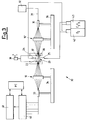
- FIG. 2 shows a section through a capsule 20 within which copenetration takes place between the cores of the interlaced fibres.
- said capsule 20 consists of two half-shells 21 and 22 of C cross-section which mate along their open perimeter.
- the fibre interlacement 23 is arranged centrally within the capsule 20, and two heating torches 24 and 25 are arranged externally to said capsule 20 in diametrically opposite positions.
- the particular shape of the capsule and the spatial arrangement of the two heat sources achieve the desirable condition that the heat flow is constant over the entire perimeter of the interlacement 23.
- the hottest points of the capsule 20 are those most distant from the interlacement whereas vice versa the coldest are the closest, and hence viewed under a larger angle.
- This construction achieves perfect temperature uniformity over the fibre interlacement 23, which is not achievable with a traditional system.
- Figure 3 shows schematically a bench 30 usable for implementing the method of the present invention.
- the fibres are deprived of their primary coating for a few centimetres and their cladding diameter is reduced by chemical attack.
- the fibres are also put under tension by the effect of weights (not shown) positioned externally to the fixing points 33 and 35.
- the interlacement 23 is formed by mutually rotating the two masking elements 10 and 10'.
- the apparatus 32 When the bench 30 has been fitted out, the apparatus 32 simultaneously generates two optical signals of different wavelengths along the central fibre of the cable 31, and the optical powers received at the exit of all the fibres are measured. At this point the torches 24 and 25 are lit and, after a preheating stage to bring the interlacement temperature to a level such as to cause the vitreous material of the fibres to soften, the movable guides 34 and 36 are operated, possibly also again mutually rotating 10 and 10', to commence the elongation and tapering stage, in which the different fibres tend to penetrate one into another to form a single body.
- the exit optical power is kept monitored by the display instrument 41, and when this optical power reaches the required value in terms of insertion loss and uniformity of the optical signal, the heating process with simultaneous elongation and twisting are suspended by halting the movement of the movable guides 34 and 36 and extinguishing the torches 24 and 25.
- the electromagnet 39 can be operated to cause the jaws 37 and 38 to open the capsule 20 by withdrawing its half-shells from each other.
- This facility for considerably increasing the cooling rate is very useful because it reduces the phenomenon of drift of the chosen point of operation, this phenomenon being due to latent inertia in the still too soft vitreous mass subjected to thermal and stress gradients.
- the method of the present invention hence also solves the problem of controlling the difference between the propagation constant of the most outer fibres and that of the inner fibres to obtain the desired spectral behaviour.
- the method of the invention eliminates any radial compression force on the outer fibres.
- the fibres do not run the risk of absorbing hydroxyl ions and hence do not present significant attenuation peaks.
- Figures 4a and 4b show the results of tests conducted on a 1x7 monomode coupler formed by the method of the present invention, charting the extent of stochastic attenuation at the two wavelengths delimiting the fibre optic signal transfer band.
- Figures 5a and 5b show for the same group of tests the divergencies between the maximum and minimum value of the signal transmitted along various fibres leaving the coupler.
- Figures 6, 7 and 8 show the the signal attenuation profile for the central optical fibre and for two chosen peripheral fibres as a function of the wavelength. It can be seen that for the two peripheral fibres (but also for the other fibres, based on results which are not illustrated) there is no peak in the intermediate region, as there would typically be for couplers formed by conventional methods.
Landscapes
- Physics & Mathematics (AREA)
- General Physics & Mathematics (AREA)
- Optics & Photonics (AREA)
- Mechanical Coupling Of Light Guides (AREA)
- Multicomponent Fibers (AREA)
- Non-Disconnectible Joints And Screw-Threaded Joints (AREA)
- Optical Fibers, Optical Fiber Cores, And Optical Fiber Bundles (AREA)
Applications Claiming Priority (2)
| Application Number | Priority Date | Filing Date | Title |
|---|---|---|---|
| ITMI940904A IT1269724B (it) | 1994-05-09 | 1994-05-09 | Procedimento per ottenere un accoppiatore monomodale monolitico a fibre fuse |
| ITMI940904 | 1994-05-09 |
Publications (1)
| Publication Number | Publication Date |
|---|---|
| EP0682275A1 true EP0682275A1 (fr) | 1995-11-15 |
Family
ID=11368856
Family Applications (1)
| Application Number | Title | Priority Date | Filing Date |
|---|---|---|---|
| EP94202229A Withdrawn EP0682275A1 (fr) | 1994-05-09 | 1994-08-02 | Méthode de fabrication d'un coupleur à fusion de fibres monomodes monolithique |
Country Status (4)
| Country | Link |
|---|---|
| EP (1) | EP0682275A1 (fr) |
| JP (1) | JPH07306331A (fr) |
| CA (1) | CA2129807A1 (fr) |
| IT (1) | IT1269724B (fr) |
Citations (5)
| Publication number | Priority date | Publication date | Assignee | Title |
|---|---|---|---|---|
| EP0171479A1 (fr) * | 1984-08-03 | 1986-02-19 | Magnetic Controls Company | Assemblage et fabrication d'un coupleur multibroche en étoile |
| EP0174014A2 (fr) * | 1984-09-06 | 1986-03-12 | Hitachi, Ltd. | Coupleur en étoile et procédé pour le fabriquer |
| EP0219096A2 (fr) * | 1985-10-16 | 1987-04-22 | Hitachi, Ltd. | Coupleur étoile à fibre optique et son procédé de fabrication |
| EP0234326A2 (fr) * | 1986-02-24 | 1987-09-02 | Allied Corporation | Coupleur de fibres optiques monomodes et son procédé de fabrication |
| DE4223176A1 (de) * | 1992-07-15 | 1994-01-20 | Sel Alcatel Ag | Vorrichtung und Verfahren zur Herstellung von optischen Sternkopplern |
-
1994
- 1994-05-09 IT ITMI940904A patent/IT1269724B/it active IP Right Grant
- 1994-08-02 EP EP94202229A patent/EP0682275A1/fr not_active Withdrawn
- 1994-08-09 CA CA002129807A patent/CA2129807A1/fr not_active Abandoned
- 1994-08-09 JP JP6206091A patent/JPH07306331A/ja active Pending
Patent Citations (5)
| Publication number | Priority date | Publication date | Assignee | Title |
|---|---|---|---|---|
| EP0171479A1 (fr) * | 1984-08-03 | 1986-02-19 | Magnetic Controls Company | Assemblage et fabrication d'un coupleur multibroche en étoile |
| EP0174014A2 (fr) * | 1984-09-06 | 1986-03-12 | Hitachi, Ltd. | Coupleur en étoile et procédé pour le fabriquer |
| EP0219096A2 (fr) * | 1985-10-16 | 1987-04-22 | Hitachi, Ltd. | Coupleur étoile à fibre optique et son procédé de fabrication |
| EP0234326A2 (fr) * | 1986-02-24 | 1987-09-02 | Allied Corporation | Coupleur de fibres optiques monomodes et son procédé de fabrication |
| DE4223176A1 (de) * | 1992-07-15 | 1994-01-20 | Sel Alcatel Ag | Vorrichtung und Verfahren zur Herstellung von optischen Sternkopplern |
Also Published As
| Publication number | Publication date |
|---|---|
| CA2129807A1 (fr) | 1995-11-10 |
| ITMI940904A1 (it) | 1995-11-09 |
| IT1269724B (it) | 1997-04-15 |
| JPH07306331A (ja) | 1995-11-21 |
| ITMI940904A0 (it) | 1994-05-09 |
Similar Documents
| Publication | Publication Date | Title |
|---|---|---|
| US5935288A (en) | Method for producing fused fiber bundles | |
| US4772085A (en) | Multimode fiber optic coupler and method for making | |
| EP0578982B1 (fr) | Coupleur à fibres optiques achtomatique et revêtu | |
| US4330170A (en) | Low-loss star couplers for optical fiber systems | |
| US5017206A (en) | Method of providing a 1xN fiber optic coupler | |
| EP0606583B1 (fr) | Coupleur achromatique pour fibres optiques | |
| US5647040A (en) | Tunable optical coupler using photosensitive glass | |
| EP0289578B1 (fr) | Fabrication de composants en fibres optiques | |
| KR0180724B1 (ko) | 염소로 도프된 광부품 및 그 제조방법 | |
| EP0628839B1 (fr) | Coupleur à faibles pertes | |
| EP0182555A2 (fr) | Procédé de fabrication d'un brouilleur de modes à fibre optique | |
| US5339374A (en) | Fused biconical taper fiber optic coupler station and fabrication techniques | |
| WO2000057220A9 (fr) | Fibre a plusieurs noyaux dilates par voie thermique | |
| US5754720A (en) | Low loss fiber optic coupler and method | |
| US4836644A (en) | Fiber optic star coupler | |
| EP0840146B1 (fr) | Procédé de fabrication des réseaux de fibre à longue période | |
| US6560388B1 (en) | Microbend fused fiber coupler method and apparatus | |
| EP0682275A1 (fr) | Méthode de fabrication d'un coupleur à fusion de fibres monomodes monolithique | |
| US6301412B1 (en) | Apparatus and method for making multi-branching optical coupler | |
| US6553791B1 (en) | Etching an optical fiber fusion splice | |
| CA1209090A (fr) | Irradiation de faisceaux de fibres de verre et de fibres optiques | |
| GB2184258A (en) | Wavelength division multiplex fused optical monomode fibre coupler | |
| JPH05297240A (ja) | スターカプラおよびその製造方法 | |
| Razak et al. | RMANCE AI\D RELIABILITY OF SINGLE MODE FUSED F'IBER COUPLERS |
Legal Events
| Date | Code | Title | Description |
|---|---|---|---|
| PUAI | Public reference made under article 153(3) epc to a published international application that has entered the european phase |
Free format text: ORIGINAL CODE: 0009012 |
|
| AK | Designated contracting states |
Kind code of ref document: A1 Designated state(s): AT CH DE ES FR GB LI NL PT SE |
|
| STAA | Information on the status of an ep patent application or granted ep patent |
Free format text: STATUS: THE APPLICATION IS DEEMED TO BE WITHDRAWN |
|
| 18D | Application deemed to be withdrawn |
Effective date: 19960516 |