EP0682431A1 - Système de réseau en anneau - Google Patents
Système de réseau en anneau Download PDFInfo
- Publication number
- EP0682431A1 EP0682431A1 EP95650014A EP95650014A EP0682431A1 EP 0682431 A1 EP0682431 A1 EP 0682431A1 EP 95650014 A EP95650014 A EP 95650014A EP 95650014 A EP95650014 A EP 95650014A EP 0682431 A1 EP0682431 A1 EP 0682431A1
- Authority
- EP
- European Patent Office
- Prior art keywords
- node
- signal
- addressee
- nodes
- return
- Prior art date
- Legal status (The legal status is an assumption and is not a legal conclusion. Google has not performed a legal analysis and makes no representation as to the accuracy of the status listed.)
- Granted
Links
- 238000004891 communication Methods 0.000 claims abstract description 20
- 238000003745 diagnosis Methods 0.000 claims abstract description 6
- 238000012546 transfer Methods 0.000 claims description 19
- 238000012545 processing Methods 0.000 claims description 14
- 238000001514 detection method Methods 0.000 claims description 6
- 238000012544 monitoring process Methods 0.000 claims description 6
- 230000004044 response Effects 0.000 abstract description 7
- 230000005540 biological transmission Effects 0.000 description 6
- 238000010276 construction Methods 0.000 description 5
- 238000000034 method Methods 0.000 description 4
- 238000011084 recovery Methods 0.000 description 3
- 238000010586 diagram Methods 0.000 description 2
- 238000009434 installation Methods 0.000 description 2
- 238000012986 modification Methods 0.000 description 2
- 230000004048 modification Effects 0.000 description 2
- 230000008569 process Effects 0.000 description 2
- 230000001052 transient effect Effects 0.000 description 2
- 238000012795 verification Methods 0.000 description 2
- 102100021259 Frizzled-1 Human genes 0.000 description 1
- 102100021265 Frizzled-2 Human genes 0.000 description 1
- 101000819438 Homo sapiens Frizzled-1 Proteins 0.000 description 1
- 101000819477 Homo sapiens Frizzled-2 Proteins 0.000 description 1
- 230000004913 activation Effects 0.000 description 1
- 230000003466 anti-cipated effect Effects 0.000 description 1
- 238000013459 approach Methods 0.000 description 1
- 125000004122 cyclic group Chemical group 0.000 description 1
- 238000013481 data capture Methods 0.000 description 1
- 238000012217 deletion Methods 0.000 description 1
- 230000037430 deletion Effects 0.000 description 1
- 230000001419 dependent effect Effects 0.000 description 1
- 230000006870 function Effects 0.000 description 1
- 230000000977 initiatory effect Effects 0.000 description 1
- 238000012423 maintenance Methods 0.000 description 1
- 230000002441 reversible effect Effects 0.000 description 1
- 230000035945 sensitivity Effects 0.000 description 1
- 230000008054 signal transmission Effects 0.000 description 1
Images

Classifications
-
- H—ELECTRICITY
- H04—ELECTRIC COMMUNICATION TECHNIQUE
- H04L—TRANSMISSION OF DIGITAL INFORMATION, e.g. TELEGRAPHIC COMMUNICATION
- H04L12/00—Data switching networks
- H04L12/28—Data switching networks characterised by path configuration, e.g. LAN [Local Area Networks] or WAN [Wide Area Networks]
- H04L12/42—Loop networks
- H04L12/423—Loop networks with centralised control, e.g. polling
-
- H—ELECTRICITY
- H04—ELECTRIC COMMUNICATION TECHNIQUE
- H04L—TRANSMISSION OF DIGITAL INFORMATION, e.g. TELEGRAPHIC COMMUNICATION
- H04L12/00—Data switching networks
- H04L12/28—Data switching networks characterised by path configuration, e.g. LAN [Local Area Networks] or WAN [Wide Area Networks]
- H04L12/42—Loop networks
- H04L12/437—Ring fault isolation or reconfiguration
Definitions
- the invention relates to a ring network system comprising:- a plurality of nodes, each comprising means for capturing data; communication links interconnecting the nodes in a ring configuration; control means in at least one sender node comprising means for transmitting an outgoing signal to an addressee node, receiving a return signal from the addressee node, and retaining captured data incorporated in the return signal; and data transfer means in each node comprising means for receiving an outgoing signal addressed to it, generating a return signal including captured data, and transmitting said return signal to the sender node.
- Examples of such systems are building management or alarm systems whereby the captured data is sensed by sensors.
- a central processor transmits signals in alternative cycles in opposite directions to nodes of the system.
- Each node is adapted to respond in a direction opposite to the direction of the command transmission. Accordingly, if a fault occurs, a command may be transmitted in the opposite direction to ensure fault tolerance.
- each node has a reversible repeater whereby the direction of the signal transmission automatically changes in a cyclic manner. Setting of the direction for each cycle is according to whether or not there is a fault in the system.
- An object is to provide a system which is flexible in operation whereby nodes may be added or deleted in a simple manner.
- a still further object is that the system be capable of handling signals of different types in a simple manner, and that the system may be spread over a large physical area.
- Another object of the invention is to provide for efficient and fast communication of data which is captured at individual nodes of a ring network system.
- control means of the sender node comprises means for: inserting a relative address in the outgoing signal, the relative address being determined according to the relative location of the addressee node in the system, and reading an addressee node identifier incorporated in the return signal; and said data transfer means comprises means for: receiving an outgoing signal, monitoring the relative address, and determining if it is the addressee node; re-transmitting the outgoing signal to a next node if it is not the addressee node; and inserting a node identifier in the return signal, and transmitting the return signal to the sender node on a return path through nodes of the system.
- sender node By virtue of the fact that a sender node does not need to know the identifier of an addressee node, very little time input is required for setting-up the system.
- the sender node can simply address each node location in turn or choose to address any node according to its location and monitor the identifier which is returned with the return signal. This leads to a large degree of flexibility.
- the data transfer means of each node comprises:- means for changing the relative address of an outgoing signal before re-transmitting it to the next node whereby the relative address is dynamically maintained; and means for determining if the node is the addressee node if the relative address has a pre-set common addressee value.
- the relative address is a count value
- the data transfer means of each node comprises means for:- receiving a signal and determining according to the count value if said signal is an outgoing signal, and determining if the node is the addressee node if the count value has a pre-set common addressee value; and if the signal is an outgoing signal and the node is not the addressee node, changing the count value in a predetermined manner and re-transmitting the signal to the next node.
- the data transfer means comprising means for changing the count value by decrementing it.
- each node changes the relative address of an outgoing signal, the relative address is always maintained with the correct relative value. For example, at any location on the system its value will indicate the relative position of the addressee node with respect to the signal location. Further, each node can immediately recognise that it is not the addressee node by simply checking for a common and fixed addressee node value so there is therefore no need for it to check for an associated unique address. This leads to fast operation of the network.
- the data transfer means comprises means for determining if a received signal is a return signal if the relative address has a pre-set common return signal value.
- the data transfer means of each node comprises means for:- determining if a received signal is a return signal and if so, adding captured data together with its identifier to the signal and re-transmitting the signal to a next node on the return path.
- a single outgoing signal transmitted from a sender node to an addressee node can result in data being captured from all of the intervening nodes. This significantly improves performance of the system, particularly where the application is a control system in which the volume of data is low but speed is important.
- control systems are alarm systems, machine control systems, lighting control systems and building control systems generally.
- control means comprises:- means for transmitting a polling signal to every node location of the system using said relative addresses; means for monitoring return signals from the nodes and reading the identifiers in said return signals; and means for updating a table in a non-volatile memory correlating node locations with identifiers, whereby automatic configuration of the system takes place.
- the or each sender node simply performs automatic configuration by addressing every node location without "knowing" the identifier of any of the nodes.
- control means comprises means for automatically performing said automatic configuration operations upon detection of a fault. For example, modification of the system by adding a node would be recognised by the or each sender node as a fault - thus initiating automatic configuration.
- the data transfer means of each node comprises means for transmitting the return signal in the opposite direction to that of the outgoing signal.
- control means comprises means for transmitting different outgoing signals in opposite directions to omit a communication link to assist in fault detection.
- control means comprises means for:- sequentially omitting communication links in order around the system in successive outgoing signal cycles; and monitoring the return signals and carrying out fault diagnosis processing based on data in said return signals.
- the sender node can gather comprehensive fault diagnosis data including patterns of minor faults. This may lead to, for example, major faults being anticipated in advance.
- said data transfer means comprises a signal repeater buffer amplifier. This allows the links between nodes to be up to 1km long - providing flexibility for installation.
- system further comprises a remote infra-red user interface, and an infrared module in each node programmed to transmit node status information to the user interface when requested. This allows a technician to easily interrogate nodes without physically accessing the circuits.
- a ring network system 1 of the invention is, in this embodiment, a control system having nodes which capture data by use of alarm sensors. This captured data must be communicated in the network.
- nodes can receive command signals which are acted upon, such as alarm re-setting conditions.
- the system 1 comprises bi-directional network links 2 which interconnect a set of nodes.
- the network 1 only has six nodes, although in practice it may have up to 256 or indeed in excess of 256 nodes.
- the nodes which are illustrated are a sender or master node M and a set of slave nodes A, B, C, D, and E. In the clockwise direction from the master node M, there are six network links 3, 4, 5, 6, 7 and 8.
- the system 1 may be spread over a wide physical area with up to 1km between nodes.
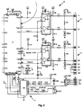
- each node comprises a data processing and communication circuit 10.
- the circuit 10 comprises a processor 11 and RS485 ports 12 and 13. Operation of each port is identical and accordingly description of the port 12 is sufficient.
- This port includes a receive terminal 1(a) and a transmit terminal 1(b) and protection diodes FZD1 and FZD2. These provide transient protection.
- a resistor combination R1/R3 provides transient and current protection.
- the resistors R8 and R11 operate to pull the signal value down if there is no signal present whereby pin 1 of a buffer amp. U1 is high if there is no signal present.
- the port 12 operates by presenting a differential voltage across R2 which appears at the pins 6 and 7 of the amp. U1 and is inputted as a signal at a processor pin RXD1.
- the processor 11 (U7) is of the Hitachi H8520 type, although any microprocessor or microcontroller having suitable i/o ports and a clock speed close to or exceeding the clock speed of U7, namely 19.6608 MHz would be suitable.
- the processor 11 operates to receive the signal via RXD1 or alternatively RXD2 and to carry out various data processing operations. It then re-transmits a signal via the buffer amp. U1 and TXD1 or TXD2 so that it acts as a repeater.
- the signal which is transmitted is via the port 12 or 13 other than that on which the signal was received. Because the buffer amplifier U1 acts as a repeater, the nodes may be up to 1km apart - thus providing a good deal of flexibility for physical installation.
- the circuit 10 also comprises a driver circuit U9.
- Other circuit components which are connected to the circuit 10 and which are not illustrated include a non-volatile memory, an infrared receiver and a reset and power control circuit.
- IR module an infrared user interface
- the manner in which an individual node communicates with the IR module is set by the master node M.
- Data is transmitted to the IR module using pulse-distance modulation.
- Null start or stop bits are required. Bits are presented by 500 microseconds of carrier at 38 kHz followed by a null carrier. The length of the null carrier determines the dibits being sent. In this way, the "on" time for the transmitting IR device is minimised, thereby maximising power efficiency.
- Each dibit is modulated by a 38 kHz carrier and every message is preceded by 9 ms of continuous carrier followed by a 4.5 pause. This is to level the internal control links and the receiver modules.
- the master node M includes other data processing and interfacing circuits for additional functions.
- the circuit 10 may be used by any node to act as a master node, particularly where fault tolerance is required and a different node is required to both transmit command signals to other nodes and to retrieve captured data for further processing.
- the processor 11 used in each node has these capabilities.
- the master node M which initiates communication sessions with other nodes. This is for retrieval of data which is captured at the nodes. However, it also has the purpose of transmitting commands to the nodes, such as a global command.
- the processor 11 in the master node M is programmed to act as a control means to transmit an outgoing signal to an addressee node of the system 1.
- the outgoing signal has a relative address which is determined according to the relative location of the addressee node in the ring network.
- the relative address is a count value, being the number of nodes which the outgoing signal must pass through, including the addressee node.
- any other suitable value could alternatively be used.
- the processor 11 of each of the nodes A to E is programmed to act in conjunction with the serial ports 12 and 13 as a data transfer means to receive and process an outgoing signal.
- the processor 11 automatically monitors the relative address and determines if it is the addressee node. This is achieved in an extremely simple manner. If the relative address count value is greater than 1, then the processor 11 immediately recognises that its node is not the addressee and therefore decrements the value of the address by 1.
- the outgoing signal is then passed on with the new relative address to the next node in the outgoing signal path. Accordingly, the relative address is dynamically maintained in real time. At each successive node, the value of the relative address is decremented by 1 until the value is a pre-set common addressee value of 1.
- a node When a node detects a relative address of this value, it knows that it is the addressee node. It then reads the data and/or commands in the outgoing signal and acts upon them.
- the outgoing signal will most often be simply a polling request for retrieval of captured data, in which case the addressee node generates a return signal which contains the captured data.
- the addressee node may therefore be referred to as an "echo node" in this context.
- the return signal is transmitted by the other of the ports 12 or 13 in the opposite direction to the outgoing signal back to the master node M.
- the relative address of the return signal is a pre-set common return signal value of 0. As each node on the return path detects that the value is 0, it knows that the signal is a return signal and passes onto the next node in the return path without changing the relative address.
- the addressee node When generating the return signal, the addressee node includes a unique node identifier so that the master node M knows the source of the return signal. As the return signal passes through each node on the return path, each node may add captured data together with its unique identifier onto a data stream part of the return signal.
- the processor 11 simply detects which port 12 or 13 the signal was received on and immediately decrements the count value, if appropriate, and re-transmits the signal.
- the delay may be 1 byte if the relative address contains only a 1 byte count value.
- the relative address may also include an inverse byte for verification purposes so that each processor 11 can discriminate noise.
- the system is to include more than 256 nodes, there may be 4 bytes, 2 count value bytes and 2 inverse bytes. Of course, if the clock speed of the nodes is extremely high, it may not be necessary to route the signals so quickly.
- the master node M does not need to know the unique identifier when generating an outgoing signal - it just specifies the node location.
- the relative address is not an address in the conventional sense as it is not the address of a node - it instead governs how many nodes the signal should pass through before a node determines that it is the addressee.
- the master node can operate to automatically update a table in non-volatile memory which correlates node locations with identifiers by polling every node location and logging the identifier in the return signal. This leads to enormous flexibility as nodes may be easily added or deleted - the master node performing automatic configuration. Accordingly, the installer just connects the node at the desired location and ensures that it has a programmed identifier.
- an outgoing signal O.S.1 is transmitted in the clockwise direction from the master node M.
- This signal traverses the communication links 3, 4 and 5 via the nodes E and D until it reaches the addressee node C.
- the relative address will have a count value of decimal 3 which is decremented to decimal 2 by the node E and decremented to decimal 1 by the node D.
- the node C receives the outgoing signal O.S.1, it detects that the relative address has a value of decimal 1 and therefore knows that it is the addressee node.
- the node C therefore processes the signal and generates a return signal R.S.1 containing its identifier and the relevant return information.
- the outgoing signal O.S.1 may include commands instructing the node C in some aspect of its operation such as setting alarm threshold levels.
- the master node M receives the return signal R.S.1, it knows that the outgoing signal has been acted upon by the node C and can register this fact. It then proceeds in the next cycle to transmit an outgoing signal O.S.2 in the anti-clockwise direction through the communication links 8 and 7 and the node A.
- the relative address has a value decimal 2 which is decremented to decimal 1 by the node A and therefore the node B recognises the fact that it is the addressee node. It generates a return signal R.S.2 on the return path through the communication links 7 and 8 and the node A.
- the communication link 6 has been omitted in this full cycle of outgoing signals O.S.1 and O.S.2.
- the master node M omits the next link 7 by issuing two outgoing signals in opposite directions with the nodes A and B as being the two addressee or echo nodes. It operates in sequence to omit each communication link in turn.
- the master node M is programmed to monitor the return signals and to record a diagnosis history of faults arising in the return signals. It can therefore establish in memory a pattern of faults and relate this pattern to individual communication links for fault diagnosis and generation of fault reports. In this way, the master node M may in the course of its normal operation, gather together enough information for location of intermittent faults. Intermittent faults are the most difficult to detect in network systems.
- the nodes D and C are automatically set to be the addressee nodes for the respective outgoing signal directions. In this way, all nodes are accessed despite the fact that there is a fault.
- the master node M is programmed to generate an error output at its interface to indicate the fault location. Another feature of the master node M is that is performs automatic configuration operations immediately upon detection of a fault to check if addition or deletion of a node is the reason for the fault. When a fault is signalled, a maintenance person can easily interrogate suspected nodes using the IR module and thus very quickly identify a physical fault location. This is very important for complex systems.
- the processor 11 of each node is programmed to add captured data onto a return signal which passes through the node. Accordingly, immediately when the processor 11 detects that the relative address count value is 0, it adds its captured data to the data stream of the return signal before re-transmitting it to the next node on the return path. Therefore, in the cycles shown in Fig. 1(a), the return signal R.S.1 retrieves data from the nodes C, D, and E. Similarly, the return signal R.S.2 includes data captured at the nodes B and A. This is very important in providing for a high-speed operation of the system 1 in that a single outgoing signal results in return of data from all nodes between the sender node and the addressee node.
- the master node M may specify in a destination group address (DGA) field of the outgoing signal which intervening nodes may add captured data.
- DGA destination group address
- the outgoing signal need not necessarily be for retrieval of captured data. It may include commands from the master node M or indeed, from any other sender node.
- the outgoing signal may be a global command signal which is acted upon by all nodes, or alternatively, it may be specific to a particular addressee node, addressing being carried out as described above. Examples of a global command signal may be a signal for synchronisation of clocks or alternatively activation of alarm output devices.
- the return signal may indicate errors which arise when the node attempts to act in response to the command signal.
- the relative address is used as described above, however, the DGA field may specify that intervening nodes should act upon the commands also.
- the nodes of the system will operate at 0-5 V signal levels with receiver input impedance of at least 12 K Ohms, input sensitivity of at least +/- 200 mV and input hysteresis of 5 mV.
- the receiver common node range is -7 V to +12 V at a minimum.
- the transmitter section can supply a minimum of 20 mA to the communication lines via the ports 12 and 13 so that it acts as a repeater and is capable of operation at up to 307200 baud.
- the processors 11 in the various nodes are programmed to transmit the outgoing and return signals as described above using the relevant ports 12 and 13. Where a signal comes in at one port, it is sent out on the relevant transmit line on the other port, and vice versa. Regarding the manner in which the processors 11 are programmed to generate the relevant structures, the following describes this in more detail.
- the following is the format for an outgoing signal:- ⁇ rel> ⁇ irel> ⁇ dly> ⁇ key> ⁇ cks> ⁇ DGA> ⁇ seq> ⁇ type> ⁇ len> ⁇ data> ⁇ cks>
- the ⁇ rel> ⁇ irel> ⁇ dly> ⁇ key> ⁇ cks> string forms a header for the outgoing signal.
- the remainder may be regarded as a control frame.
- the return signal has a header similar to that of the outgoing signal, the relative address ⁇ rel> having a fixed value of 0.
- the following is the format of the information frame which follows the header:- ⁇ ser> ⁇ type> ⁇ len> ⁇ data> ⁇ cks>
- the ⁇ DGA> field controls the extent of data retrieval in a simple manner.
- the ⁇ irel> field and its dynamic updating help to provide for immediate error ⁇ noise detection.
- the ⁇ dly> field helps to ensure data may be retrieved from all required nodes.
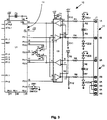
- FIG. 3 an alternative construction of processing and communication circuit 20 for nodes of a system of the invention is illustrated.
- This is a simpler embodiment having a processor 21 or U1 which is of the Intel 8052TM type.
- RS232 ports 22 and 23 are connected to serial port pins on the processor 21 in which the direction is determined by a circuit (U4) and avoids the need for separate dedicated serial ports as in the first-described embodiment.
- the circuit 20 is not as good at discriminating noise when it appears at one input port while a signal is being received at the other, it is very effective for lower-cost systems as the processor 21 is simpler and less expensive than the processor 11 of the first embodiment.
- the return signal is terminated with a single 0 Byte so that the successive nodes on the return path can identify the end of the information frame.
- the 0 Byte is appended by the addressee node.
- Such a Byte is not required in the first embodiment by the processor 11 as this has a greater data processing capability.
- the invention provides for very easy configuration and modification of a ring network. This is because the master node does not need to know the identifier of a new node which is added. All that is required is for the new node to be programmed with this identifier and for it to be installed in the network. The master node may then perform automatic configuration by polling all nodes and retrieving their identifiers and storing these. The important point is that the master node does not need to include any identifiers in its outgoing signals. By virtue of the fact that each node in turn decrements the relative address, this address is always relevant as it indicates at any time the relevant position of the addressee node with respect to the latest node which it has passed through.
- the relative address is dynamically maintained. Further, because each node in turn is only checked to see if the relative address has a fixed addressee value (1 in the embodiments described), the reading and decrementing operations may be carried out very quickly. These operations are also quite simple and accordingly there is no need for each node to have complex circuitry. Speed of retrieval of data which is captured at the various nodes is also considerably enhanced by the fact that the return signal has captured data added to its data stream on the return path. Therefore, data can be retrieved from all desired nodes between the sender and addressee nodes in response to a single outgoing signal. Because the buffer amp. Ul effectively repeats the signal by restoring it to its correct format, the network may be used over a large physical area and indeed there may be up to 1 km between each node.
- the invention is not limited to the embodiments hereinbefore described.
- any suitable data processing circuit may be used, depending on the nature of the processing required.
- the invention is primarily directed to control systems such as alarm, building management, or lighting control systems, it is also envisaged that it may be used for more intensive data processing applications.
Landscapes
- Engineering & Computer Science (AREA)
- Computer Networks & Wireless Communication (AREA)
- Signal Processing (AREA)
- Small-Scale Networks (AREA)
- Stabilization Of Oscillater, Synchronisation, Frequency Synthesizers (AREA)
Applications Claiming Priority (2)
| Application Number | Priority Date | Filing Date | Title |
|---|---|---|---|
| IE940380 | 1994-05-09 | ||
| IE940380 | 1994-05-09 |
Publications (2)
| Publication Number | Publication Date |
|---|---|
| EP0682431A1 true EP0682431A1 (fr) | 1995-11-15 |
| EP0682431B1 EP0682431B1 (fr) | 2002-10-02 |
Family
ID=11040388
Family Applications (1)
| Application Number | Title | Priority Date | Filing Date |
|---|---|---|---|
| EP95650014A Expired - Lifetime EP0682431B1 (fr) | 1994-05-09 | 1995-05-09 | Système de réseau en anneau |
Country Status (5)
| Country | Link |
|---|---|
| US (1) | US5920267A (fr) |
| EP (1) | EP0682431B1 (fr) |
| AT (1) | ATE225585T1 (fr) |
| CA (1) | CA2149005A1 (fr) |
| DE (1) | DE69528413D1 (fr) |
Cited By (6)
| Publication number | Priority date | Publication date | Assignee | Title |
|---|---|---|---|---|
| FR2771877A1 (fr) * | 1997-12-02 | 1999-06-04 | Ind De Construction D App Et R | Reseau de terrain a haute securite et disponibilite |
| WO2000029717A3 (fr) * | 1998-11-17 | 2000-09-08 | Schlumberger Technology Corp | Systeme de communications comportant des canaux redondants |
| RU2158691C1 (ru) * | 2000-02-07 | 2000-11-10 | Закрытое акционерное общество "Информтехника и Связь" | Способ диспетчерского управления на железнодорожном транспорте |
| WO2002058337A1 (fr) * | 2001-01-19 | 2002-07-25 | Openwave Systems, Inc. | Solution de reseau informatique et logiciel destines a etablir une tolerance d'erreur dans un environnement reseau |
| DE19912977B4 (de) * | 1999-03-23 | 2011-04-21 | GM Global Technology Operations, Inc., Detroit | Vorrichtung und Verfahren zur Bestimmung einfacher Leitungsstörungen in bidirektional betriebenen Netzwerken von Kraftfahrzeugen |
| WO2018215297A1 (fr) * | 2017-05-24 | 2018-11-29 | Wago Verwaltungsgesellschaft Mbh | Détermination d'abonnés de bus de données d'un bus local |
Families Citing this family (42)
| Publication number | Priority date | Publication date | Assignee | Title |
|---|---|---|---|---|
| JPH0962741A (ja) * | 1995-08-25 | 1997-03-07 | Casio Comput Co Ltd | データ通信システムにおけるデータ処理方法 |
| US6091705A (en) | 1996-12-20 | 2000-07-18 | Sebring Systems, Inc. | Method and apparatus for a fault tolerant, software transparent and high data integrity extension to a backplane bus or interconnect |
| US6581126B1 (en) | 1996-12-20 | 2003-06-17 | Plx Technology, Inc. | Method, system and apparatus for a computer subsystem interconnection using a chain of bus repeaters |
| JP3609599B2 (ja) * | 1998-01-30 | 2005-01-12 | 富士通株式会社 | ノード代理システム、ノード監視システム、それらの方法、及び記録媒体 |
| US6166653A (en) | 1998-08-13 | 2000-12-26 | Motorola Inc | System for address initialization of generic nodes in a distributed command and control system and method therefor |
| US6539450B1 (en) | 1998-11-29 | 2003-03-25 | Sony Corporation | Method and system for adjusting isochronous bandwidths on a bus |
| US7058024B1 (en) * | 1999-02-03 | 2006-06-06 | Lucent Technologies, Inc. | Automatic telecommunications link identification system |
| US6631415B1 (en) | 1999-03-19 | 2003-10-07 | Sony Corporation | Method and system for providing a communication connection using stream identifiers |
| US6810452B1 (en) | 1999-03-19 | 2004-10-26 | Sony Corporation | Method and system for quarantine during bus topology configuration |
| US6374316B1 (en) * | 1999-03-19 | 2002-04-16 | Sony Corporation | Method and system for circumscribing a topology to form ring structures |
| DE19916894B4 (de) * | 1999-04-14 | 2005-09-08 | Siemens Ag | Bussystem |
| US6502158B1 (en) | 1999-04-23 | 2002-12-31 | Sony Corporation | Method and system for address spaces |
| US6335933B1 (en) * | 1999-05-21 | 2002-01-01 | Broadcom Homenetworking, Inc. | Limited automatic repeat request protocol for frame-based communication channels |
| US6728821B1 (en) | 1999-11-29 | 2004-04-27 | Sony Corporation | Method and system for adjusting isochronous bandwidths on a bus |
| US6647446B1 (en) | 2000-03-18 | 2003-11-11 | Sony Corporation | Method and system for using a new bus identifier resulting from a bus topology change |
| EP1314277A4 (fr) * | 2000-04-17 | 2009-07-22 | Adaptive Networks Inc | Reseau de communication sur ligne de transport de force |
| US6757773B1 (en) | 2000-06-30 | 2004-06-29 | Sony Corporation | System and method for determining support capability of a device coupled to a bus system |
| US20020080807A1 (en) * | 2000-12-22 | 2002-06-27 | Lind Carina Maria | Systems and methods for queue-responsible node designation and queue-handling in an IP network |
| FR2824215B1 (fr) * | 2001-04-27 | 2003-07-18 | Canon Kk | Procede et dispositif de traitement d'un message dans un reseau de communication |
| GB0112017D0 (en) | 2001-05-17 | 2001-07-11 | Koninkl Philips Electronics Nv | Wireless master-slave distributed communications network |
| US6973049B2 (en) * | 2001-10-16 | 2005-12-06 | Corrigent Systems Ltd. | Auto-configuration of network interfaces in a bidirectional ring network |
| JP3808793B2 (ja) * | 2002-03-28 | 2006-08-16 | 東芝キヤリア株式会社 | ネットワークにおけるアドレス決定方法およびノード |
| EP1457847A3 (fr) * | 2003-03-10 | 2010-01-13 | Heidelberger Druckmaschinen Aktiengesellschaft | Système et méthode pour l'identification de modules dans une machine d'impression |
| EP1698113A2 (fr) * | 2003-11-19 | 2006-09-06 | Honeywell International, Inc. | Gardien de bus du gardien du frere en mode asynchrone pour reseaux annulaires |
| US7437595B2 (en) * | 2005-02-07 | 2008-10-14 | International Business Machines Corporation | Row fault detection system |
| US7529963B2 (en) * | 2005-02-07 | 2009-05-05 | International Business Machines Corporation | Cell boundary fault detection system |
| US7451342B2 (en) * | 2005-02-07 | 2008-11-11 | International Business Machines Corporation | Bisectional fault detection system |
| US7506197B2 (en) * | 2005-02-07 | 2009-03-17 | International Business Machines Corporation | Multi-directional fault detection system |
| US7826379B2 (en) * | 2005-02-07 | 2010-11-02 | International Business Machines Corporation | All-to-all sequenced fault detection system |
| US8495411B2 (en) * | 2005-02-07 | 2013-07-23 | International Business Machines Corporation | All row, planar fault detection system |
| US20070201867A1 (en) * | 2006-02-28 | 2007-08-30 | Tellabs Petaluma, Inc. | Method, apparatus, system and computer program product for identifying failing or failed optical network terminal(s) on an optical distribution network |
| US7668084B2 (en) * | 2006-09-29 | 2010-02-23 | Honeywell International Inc. | Systems and methods for fault-tolerant high integrity data propagation using a half-duplex braided ring network |
| US7889683B2 (en) * | 2006-11-03 | 2011-02-15 | Honeywell International Inc. | Non-destructive media access resolution for asynchronous traffic in a half-duplex braided-ring |
| US7656881B2 (en) * | 2006-12-13 | 2010-02-02 | Honeywell International Inc. | Methods for expedited start-up and clique aggregation using self-checking node pairs on a ring network |
| US7912094B2 (en) * | 2006-12-13 | 2011-03-22 | Honeywell International Inc. | Self-checking pair-based master/follower clock synchronization |
| US7778159B2 (en) * | 2007-09-27 | 2010-08-17 | Honeywell International Inc. | High-integrity self-test in a network having a braided-ring topology |
| WO2011011915A1 (fr) * | 2009-07-29 | 2011-02-03 | 华为技术有限公司 | Procédé de communication de données, équipement de communication et système de communication |
| US8320282B2 (en) * | 2009-07-30 | 2012-11-27 | Calix, Inc. | Automatic control node selection in ring networks |
| TWI427972B (zh) * | 2010-10-26 | 2014-02-21 | Accton Technology Corp | 建立路徑資訊之網路裝置及其方法 |
| JP5968119B2 (ja) * | 2012-06-27 | 2016-08-10 | キヤノン株式会社 | カスケード接続による通信システム |
| US20140223048A1 (en) * | 2013-02-06 | 2014-08-07 | Infineon Technologies Ag | Communication network and method for communicating in a communication network |
| US10884451B2 (en) * | 2018-05-01 | 2021-01-05 | DeGirum Corporation | System and methods for completing a cascaded clock ring bus |
Citations (3)
| Publication number | Priority date | Publication date | Assignee | Title |
|---|---|---|---|---|
| DE3815779A1 (de) * | 1987-07-16 | 1989-01-26 | Werkzeugmasch Heckert Veb | Verfahren und schaltungsanordnung zur leitungssparenden stoersicheren uebertragung von zustandsinformationen peripherer einrichtungen an steuerungssystemen mit einer speicherprogrammierbaren steuerung |
| DE3838152A1 (de) * | 1988-11-10 | 1990-05-31 | Kloeckner Moeller Elektrizit | Verfahren und identifizierung von busteilnehmern |
| EP0549992A1 (fr) * | 1991-12-31 | 1993-07-07 | SMH Management Services AG | Réseau informatique en anneau et procédure de transmission d'informations dans ce réseau |
Family Cites Families (7)
| Publication number | Priority date | Publication date | Assignee | Title |
|---|---|---|---|---|
| GB2064919B (en) * | 1979-12-04 | 1983-10-05 | Standard Telephones Cables Ltd | Data transmission loops optical repeaters |
| EP0214476B1 (fr) * | 1985-09-11 | 1991-06-26 | Siemens Aktiengesellschaft | Procédé et disposition pour transmettre des signaux de données entre deux dispositifs de commande appartenant à un système en anneau |
| US5049871A (en) * | 1987-01-20 | 1991-09-17 | American Magnetics Corporation | Loop communication system |
| US5140586A (en) * | 1988-01-26 | 1992-08-18 | E-Systems, Inc. | Token associated data network communications protocol |
| AU622208B2 (en) * | 1988-08-12 | 1992-04-02 | Digital Equipment Corporation | Frame removal mechanism for token ring networks |
| US4982400A (en) * | 1988-12-29 | 1991-01-01 | Intel Corporation | Ring bus hub for a star local area network |
| US5179548A (en) * | 1991-06-27 | 1993-01-12 | Bell Communications Research, Inc. | Self-healing bidirectional logical-ring network using crossconnects |
-
1995
- 1995-05-09 AT AT95650014T patent/ATE225585T1/de not_active IP Right Cessation
- 1995-05-09 EP EP95650014A patent/EP0682431B1/fr not_active Expired - Lifetime
- 1995-05-09 CA CA002149005A patent/CA2149005A1/fr not_active Abandoned
- 1995-05-09 DE DE69528413T patent/DE69528413D1/de not_active Expired - Lifetime
-
1998
- 1998-01-26 US US09/013,467 patent/US5920267A/en not_active Expired - Lifetime
Patent Citations (3)
| Publication number | Priority date | Publication date | Assignee | Title |
|---|---|---|---|---|
| DE3815779A1 (de) * | 1987-07-16 | 1989-01-26 | Werkzeugmasch Heckert Veb | Verfahren und schaltungsanordnung zur leitungssparenden stoersicheren uebertragung von zustandsinformationen peripherer einrichtungen an steuerungssystemen mit einer speicherprogrammierbaren steuerung |
| DE3838152A1 (de) * | 1988-11-10 | 1990-05-31 | Kloeckner Moeller Elektrizit | Verfahren und identifizierung von busteilnehmern |
| EP0549992A1 (fr) * | 1991-12-31 | 1993-07-07 | SMH Management Services AG | Réseau informatique en anneau et procédure de transmission d'informations dans ce réseau |
Non-Patent Citations (1)
| Title |
|---|
| A. X. WIDMER: "TOPOGRAPHICAL ADRESSING ON LOOPS", IBM TECHNICAL DISCLOSURE BULLETIN., vol. 15, no. 2, July 1972 (1972-07-01), NEW YORK US, pages 380 - 382 * |
Cited By (12)
| Publication number | Priority date | Publication date | Assignee | Title |
|---|---|---|---|---|
| FR2771877A1 (fr) * | 1997-12-02 | 1999-06-04 | Ind De Construction D App Et R | Reseau de terrain a haute securite et disponibilite |
| WO1999029070A1 (fr) * | 1997-12-02 | 1999-06-10 | Icare (S.A.) | Reseau de terrain a haute securite et disponibilite |
| WO2000029717A3 (fr) * | 1998-11-17 | 2000-09-08 | Schlumberger Technology Corp | Systeme de communications comportant des canaux redondants |
| GB2361494A (en) * | 1998-11-17 | 2001-10-24 | Schlumberger Technology Corp | Communications system having redundant channels |
| GB2361494B (en) * | 1998-11-17 | 2003-01-22 | Schlumberger Technology Corp | Communications system having redundant channels |
| US6816082B1 (en) | 1998-11-17 | 2004-11-09 | Schlumberger Technology Corporation | Communications system having redundant channels |
| DE19912977B4 (de) * | 1999-03-23 | 2011-04-21 | GM Global Technology Operations, Inc., Detroit | Vorrichtung und Verfahren zur Bestimmung einfacher Leitungsstörungen in bidirektional betriebenen Netzwerken von Kraftfahrzeugen |
| RU2158691C1 (ru) * | 2000-02-07 | 2000-11-10 | Закрытое акционерное общество "Информтехника и Связь" | Способ диспетчерского управления на железнодорожном транспорте |
| WO2002058337A1 (fr) * | 2001-01-19 | 2002-07-25 | Openwave Systems, Inc. | Solution de reseau informatique et logiciel destines a etablir une tolerance d'erreur dans un environnement reseau |
| WO2018215297A1 (fr) * | 2017-05-24 | 2018-11-29 | Wago Verwaltungsgesellschaft Mbh | Détermination d'abonnés de bus de données d'un bus local |
| US11442736B2 (en) | 2017-05-24 | 2022-09-13 | Wago Verwaltungsgesellschaft Mbh | Determination of data bus subscribers of a local bus |
| DE102017208830B4 (de) | 2017-05-24 | 2026-02-26 | Wago Verwaltungsgesellschaft Mbh | Bestimmung von Datenbusteilnehmern eines Lokalbusses |
Also Published As
| Publication number | Publication date |
|---|---|
| US5920267A (en) | 1999-07-06 |
| EP0682431B1 (fr) | 2002-10-02 |
| DE69528413D1 (de) | 2002-11-07 |
| CA2149005A1 (fr) | 1995-11-10 |
| ATE225585T1 (de) | 2002-10-15 |
Similar Documents
| Publication | Publication Date | Title |
|---|---|---|
| EP0682431B1 (fr) | Système de réseau en anneau | |
| US4980913A (en) | Security system network | |
| US5001755A (en) | Security system network | |
| KR100605208B1 (ko) | 네트워크 디바이스의 채널 핸들링 장치 | |
| KR100559025B1 (ko) | 홈 네트워크 관리 시스템 | |
| JPH0234059A (ja) | ノード装置の処理方式 | |
| US5166678A (en) | Dual master implied token communication system | |
| JP3123417B2 (ja) | 小規模ネットワークにおける通信方法及び同通信方法に適用される制御装置と従属装置 | |
| KR20040104321A (ko) | 홈 네트워크 시스템 | |
| AU645999B2 (en) | Networks | |
| US6665275B1 (en) | Network device including automatic detection of duplex mismatch | |
| US4994788A (en) | System for collecting alarms from a set of stations | |
| CN101300534B (zh) | 用于传输周期性和非周期性数据的方法和系统 | |
| US4509117A (en) | Communications network access rights arbitration | |
| US6393020B1 (en) | Gated multi-drop communication system | |
| GB2289394A (en) | A ring network system | |
| US8130636B2 (en) | Communication control system | |
| EP0093578B1 (fr) | Système de communication | |
| IES65852B2 (en) | A ring network system | |
| IE950329A1 (en) | A ring network system | |
| CN116383115A (zh) | 一种数据通信方法及系统 | |
| JPH0527821A (ja) | 単方向通信リンクの障害検出方法 | |
| JPH03267845A (ja) | データ伝送システム | |
| JPH11127185A (ja) | リアルタイム経路情報監視方法 | |
| Merz et al. | BACnet |
Legal Events
| Date | Code | Title | Description |
|---|---|---|---|
| PUAI | Public reference made under article 153(3) epc to a published international application that has entered the european phase |
Free format text: ORIGINAL CODE: 0009012 |
|
| AK | Designated contracting states |
Kind code of ref document: A1 Designated state(s): AT BE DE DK ES FR IT NL PT SE Kind code of ref document: A1 Designated state(s): AT BE DE DK ES FR GB IE IT NL PT SE |
|
| 17P | Request for examination filed |
Effective date: 19960104 |
|
| 17Q | First examination report despatched |
Effective date: 20000714 |
|
| GRAG | Despatch of communication of intention to grant |
Free format text: ORIGINAL CODE: EPIDOS AGRA |
|
| GRAG | Despatch of communication of intention to grant |
Free format text: ORIGINAL CODE: EPIDOS AGRA |
|
| GRAH | Despatch of communication of intention to grant a patent |
Free format text: ORIGINAL CODE: EPIDOS IGRA |
|
| RBV | Designated contracting states (corrected) |
Designated state(s): AT BE DE DK ES FR IT NL PT SE |
|
| GRAH | Despatch of communication of intention to grant a patent |
Free format text: ORIGINAL CODE: EPIDOS IGRA |
|
| GRAA | (expected) grant |
Free format text: ORIGINAL CODE: 0009210 |
|
| AK | Designated contracting states |
Kind code of ref document: B1 Designated state(s): AT BE DE DK ES FR IT NL PT SE |
|
| PG25 | Lapsed in a contracting state [announced via postgrant information from national office to epo] |
Ref country code: NL Free format text: LAPSE BECAUSE OF FAILURE TO SUBMIT A TRANSLATION OF THE DESCRIPTION OR TO PAY THE FEE WITHIN THE PRESCRIBED TIME-LIMIT Effective date: 20021002 Ref country code: IT Free format text: LAPSE BECAUSE OF FAILURE TO SUBMIT A TRANSLATION OF THE DESCRIPTION OR TO PAY THE FEE WITHIN THE PRESCRIBED TIME-LIMIT;WARNING: LAPSES OF ITALIAN PATENTS WITH EFFECTIVE DATE BEFORE 2007 MAY HAVE OCCURRED AT ANY TIME BEFORE 2007. THE CORRECT EFFECTIVE DATE MAY BE DIFFERENT FROM THE ONE RECORDED. Effective date: 20021002 Ref country code: FR Free format text: LAPSE BECAUSE OF FAILURE TO SUBMIT A TRANSLATION OF THE DESCRIPTION OR TO PAY THE FEE WITHIN THE PRESCRIBED TIME-LIMIT Effective date: 20021002 Ref country code: BE Free format text: LAPSE BECAUSE OF FAILURE TO SUBMIT A TRANSLATION OF THE DESCRIPTION OR TO PAY THE FEE WITHIN THE PRESCRIBED TIME-LIMIT Effective date: 20021002 Ref country code: AT Free format text: LAPSE BECAUSE OF FAILURE TO SUBMIT A TRANSLATION OF THE DESCRIPTION OR TO PAY THE FEE WITHIN THE PRESCRIBED TIME-LIMIT Effective date: 20021002 |
|
| REF | Corresponds to: |
Ref document number: 225585 Country of ref document: AT Date of ref document: 20021015 Kind code of ref document: T |
|
| REF | Corresponds to: |
Ref document number: 69528413 Country of ref document: DE Date of ref document: 20021107 |
|
| PG25 | Lapsed in a contracting state [announced via postgrant information from national office to epo] |
Ref country code: SE Free format text: LAPSE BECAUSE OF FAILURE TO SUBMIT A TRANSLATION OF THE DESCRIPTION OR TO PAY THE FEE WITHIN THE PRESCRIBED TIME-LIMIT Effective date: 20030102 Ref country code: PT Free format text: LAPSE BECAUSE OF FAILURE TO SUBMIT A TRANSLATION OF THE DESCRIPTION OR TO PAY THE FEE WITHIN THE PRESCRIBED TIME-LIMIT Effective date: 20030102 Ref country code: DK Free format text: LAPSE BECAUSE OF FAILURE TO SUBMIT A TRANSLATION OF THE DESCRIPTION OR TO PAY THE FEE WITHIN THE PRESCRIBED TIME-LIMIT Effective date: 20030102 |
|
| PG25 | Lapsed in a contracting state [announced via postgrant information from national office to epo] |
Ref country code: DE Free format text: LAPSE BECAUSE OF FAILURE TO SUBMIT A TRANSLATION OF THE DESCRIPTION OR TO PAY THE FEE WITHIN THE PRESCRIBED TIME-LIMIT Effective date: 20030103 |
|
| NLV1 | Nl: lapsed or annulled due to failure to fulfill the requirements of art. 29p and 29m of the patents act | ||
| PG25 | Lapsed in a contracting state [announced via postgrant information from national office to epo] |
Ref country code: ES Free format text: LAPSE BECAUSE OF FAILURE TO SUBMIT A TRANSLATION OF THE DESCRIPTION OR TO PAY THE FEE WITHIN THE PRESCRIBED TIME-LIMIT Effective date: 20030429 |
|
| EN | Fr: translation not filed | ||
| PLBE | No opposition filed within time limit |
Free format text: ORIGINAL CODE: 0009261 |
|
| STAA | Information on the status of an ep patent application or granted ep patent |
Free format text: STATUS: NO OPPOSITION FILED WITHIN TIME LIMIT |
|
| 26N | No opposition filed |
Effective date: 20030703 |