EP0682586B1 - Outil de fabrication de couronnes dentees - Google Patents
Outil de fabrication de couronnes dentees Download PDFInfo
- Publication number
- EP0682586B1 EP0682586B1 EP94907015A EP94907015A EP0682586B1 EP 0682586 B1 EP0682586 B1 EP 0682586B1 EP 94907015 A EP94907015 A EP 94907015A EP 94907015 A EP94907015 A EP 94907015A EP 0682586 B1 EP0682586 B1 EP 0682586B1
- Authority
- EP
- European Patent Office
- Prior art keywords
- tool
- profile
- tangent
- base circle
- involute
- Prior art date
- Legal status (The legal status is an assumption and is not a legal conclusion. Google has not performed a legal analysis and makes no representation as to the accuracy of the status listed.)
- Expired - Lifetime
Links
- 238000004519 manufacturing process Methods 0.000 title claims abstract description 9
- 238000003754 machining Methods 0.000 claims abstract description 26
- 238000005520 cutting process Methods 0.000 claims abstract description 17
- 238000000034 method Methods 0.000 claims abstract description 4
- 239000013598 vector Substances 0.000 claims description 8
- 238000000227 grinding Methods 0.000 claims description 4
- 238000003801 milling Methods 0.000 claims description 4
- 239000002245 particle Substances 0.000 claims 1
- 239000000463 material Substances 0.000 description 2
- 230000036346 tooth eruption Effects 0.000 description 2
- 230000002411 adverse Effects 0.000 description 1
- 230000000694 effects Effects 0.000 description 1
- 238000004904 shortening Methods 0.000 description 1
Images


Classifications
-
- B—PERFORMING OPERATIONS; TRANSPORTING
- B23—MACHINE TOOLS; METAL-WORKING NOT OTHERWISE PROVIDED FOR
- B23F—MAKING GEARS OR TOOTHED RACKS
- B23F15/00—Methods or machines for making gear wheels of special kinds not covered by groups B23F7/00 - B23F13/00
- B23F15/06—Making gear teeth on the front surface of wheels, e.g. for clutches or couplings with toothed faces
-
- B—PERFORMING OPERATIONS; TRANSPORTING
- B23—MACHINE TOOLS; METAL-WORKING NOT OTHERWISE PROVIDED FOR
- B23F—MAKING GEARS OR TOOTHED RACKS
- B23F21/00—Tools specially adapted for use in machines for manufacturing gear teeth
- B23F21/02—Grinding discs; Grinding worms
- B23F21/026—Grinding worms
-
- B—PERFORMING OPERATIONS; TRANSPORTING
- B23—MACHINE TOOLS; METAL-WORKING NOT OTHERWISE PROVIDED FOR
- B23F—MAKING GEARS OR TOOTHED RACKS
- B23F21/00—Tools specially adapted for use in machines for manufacturing gear teeth
- B23F21/12—Milling tools
- B23F21/16—Hobs
-
- Y—GENERAL TAGGING OF NEW TECHNOLOGICAL DEVELOPMENTS; GENERAL TAGGING OF CROSS-SECTIONAL TECHNOLOGIES SPANNING OVER SEVERAL SECTIONS OF THE IPC; TECHNICAL SUBJECTS COVERED BY FORMER USPC CROSS-REFERENCE ART COLLECTIONS [XRACs] AND DIGESTS
- Y10—TECHNICAL SUBJECTS COVERED BY FORMER USPC
- Y10T—TECHNICAL SUBJECTS COVERED BY FORMER US CLASSIFICATION
- Y10T407/00—Cutters, for shaping
- Y10T407/17—Gear cutting tool
- Y10T407/1715—Hob
-
- Y—GENERAL TAGGING OF NEW TECHNOLOGICAL DEVELOPMENTS; GENERAL TAGGING OF CROSS-SECTIONAL TECHNOLOGIES SPANNING OVER SEVERAL SECTIONS OF THE IPC; TECHNICAL SUBJECTS COVERED BY FORMER USPC CROSS-REFERENCE ART COLLECTIONS [XRACs] AND DIGESTS
- Y10—TECHNICAL SUBJECTS COVERED BY FORMER USPC
- Y10T—TECHNICAL SUBJECTS COVERED BY FORMER US CLASSIFICATION
- Y10T407/00—Cutters, for shaping
- Y10T407/17—Gear cutting tool
- Y10T407/1715—Hob
- Y10T407/172—Thread cutting
-
- Y—GENERAL TAGGING OF NEW TECHNOLOGICAL DEVELOPMENTS; GENERAL TAGGING OF CROSS-SECTIONAL TECHNOLOGIES SPANNING OVER SEVERAL SECTIONS OF THE IPC; TECHNICAL SUBJECTS COVERED BY FORMER USPC CROSS-REFERENCE ART COLLECTIONS [XRACs] AND DIGESTS
- Y10—TECHNICAL SUBJECTS COVERED BY FORMER USPC
- Y10T—TECHNICAL SUBJECTS COVERED BY FORMER US CLASSIFICATION
- Y10T407/00—Cutters, for shaping
- Y10T407/17—Gear cutting tool
- Y10T407/1745—Rotary, tooth form cutting tool
-
- Y—GENERAL TAGGING OF NEW TECHNOLOGICAL DEVELOPMENTS; GENERAL TAGGING OF CROSS-SECTIONAL TECHNOLOGIES SPANNING OVER SEVERAL SECTIONS OF THE IPC; TECHNICAL SUBJECTS COVERED BY FORMER USPC CROSS-REFERENCE ART COLLECTIONS [XRACs] AND DIGESTS
- Y10—TECHNICAL SUBJECTS COVERED BY FORMER USPC
- Y10T—TECHNICAL SUBJECTS COVERED BY FORMER US CLASSIFICATION
- Y10T409/00—Gear cutting, milling, or planing
- Y10T409/10—Gear cutting
- Y10T409/101431—Gear tooth shape generating
- Y10T409/10159—Hobbing
-
- Y—GENERAL TAGGING OF NEW TECHNOLOGICAL DEVELOPMENTS; GENERAL TAGGING OF CROSS-SECTIONAL TECHNOLOGIES SPANNING OVER SEVERAL SECTIONS OF THE IPC; TECHNICAL SUBJECTS COVERED BY FORMER USPC CROSS-REFERENCE ART COLLECTIONS [XRACs] AND DIGESTS
- Y10—TECHNICAL SUBJECTS COVERED BY FORMER USPC
- Y10T—TECHNICAL SUBJECTS COVERED BY FORMER US CLASSIFICATION
- Y10T409/00—Gear cutting, milling, or planing
- Y10T409/10—Gear cutting
- Y10T409/101431—Gear tooth shape generating
- Y10T409/10477—Gear tooth shape generating by relative axial movement between synchronously indexing or rotating work and cutter
- Y10T409/104929—Crowning
Definitions
- the invention relates to a tool for manufacturing crown wheels, whose pressure angle is between a minimum and a maximum value, by means of a machining hobbing process, in which a tool and a workpiece rotate with a constant ratio of the rotational speeds and move with respect to one another in such a way that the tool continuously machines the workpiece, said tool consisting of a disc which can rotate about its axis and on the circumference of which machining elements are disposed whose cutting edges lie in the surface of a profile which extends over the circumference of the disc as substantially helical ribs, the profile having the shape, in each cross-sectional plane perpendicular to the screw direction of the ribs, of a number of profile teeth situated next to one another, said profile shape being based on the base geometry of a pinion which is characteristic for the crown wheel to be manufactured and has involute toothing, and of which the centre of the base circle lies on a circle which lies in a plane perpendicular to the rotational axis of the tool and of which the centre lies
- the tool disclosed by said patent application is satisfactory per se. It is found, however, that the machining times are relatively long. Said machining times are determined by the maximum permissible starting speed which, in the case of a gear wheel milling cutter, is determined by the maximum permissible depth of cut. Too high a starting speed gives rise to excessive wear of the tool.
- the object of the present invention is to improve the known tool in such a way that the machining times can be shortened.
- a tool of the type mentioned in the preamble which is characterized in that the profile extending over the circumference of the disc has such a shape that a part thereof lies outside the surface of revolution which is formed by rotation of the addendum circle of the characteristic pinion about the rotational axis of the tool, so that the tool has machining elements or machining element parts whose cutting edges lie in the surface of said portion of the profile and can serve for performing a premachining operation when manufacturing a crown wheel.
- the invention is based on the insight that it is possible to raise the existing ribs of the profile extending over the circumference of the disc to outside the addendum circle of the characteristic pinion, and to dispose in this region further ribs, in addition to the existing ribs, without this influencing the shape of the active portion of the teeth of the crown wheel to be manufactured.
- the starting speed can be increased considerably and thus the machining times can be shortened, without this having an adverse effect on the useful life of the tool. It is found that in the case of a milling cutter the starting speed can be increased by approximately a factor of 4 with the depth of cut remaining constant.
- a very expedient embodiment of the tool according to the invention is characterized in that, in each cross-sectional plane perpendicular to the screw direction of the ribs, the flank of each profile tooth which is directed towards the profile centre line, which passes through the centre of the base circle of the characteristic pinion and is perpendicular to the rotational axis of the tool, is formed, in the region between the base circle of the characteristic pinion and a first tangent to said base circle, whose point of tangency is situated on the same side of the centre line as the tooth flank in question and whose radius vector from the centre of the base circle to the point of tangency makes an angle with the centre line, which is equal to the maximum pressure angle of the crown wheel to be manufactured, by a part of the branch of an involute of the base circle which intersects the first tangent at a right angle, and in the region which, seen from the rotational axis of the tool, lies outside the first tangent, by a tangent to the branch of the involute which intersects the first
- This embodiment imparts a maximum extension to the machining elements, so that, during the manufacture of a crown wheel, maximum premachining can take place.
- the final profile of the crown wheel teeth is formed by the cutting edges of the machining elements which lie on the involute and is not affected by the premachining.
- Figure 1 shows, in diagrammatic form, the machining of a crown wheel 1 by tool 2 according to the invention. Machining takes place in a hobbing process, in which the tool 2 and the workpiece 1 rotate with a constant ratio of the rotational speeds and move with respect to one another in such a way that the tool continuously machines the workpiece.
- the tool 2 consists of a disc 12 which can rotate about its axis 11 and on the circumference of which machining elements are disposed whose cutting edges lie in the outer surface of a profile which extends over the circumference of the disc as substantially helical ribs 13.
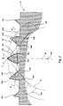
- Figure 2 depicts one particular cross-section of the circumferential portion of the tool 2, which cross-section is taken perpendicular to the screw direction of the ribs.
- the profile on the disc 12 has the shape of a number of adjacent profile teeth 21a-e.
- the profile shape is based on the base geometry of a pinion, characteristic for the crown wheel 1 to be manufactured, having involute toothing.
- Figure 2 indicates, as broken lines, the base circle 22 and the involute toothing 23a-e of the characteristic pinion.
- the centre M of the base circle 22 lies on a circle which lies in a plane W perpendicular to the rotational axis 11 of the tool (not shown in Figure 2) and whose centre lies on said rotational axis.
- each profile tooth 21b-d are formed, as in the known tool according to WO-A-92/09395, by a straight line perpendicular to a tangent l, l', or m, m' to the base circle 22 of the characteristic pinion and/or a part of an involute of said base circle 22, of which the location of the foot on the base circle coincides with the foot 24b-d; 25b-d of an involute of a tooth 23b-d of the characteristic pinion on the base circle 22.
- the profile extending over the circumference of the disc 12 has such a shape that a portion thereof lies outside the surface of revolution which is formed by rotation of the addendum circle 26 of the characteristic pinion about the rotational axis 11 of the tool.
- this manifests itself by parts of profile teeth (profile teeth 21b-d) or entire profile teeth (profile teeth 21a and 21e) lying outside the addendum circle 26 of the characteristic pinion, seen from the centre M.
- the machining elements When manufacturing a crown wheel, the machining elements whose cutting edges lie on the portion of the profile lying outside the addendum circle of the characteristic pinion perform a premachining operation. As a result, compared to the known tool, the depth of cut is considerably reduced for the same starting speed. If the depth of cut is kept constant, the starting speed can be increased. This leads to a considerable shortening of the processing time. An increase of the starting speed by a factor 4 is possible.
- the final shape of the crown wheel teeth is determined by that portion of the profile which, in cross-section, has the shape of an involute.
- the starting point in defining the profile tooth shape is the centre line h of the profile. Located on the centre line h there is the centre M of the base circle R b , on which the feet of the involutes for the teeth T 1 , T 2 and T 3 of the characteristic pinion, P 1 and R 1 , P 2 and R 2 and P 3 and R 3 , respectively lie. P 1 Q 1 , R 1 Q 1 , P 2 Q 2 and R 2 Q 2 and P 3 Q 3 and R 3 Q 3 are then the involutes of the teeth of the pinion characteristic for the crown wheel.
- the crown wheel is characterized by its minimum and maximum pressure angle, where the smallest pressure angle ⁇ minimum is located on the internal diameter of the crown wheel and the maximum pressure angle ⁇ maximum on the outer diameter thereof.
- the tangents l and m are determined whose radius vectors to the point of tangency on the base circle form angles of ⁇ maximum and ⁇ minimum , respectively, with the profile centre line h, the radius vectors lying on the other side of the profile centre line h than the tooth flank in question with respect to the centre of the tooth. This therefore means that the tangent with the radius vector to the left of the centre line h is important for defining the right-hand tooth flank and vice versa.
- the tooth flank facing away from the profile centre line h is constructed by determining the intersections B 1 , B 2 and B 3 of the involutes of said flank or the extension thereof with the tangent m, which involutes intersect the tangent m perpendicularly.
- That part of the involute which lies above the tangent m forms part of the cutting edge, while below the tangent m the cutting edge is formed by the tangent to the involute at the location of B 1 , B 2 , B 3 , respectively, the direction of the tangent being identical to the perpendicular to the tangent m.
- the tooth flank facing the profile centre line h is constructed by determining the intersections A 1 , A 2 and A 3 of the involute of the flank with the tangent l. In so doing it is found that, in the situation at tooth T1, the involute of the tooth of the characteristic pinion does not intersect the line l perpendicularly, because the foot R 1 is located beyond the radius vector from the centre M to the tangent l. In this case, the other branch of the involute from the same foot R 1 is used, which gives rise to the intersection A 1 '. This branch of the involute intersects the tangent l perpendicularly.
- the cutting edge is formed, in the region below the tangent l, by the involute and, in the region above the tangent l, by the tangent to the involute in the intersection of the involute with tangent l.
- the tooth tip may be rounded. It is found that, owing to the tool profile chosen, some undercutting occurs in the tooth root of the crown wheel teeth to be shaped. Said undercutting is negligibly small, however, if the rounding radius is made sufficiently large.
- the depth of the tooth spaces between the profile teeth can be limited, as is indicated here by the line V.
- the tooth flanks are formed, from the foot of the involute to the line V, by the line which makes an angle ⁇ minimum with the centre line h.
- the hobbing tool according to the invention can be embodied as a hobbing milling cutter in the form of a disc having cutting teeth which are disposed on the circumference and are evenly distributed over the circumference. The cutting edges of said cutting teeth then lie in the surface of the profile described hereinabove.
- the hobbing tool according to the invention may also be embodied as a hobbing grinding disc in the form of a disc having disposed on its circumference a series of continuous ribs which are situated next to one another and extend in a circumferential direction. Said ribs are provided at their surface with grinding material in such a way that the cutting edges of the grinding material lie in the surface of the profile described hereinabove.
Landscapes
- Engineering & Computer Science (AREA)
- Mechanical Engineering (AREA)
- Gear Processing (AREA)
- Milling Processes (AREA)
Abstract
Claims (6)
- Outil (2) pour fabriquer des couronnes dentées (1) dont l'angle de pression est compris entre une valeur minimale et une valeur maximale au moyen d'une opération d'usinage par taille en développante dans laquelle un outil (2) et une pièce (1) tournent avec un rapport constant entre leurs vitesses de rotation et se déplacent l'un par rapport à l'autre d'une manière telle que l'outil usine la pièce en continu, ledit outil étant constitué par un disque (12) qui peut tourner autour de son axe (11) et sur la circonférence duquel sont disposés des éléments d'usinage dont les arêtes de coupe sont situées dans la surface d'un profil qui s'étend sur la circonférence du disque sous la forme de nervures sensiblement hélicoïdales (13), cependant que le profil présente, dans chaque plan de section transversale perpendiculaire à la direction de l'hélice des nervures, la forme d'une pluralité de dents (21a à 21e) du profil situées les unes à côté des autres, que ladite forme du profil est basée sur la géométrie de base d'un pignon qui est caractéristique de la couronne dentée à fabriquer, qui présente une denture en développante (23a à 23e) et dont le centre (M) du cercle de base (22) est placé sur un cercle situé dans un plan (W) perpendiculaire à l'axe de rotation (11) de l'outil, son centre étant situé sur ledit axe de rotation, d'une manière telle que chacun des deux flancs de chaque dent (21b à 21d) du profil soit formé par une ligne droite perpendiculaire à une tangente (l, l' ; m, m') au cercle de base (22) du pignon caractéristique et/ou par une partie d'une développante dudit cercle de base dont la position du pied sur le cercle de base coincide avec le pied (24b à 24d ; 25b à 25d) d'une développante d'une dent (23b à 23d) du pignon caractéristique sur le cercle de base, caractérisé par le fait que le profil qui s'étend sur la circonférence du disque (12) présente une forme telle qu'une partie de celui-ci soit située à l'extérieur de la surface de révolution engendrée par la rotation du cercle de tête (26) du pignon caractéristique autour de l'axe de rotation (11) de l'outil, de sorte que l'outil présente des éléments d'usinage ou des parties d'éléments d'usinage dont les arêtes de coupe sont situées dans la surface de ladite partie du profil et peuvent servir à réaliser une opération d'usinage préalable lorsque l'on fabrique une couronne dentée.
- Outil selon la revendication 1, caractérisé par le fait que, dans chaque plan en coupe transversale perpendiculaire à la direction de l'hélice des nervures,le flanc de chaque dent du profil qui est dirigé vers l'axe central (h) du profil, qui passe par le centre (M) du cercle de base (Rb) du pignon caractéristique et qui est perpendiculaire à l'axe de rotation de l'outil, est formé,dans la région située entre le cercle de base (Rb) du pignon caractéristique et une première tangente (l) audit cercle de base dont le point de tangence est situé du même côté de l'axe central (h) que le flanc de dent en question et dont le rayon vecteur allant du centre du cercle de base au point de tangence fait avec l'axe central (h) un angle égal à l'angle de pression maximal de la couronne dentée à fabriquer, par une partie de la branche d'une développante du cercle de base qui coupe la première tangente (l) sous un angle droit, et :dans la région qui, vue depuis l'axe de rotation de l'outil, est située à l'extérieur de la première tangente (l), par la tangente à la branche de la développante qui coupe la première tangente (l) sous un angle droit, à l'endroit de l'intersection de ladite branche de la développante et de la première tangente (l), et :le flanc de chaque dent du profil qui est dirigé à l'opposé de l'axe central (h) du profit est formé,dans la région qui, vue depuis l'axe de rotation de l'outil, est située à l'extérieur d'une deuxième tangente (m) au cercle de base (Rb) dont le point de tangence est situé de l'autre côté de l'axe central (h) par rapport au flanc de dent en question et dont le rayon vecteur allant du centre du cercle de base au point de tangence fait avec l'axe central (h) un angle qui est égal à l'angle de pression minimal de la couronne dentée à fabriquer, par une partie de la branche d'une développante du cercle de base qui coupe la deuxième tangente (m) sous un angle droit, et :dans la région qui, vue depuis l'axe de rotation de l'outil, est située à l'intérieur de la deuxième tangente (m), par la tangente à la branche de la développante qui coupe la deuxième tangente (m) sous un angle droit, à l'endroit de l'intersection de ladite branche de la développante et de la deuxième tangente (m),les deux flancs de chaque dent du profil convergeant sur la circonférence extérieure de l'outil.
- Outil selon la revendication 2, caractérisé par le fait que les deux flancs de chaque dent du profil convergent selon un arrondi qui présente un rayon de courbure minimal prédéterminé.
- Outil selon la revendication 2 ou 3, caractérisé par le fait que le flanc de chaque dent du profil qui est dirigé vers l'axe central (h) du profil est formé, dans la région située à l'intérieur du cercle de base du pignon caractéristique, par une droite qui est reliée à la développante et qui forme avec l'axe central (h) un angle sensiblement égal à l'angle de pression minimal de la couronne dentée à fabriquer.
- Outil selon les revendications 1 à 4, caractérisé par le fait que l'outil est une fraise, et que les éléments d'usinage sont des lames de coupe.
- Outil selon les revendications 1 à 4, caractérisé par le fait que l'outil est une meule, et que les éléments d'usinage sont des particules abrasives.
Applications Claiming Priority (3)
| Application Number | Priority Date | Filing Date | Title |
|---|---|---|---|
| NL9300226 | 1993-02-04 | ||
| NL9300226A NL9300226A (nl) | 1993-02-04 | 1993-02-04 | Gereedschap voor het vervaardigen van kroonwielen. |
| PCT/NL1994/000028 WO1994017945A1 (fr) | 1993-02-04 | 1994-02-03 | Outil de fabrication de couronnes dentees |
Publications (2)
| Publication Number | Publication Date |
|---|---|
| EP0682586A1 EP0682586A1 (fr) | 1995-11-22 |
| EP0682586B1 true EP0682586B1 (fr) | 1997-05-07 |
Family
ID=19862027
Family Applications (1)
| Application Number | Title | Priority Date | Filing Date |
|---|---|---|---|
| EP94907015A Expired - Lifetime EP0682586B1 (fr) | 1993-02-04 | 1994-02-03 | Outil de fabrication de couronnes dentees |
Country Status (6)
| Country | Link |
|---|---|
| US (1) | US5622459A (fr) |
| EP (1) | EP0682586B1 (fr) |
| JP (1) | JP3637357B2 (fr) |
| DE (1) | DE69403064T2 (fr) |
| NL (1) | NL9300226A (fr) |
| WO (1) | WO1994017945A1 (fr) |
Families Citing this family (6)
| Publication number | Priority date | Publication date | Assignee | Title |
|---|---|---|---|---|
| NL9300826A (nl) * | 1993-05-13 | 1994-12-01 | Crown Gear Bv | Gereedschap voor het vervaardigen van een kroonwiel dat kan samenwerken met een rondsel met schuine tanden en werkwijze voor het vervaardigen van een dergelijk kroonwiel. |
| NL9402055A (nl) * | 1994-12-07 | 1996-07-01 | Crown Gear Bv | Afwikkelfrees voor het bewerken van kroonwielen, alsmede werkwijze voor het vervaardigen van een dergelijk gereedschap. |
| US5931612A (en) * | 1994-12-07 | 1999-08-03 | Crown Gear, B.V. | Hob cutter for machining face gears, and method for manufacturing such a tool |
| JP5748582B2 (ja) | 2011-07-12 | 2015-07-15 | 三菱重工業株式会社 | ねじ状工具の製作方法 |
| JP5832953B2 (ja) * | 2012-05-16 | 2015-12-16 | 株式会社小笠原プレシジョン・エンジニアリング | 歯車を切削するための工具、及び、歯車を切削する方法 |
| JP6312755B2 (ja) * | 2016-08-09 | 2018-04-18 | 本田技研工業株式会社 | プーリの被検出面の加工方法 |
Family Cites Families (4)
| Publication number | Priority date | Publication date | Assignee | Title |
|---|---|---|---|---|
| DE1527125A1 (de) * | 1964-03-19 | 1969-11-27 | Leimbach Kg Hermann | Waelzfraeser |
| DE2240951C2 (de) * | 1972-08-19 | 1974-10-03 | Hermann Leimbach Kg, 5600 Wuppertalbarmen | Wälzfräser |
| NL8902417A (nl) * | 1989-09-28 | 1991-04-16 | Crown Gear Bv | Gereedschap voor het vervaardigen van kroonwielen. |
| NL9002611A (nl) * | 1990-11-29 | 1992-06-16 | Crown Gear Bv | Gereedschap voor het vervaardigen van kroonwielen, alsmede werkwijze voor het vervaardigen van een dergelijk gereedschap. |
-
1993
- 1993-02-04 NL NL9300226A patent/NL9300226A/nl not_active Application Discontinuation
-
1994
- 1994-02-03 EP EP94907015A patent/EP0682586B1/fr not_active Expired - Lifetime
- 1994-02-03 JP JP51790394A patent/JP3637357B2/ja not_active Expired - Lifetime
- 1994-02-03 DE DE69403064T patent/DE69403064T2/de not_active Expired - Lifetime
- 1994-02-03 WO PCT/NL1994/000028 patent/WO1994017945A1/fr not_active Ceased
- 1994-02-03 US US08/464,840 patent/US5622459A/en not_active Expired - Lifetime
Also Published As
| Publication number | Publication date |
|---|---|
| WO1994017945A1 (fr) | 1994-08-18 |
| US5622459A (en) | 1997-04-22 |
| EP0682586A1 (fr) | 1995-11-22 |
| JP3637357B2 (ja) | 2005-04-13 |
| JPH08506768A (ja) | 1996-07-23 |
| DE69403064T2 (de) | 1997-08-21 |
| NL9300226A (nl) | 1994-09-01 |
| DE69403064D1 (de) | 1997-06-12 |
Similar Documents
| Publication | Publication Date | Title |
|---|---|---|
| US4850155A (en) | Method for machining gearwheels | |
| US4635404A (en) | Apparatus for machining a spur gear by means of a rotating gearlike tool | |
| KR100188457B1 (ko) | 나사식 연삭숫돌의 드레싱방법 | |
| KR102555094B1 (ko) | 치형부를 기계가공하는 방법, 툴 장치 및 치성형 머신 | |
| EP0559798B1 (fr) | Outil pour la production de couronnes dentees et procede de production dudit outil | |
| JP3665874B2 (ja) | 斜め歯を持つ小歯車と噛合し得る冠歯車を製造するための加工具及びそのような冠歯車を製造するための方法 | |
| CA2517724C (fr) | Procede, lame a barre et son utilisation pour fraiser des engrenages coniques a dentures helicoidales et des engrenages hypoides | |
| US5158400A (en) | Rotary disc cutter and method of making same | |
| EP0682586B1 (fr) | Outil de fabrication de couronnes dentees | |
| US5033239A (en) | Disposable hob and method of grinding the same | |
| EP0693016B1 (fr) | Procede de production d'une couronne dentee | |
| US4627770A (en) | Gear cutter | |
| JP2018051753A (ja) | 半仕上げ法においてフェースカップリングワークピースの歯面を機械加工する方法 | |
| CN119457275A (zh) | 用于齿部铣削的装置及方法 | |
| CN120091881A (zh) | 制造具有齿顶和/或齿根修形的齿轮 | |
| JPH0631533A (ja) | 歯車形の仕上げ加工用工具を創成する方法および歯車形の工具 | |
| EP0760728A1 (fr) | Procede de fabrication d'une fraise-mere | |
| US20260124690A1 (en) | Manufacturing gears with tip and/or root relief | |
| KR20250159153A (ko) | 호브 필링, 하드 필링 또는 기어 셰이핑에 의한 기어 가공, 및 대응하는 기어 절삭 공구 | |
| US3689966A (en) | Rotary cutter with helically directed cutting teeth arranged in a circle | |
| JPS6216768B2 (fr) | ||
| JPS6034218A (ja) | ピニオンカツタ |
Legal Events
| Date | Code | Title | Description |
|---|---|---|---|
| PUAI | Public reference made under article 153(3) epc to a published international application that has entered the european phase |
Free format text: ORIGINAL CODE: 0009012 |
|
| 17P | Request for examination filed |
Effective date: 19950731 |
|
| AK | Designated contracting states |
Kind code of ref document: A1 Designated state(s): DE FR GB IT NL |
|
| 17Q | First examination report despatched |
Effective date: 19951201 |
|
| GRAG | Despatch of communication of intention to grant |
Free format text: ORIGINAL CODE: EPIDOS AGRA |
|
| GRAH | Despatch of communication of intention to grant a patent |
Free format text: ORIGINAL CODE: EPIDOS IGRA |
|
| GRAH | Despatch of communication of intention to grant a patent |
Free format text: ORIGINAL CODE: EPIDOS IGRA |
|
| GRAA | (expected) grant |
Free format text: ORIGINAL CODE: 0009210 |
|
| ITF | It: translation for a ep patent filed | ||
| AK | Designated contracting states |
Kind code of ref document: B1 Designated state(s): DE FR GB IT NL |
|
| REF | Corresponds to: |
Ref document number: 69403064 Country of ref document: DE Date of ref document: 19970612 |
|
| ET | Fr: translation filed | ||
| PLBE | No opposition filed within time limit |
Free format text: ORIGINAL CODE: 0009261 |
|
| STAA | Information on the status of an ep patent application or granted ep patent |
Free format text: STATUS: NO OPPOSITION FILED WITHIN TIME LIMIT |
|
| 26N | No opposition filed | ||
| REG | Reference to a national code |
Ref country code: GB Ref legal event code: IF02 |
|
| NLS | Nl: assignments of ep-patents |
Owner name: CROWN GEAR HOLDING B.V. |
|
| NLS | Nl: assignments of ep-patents |
Owner name: NORMA B.V. |
|
| REG | Reference to a national code |
Ref country code: GB Ref legal event code: 732E |
|
| NLS | Nl: assignments of ep-patents |
Owner name: ASS AG |
|
| REG | Reference to a national code |
Ref country code: FR Ref legal event code: TP |
|
| REG | Reference to a national code |
Ref country code: GB Ref legal event code: 732E |
|
| REG | Reference to a national code |
Ref country code: FR Ref legal event code: TP |
|
| PGFP | Annual fee paid to national office [announced via postgrant information from national office to epo] |
Ref country code: FR Payment date: 20120320 Year of fee payment: 19 |
|
| PGFP | Annual fee paid to national office [announced via postgrant information from national office to epo] |
Ref country code: DE Payment date: 20120224 Year of fee payment: 19 |
|
| PGFP | Annual fee paid to national office [announced via postgrant information from national office to epo] |
Ref country code: IT Payment date: 20120224 Year of fee payment: 19 Ref country code: GB Payment date: 20120131 Year of fee payment: 19 |
|
| PGFP | Annual fee paid to national office [announced via postgrant information from national office to epo] |
Ref country code: NL Payment date: 20120301 Year of fee payment: 19 |
|
| REG | Reference to a national code |
Ref country code: NL Ref legal event code: V1 Effective date: 20130901 |
|
| GBPC | Gb: european patent ceased through non-payment of renewal fee |
Effective date: 20130203 |
|
| PG25 | Lapsed in a contracting state [announced via postgrant information from national office to epo] |
Ref country code: NL Free format text: LAPSE BECAUSE OF NON-PAYMENT OF DUE FEES Effective date: 20130901 |
|
| REG | Reference to a national code |
Ref country code: FR Ref legal event code: ST Effective date: 20131031 |
|
| REG | Reference to a national code |
Ref country code: DE Ref legal event code: R119 Ref document number: 69403064 Country of ref document: DE Effective date: 20130903 |
|
| PG25 | Lapsed in a contracting state [announced via postgrant information from national office to epo] |
Ref country code: IT Free format text: LAPSE BECAUSE OF NON-PAYMENT OF DUE FEES Effective date: 20130203 |
|
| PG25 | Lapsed in a contracting state [announced via postgrant information from national office to epo] |
Ref country code: DE Free format text: LAPSE BECAUSE OF NON-PAYMENT OF DUE FEES Effective date: 20130903 Ref country code: FR Free format text: LAPSE BECAUSE OF NON-PAYMENT OF DUE FEES Effective date: 20130228 Ref country code: GB Free format text: LAPSE BECAUSE OF NON-PAYMENT OF DUE FEES Effective date: 20130203 |