EP0682908B1 - Filtereinrichtung für einen Staubsauger - Google Patents
Filtereinrichtung für einen Staubsauger Download PDFInfo
- Publication number
- EP0682908B1 EP0682908B1 EP95107242A EP95107242A EP0682908B1 EP 0682908 B1 EP0682908 B1 EP 0682908B1 EP 95107242 A EP95107242 A EP 95107242A EP 95107242 A EP95107242 A EP 95107242A EP 0682908 B1 EP0682908 B1 EP 0682908B1
- Authority
- EP
- European Patent Office
- Prior art keywords
- closure plate
- holding plate
- filter device
- plate
- opening
- Prior art date
- Legal status (The legal status is an assumption and is not a legal conclusion. Google has not performed a legal analysis and makes no representation as to the accuracy of the status listed.)
- Expired - Lifetime
Links
- 239000000428 dust Substances 0.000 title 1
- 238000006073 displacement reaction Methods 0.000 claims description 2
- 230000003313 weakening effect Effects 0.000 claims 2
- 230000006978 adaptation Effects 0.000 description 1
- 239000000463 material Substances 0.000 description 1
- 239000000123 paper Substances 0.000 description 1
Images
Classifications
-
- A—HUMAN NECESSITIES
- A47—FURNITURE; DOMESTIC ARTICLES OR APPLIANCES; COFFEE MILLS; SPICE MILLS; SUCTION CLEANERS IN GENERAL
- A47L—DOMESTIC WASHING OR CLEANING; SUCTION CLEANERS IN GENERAL
- A47L9/00—Details or accessories of suction cleaners, e.g. mechanical means for controlling the suction or for effecting pulsating action; Storing devices specially adapted to suction cleaners or parts thereof; Carrying-vehicles specially adapted for suction cleaners
- A47L9/10—Filters; Dust separators; Dust removal; Automatic exchange of filters
- A47L9/14—Bags or the like; Rigid filtering receptacles; Attachment of, or closures for, bags or receptacles
- A47L9/1427—Means for mounting or attaching bags or filtering receptacles in suction cleaners; Adapters
- A47L9/1436—Connecting plates, e.g. collars, end closures
- A47L9/1445—Connecting plates, e.g. collars, end closures with closure means
Definitions
- the invention relates to a filter device for a vacuum cleaner with a filter bag and a dimensionally stable one attached to it and provided with an inflow opening Holding plate and with a displaceable in its longitudinal direction, with a Breakthrough provided closure plate, which in a the inflow opening of the Holding plate releasing and covering position can be brought and an opposite the holding plate, protruding, strip-shaped handle, and damage-free can be formed into an arch or a roll.
- the closure plate is in one Positioned that the opening of the closure plate with the inflow opening the holding plate matches when the filter device is in a vacuum cleaner is inserted.
- the closure plate is opened moved relative to the holding plate, so that the inflow opening is closed.
- the free edge of the locking plate is available assigned area opposite the assigned transverse edge of the holding plate, see above that this area of the closure plate is a handle.
- the flexible, paper closure plate at the top and bottom a dimensionally stable strip made of cardboard.
- the top bar is opposite the holding plate in front, so that to close the flow opening gripped it can be.
- the bottom bar forms a stop, since it closes after closing the flow opening strikes against the holding plate. Should the flow opening can be opened again after closing, the closing plate can be moved by pulling on the bottom bar.
- the lid only opens at an angle of approx. 45 °. Especially at these vacuum cleaners the protruding handle in the course of closing the Lid deformed. This leads to damage to the closure plate, since the protruding Handle is rigid.
- the present invention has for its object a filter device Type described above so that the associated with the free edge Area that can also be used as a handle, the contour of the Vacuum cleaner or the vacuum cleaner cover can adjust itself.
- the object is achieved by at least the area of the closure plate between the opening and the free edge that can be used as a handle has slats produced by incisions running in the direction of displacement, so that it can be formed into a sheet or a roll without damage.
- the deformable area is from the same material as the rest of the area.
- the thicknesses also match. There this area can be formed into an arch or a roll, one takes place automatically Adaptation to the inner contour of the vacuum cleaner or the vacuum cleaner cover.
- the Slats can be produced in the simplest way. They offer the advantage that the area rolls like a blind.
- the individual slats are analogous a film hinge joined together because the depth of the incisions is a little bit is less than the thickness of the closure plate.
- the slats also have the advantage that the closure plate does not buckle when the inflow of the Holding plate covering position in the position exposing the inflow opening is pushed back. If necessary, the inflow opening can accordingly open and close several times
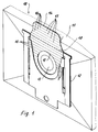
- the filter device shown in Figures 1 and 2 includes a filter bag that works as a block or block bottom bag 11 is formed. On the outside of the bottom of the Block bottom bag 11 is made of cardboard Holding plate 12 glued.
- the holding plate 12 is with a Inflow opening 13 provided.
- the holding plate 12 is with Provided guides for a slidable closure plate 14.
- the closure plate 14 has a circular opening 15 whose diameter is larger than that of the inflow opening 13 of the holding plate 12.
- the longitudinal edges of the closing plate 14 jump inward in the area of the free edge around this Mark the area as a handle. This area stands opposite the assigned transverse edge of the holding plate 12, when the inflow opening 13 of the holding plate 12 is released is.
- the range is from Center of the opening 15 to the outer free edge formed from individual slats 16, which are transverse to the Longitudinal incisions 17 are formed.
- the Incisions 17 lie on the block or block bottom bag 11 opposite side, so that the area of the slats 16 curved towards the block or block bottom bag 11 and with a corresponding length also form into a roll can.
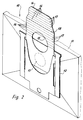
- this is Vacuum cleaner housing or the lid not shown. It it follows from the drawings that the closure plate 14 not only in that shown in Figure 2 Lock position can be pulled, but also counter this direction can be pushed back without danger the kink or deflection exists.
- the closure plate 14 consist of individual slats over the entire length.
- the closure plate 14 with a line of weakness running transverse to the longitudinal edges 18 in the form of a perforation, which is at a distance from free edge of the closure plate 14 lies.
- This line of weakness 18 is placed so that it with the associated transverse edge the holding plate 12 coincides when the inflow opening 13 is released. Through this line of weakness 18 the deformation of the protruding part is still favored.
Landscapes
- Engineering & Computer Science (AREA)
- Mechanical Engineering (AREA)
- Filters For Electric Vacuum Cleaners (AREA)
- Packages (AREA)
Description
- Figur 1
- die erfindungsgemäße Filtereinrichtung in einer Teilansicht, bei der die Einströmöffnung freigegeben ist,
- Figur 2
- eine der Figur 1 entsprechende Darstellung jedoch mit geschlossener Einströmöffnung.
Claims (4)
- Filtereinrichtung für einen Staubsauger mit einem Filterbeutel (11) und einer daran befestigten, mit einer Einströmöffnung (13) versehenen formstabilen Halteplatte (12) und mit einer in ihrer Längsrichtung verschiebbaren, mit einer Durchbrechung (15) versehenen Verschlußplatte (14), die in eine die Einströmöffnung (13) der Halteplatte (12) freigebende oder abdeckende Stellung bringbar ist und eine gegenüber der Halteplatte (12) vorstehende, streifenförmige Handhabe aufweist und beschädigungsfrei zu einem Bogen oder einer Rolle formbar ist, dadurch gekennzeichnet, daß zumindest der Bereich der Verschlußplatte (14) zwischen der Durchbrechung (15) und dem als Handhabe benutzbaren freien Rand quer zur Verschieberichtung verlaufende, durch Einschnitte (17) hergestellte Lamellen (16) aufweist.
- Filtereinrichtung nach Anspruch 1, dadurch gekennzeichnet, daß der von der Mitte der Durchbrechung (15) der Verschlußplatte (14) bis zur äußeren freien Kante sich erstreckende Bereich durch die Lamellen (16) gebildet ist.
- Filtereinrichtung nach Anspruch 1, dadurch gekennzeichnet, daß die Verschlußplatte (14) mit einer quer zu den Längskanten und im Abstand zur freien Kante verlaufenden Schwächungslinie (18), vorzugsweise in Form einer Perforation, versehen ist.
- Filtereinrichtung nach Anspruch 3, dadurch gekennzeichnet, daß die Schwächungslinie (18) mit der zugeordneten Querkante der Halteplatte (12) in der die Einströmöffnung (13) freigebenden Stellung zusammenfällt.
Applications Claiming Priority (2)
| Application Number | Priority Date | Filing Date | Title |
|---|---|---|---|
| DE9408349U | 1994-05-20 | ||
| DE9408349U DE9408349U1 (de) | 1994-05-20 | 1994-05-20 | Filtereinrichtung für einen Staubsauger |
Publications (2)
| Publication Number | Publication Date |
|---|---|
| EP0682908A1 EP0682908A1 (de) | 1995-11-22 |
| EP0682908B1 true EP0682908B1 (de) | 1998-11-25 |
Family
ID=6908917
Family Applications (1)
| Application Number | Title | Priority Date | Filing Date |
|---|---|---|---|
| EP95107242A Expired - Lifetime EP0682908B1 (de) | 1994-05-20 | 1995-05-12 | Filtereinrichtung für einen Staubsauger |
Country Status (2)
| Country | Link |
|---|---|
| EP (1) | EP0682908B1 (de) |
| DE (2) | DE9408349U1 (de) |
Cited By (2)
| Publication number | Priority date | Publication date | Assignee | Title |
|---|---|---|---|---|
| WO2017194081A1 (en) | 2016-05-09 | 2017-11-16 | Aktiebolaget Electrolux | Dust container for a vacuum cleaner |
| CN108078493A (zh) * | 2016-11-23 | 2018-05-29 | 伊莱克斯公司 | 真空吸尘器灰尘容器的装置 |
Families Citing this family (12)
| Publication number | Priority date | Publication date | Assignee | Title |
|---|---|---|---|---|
| DE29821528U1 (de) | 1998-12-02 | 1999-02-11 | Neu Kaliß Spezialpapier GmbH, 19294 Neu Kaliß | Filterbeutel |
| DE10203405B4 (de) * | 2001-01-27 | 2013-06-20 | Wolf Pvg Gmbh & Co. Kg | Filtervorrichtung für einen Staubsauger |
| DE20101471U1 (de) | 2001-01-27 | 2001-04-19 | Wolf GmbH, 32602 Vlotho | Filtervorrichtung für einen Staubsauger |
| GB2374524B (en) * | 2001-04-17 | 2004-08-04 | Hoover Ltd | Vacuum cleaner |
| DE20200551U1 (de) * | 2002-01-09 | 2002-04-04 | Branofilter Gmbh | Anschlussstück eines Staubfilterbeutels |
| DE202006016789U1 (de) | 2006-11-03 | 2006-12-28 | Branofilter Gmbh | Anschlussstück für einen Staubfilterbeutel sowie mit einem solchen Anschlussstück ausgestatteter Staubfilterbeutel |
| CN109068912B (zh) * | 2016-05-09 | 2022-03-18 | 伊莱克斯公司 | 用于生产灰尘容器的方法及灰尘容器的连接板 |
| AU2016406757B2 (en) * | 2016-05-09 | 2023-01-19 | Aktiebolaget Electrolux | Connector plate for a vacuum cleaner dust container and a dust container |
| JP1740369S (ja) * | 2022-01-29 | 2023-03-29 | 掃除機用集塵袋固定具 | |
| USD989429S1 (en) * | 2023-02-21 | 2023-06-13 | Dongguan Huaying Zhizao Co., Ltd. | Dust bag |
| CN119097240A (zh) * | 2023-06-09 | 2024-12-10 | 江苏美的清洁电器股份有限公司 | 尘杯、吸尘器和集尘系统 |
| USD1108053S1 (en) * | 2024-06-21 | 2025-12-30 | Dongguan Huaying Zhizao Co., Ltd. | Dust bag |
Family Cites Families (5)
| Publication number | Priority date | Publication date | Assignee | Title |
|---|---|---|---|---|
| EP0409038B1 (de) * | 1989-07-21 | 1994-03-16 | Siemens Aktiengesellschaft | Staubsaugerfilterbeutel mit einer steifen Halteplatte |
| DE9101699U1 (de) * | 1991-02-14 | 1991-08-01 | Wolfgang B. Schroeter GmbH, 4973 Vlotho | Filtereinrichtung für einen Staubsauger |
| DE9201802U1 (de) * | 1992-02-13 | 1992-04-02 | Wolfgang B. Schroeter GmbH, 4973 Vlotho | Filtereinrichtung für einen Staubsauger |
| DE9302001U1 (de) * | 1993-02-12 | 1993-04-15 | Wolfgang B. Schroeter GmbH, 4973 Vlotho | Filtereinrichtung für einen Staubsauger |
| DE9403970U1 (de) * | 1994-03-09 | 1994-05-05 | Aichner, Paul, 92345 Dietfurt | Halteplatte eines Staubsauger-Filterbeutels |
-
1994
- 1994-05-20 DE DE9408349U patent/DE9408349U1/de not_active Expired - Lifetime
-
1995
- 1995-05-12 EP EP95107242A patent/EP0682908B1/de not_active Expired - Lifetime
- 1995-05-12 DE DE59504304T patent/DE59504304D1/de not_active Expired - Lifetime
Cited By (2)
| Publication number | Priority date | Publication date | Assignee | Title |
|---|---|---|---|---|
| WO2017194081A1 (en) | 2016-05-09 | 2017-11-16 | Aktiebolaget Electrolux | Dust container for a vacuum cleaner |
| CN108078493A (zh) * | 2016-11-23 | 2018-05-29 | 伊莱克斯公司 | 真空吸尘器灰尘容器的装置 |
Also Published As
| Publication number | Publication date |
|---|---|
| EP0682908A1 (de) | 1995-11-22 |
| DE59504304D1 (de) | 1999-01-07 |
| DE9408349U1 (de) | 1994-07-21 |
Similar Documents
| Publication | Publication Date | Title |
|---|---|---|
| EP0682908B1 (de) | Filtereinrichtung für einen Staubsauger | |
| EP0132250B1 (de) | Folienkleinverpackung für Papier- bzw. Zellstofftaschentücher | |
| DE60301806T2 (de) | Schachtel mit Verschlusswandelement, Sicherheitssiegel und Elementen zum Wiederverschließen des Wandelements und Zuschnitt dafür | |
| CH627140A5 (en) | Box for packing oblong objects | |
| DE9014065U1 (de) | Verpackung aus (Kunststoff-) Folie | |
| DE3034363C2 (de) | Verkaufspackung | |
| DE3340798C2 (de) | Verpackung mit einem Garantieverschluß in Form einer Schachtel aus Karton | |
| EP0828662A1 (de) | Wiederverschliessbare faltschachtel mit öffnungssicherung | |
| EP0108990A2 (de) | Faltschachtel | |
| EP0627189B1 (de) | Filterbeutel, insbesondere für Staubsauger | |
| DE2615050A1 (de) | Pappkarton | |
| DE4121914A1 (de) | Weichpackung aus kunststoffolie zur aufnahme eines stapels von gefalteten erzeugnissen aus papier, tissue ect., insbesondere von papiertaschentuechern und servietten | |
| DE9316489U1 (de) | Kappenschachtel | |
| DE9016893U1 (de) | Staubsaugereinsatzbeutel | |
| DE1063526B (de) | Behaelter fuer Zigaretten od. dgl. | |
| DE9302002U1 (de) | Filtereinrichtung für einen Staubsauger | |
| EP0098314A1 (de) | Faltschachtel mit einer aufreissbaren Ausgussöffnung | |
| DE29819699U1 (de) | Halteplatte eines Staubsauger-Filterbeutels | |
| DE9405637U1 (de) | Filter-Einsatz-Beutel, insbesondere für Staubsauger | |
| DE8706581U1 (de) | Faltschachtel | |
| EP0823380B1 (de) | Wiederverschliessbare Faltschachtel mit aufreissbarer Oeffnungslasche | |
| DE19925070C2 (de) | Verschlußstück für Staubsauger-Filterbeutel und Verfahren zu seiner Herstellung | |
| DE9006537U1 (de) | Weichpackung aus Kunststoffolie zur Aufnahme eines Stapels von Papiertaschentüchern | |
| DE1761738B1 (de) | Aus einem Zuschnitt gefertigte Schachtel fuer Zigaretten oder Zigarillos | |
| DE1265036B (de) | Fuellventil fuer Beutel |
Legal Events
| Date | Code | Title | Description |
|---|---|---|---|
| PUAI | Public reference made under article 153(3) epc to a published international application that has entered the european phase |
Free format text: ORIGINAL CODE: 0009012 |
|
| AK | Designated contracting states |
Kind code of ref document: A1 Designated state(s): BE DE FR NL SE |
|
| 17P | Request for examination filed |
Effective date: 19960227 |
|
| 17Q | First examination report despatched |
Effective date: 19970408 |
|
| GRAG | Despatch of communication of intention to grant |
Free format text: ORIGINAL CODE: EPIDOS AGRA |
|
| GRAG | Despatch of communication of intention to grant |
Free format text: ORIGINAL CODE: EPIDOS AGRA |
|
| GRAH | Despatch of communication of intention to grant a patent |
Free format text: ORIGINAL CODE: EPIDOS IGRA |
|
| GRAH | Despatch of communication of intention to grant a patent |
Free format text: ORIGINAL CODE: EPIDOS IGRA |
|
| RBV | Designated contracting states (corrected) |
Designated state(s): BE DE FR NL SE |
|
| GRAA | (expected) grant |
Free format text: ORIGINAL CODE: 0009210 |
|
| AK | Designated contracting states |
Kind code of ref document: B1 Designated state(s): BE DE FR NL SE |
|
| REF | Corresponds to: |
Ref document number: 59504304 Country of ref document: DE Date of ref document: 19990107 |
|
| ET | Fr: translation filed | ||
| PLBE | No opposition filed within time limit |
Free format text: ORIGINAL CODE: 0009261 |
|
| STAA | Information on the status of an ep patent application or granted ep patent |
Free format text: STATUS: NO OPPOSITION FILED WITHIN TIME LIMIT |
|
| 26N | No opposition filed | ||
| PGFP | Annual fee paid to national office [announced via postgrant information from national office to epo] |
Ref country code: NL Payment date: 20030506 Year of fee payment: 9 |
|
| PG25 | Lapsed in a contracting state [announced via postgrant information from national office to epo] |
Ref country code: NL Free format text: LAPSE BECAUSE OF NON-PAYMENT OF DUE FEES Effective date: 20041201 |
|
| NLV4 | Nl: lapsed or anulled due to non-payment of the annual fee |
Effective date: 20041201 |
|
| PGFP | Annual fee paid to national office [announced via postgrant information from national office to epo] |
Ref country code: SE Payment date: 20090514 Year of fee payment: 15 |
|
| PGFP | Annual fee paid to national office [announced via postgrant information from national office to epo] |
Ref country code: FR Payment date: 20100611 Year of fee payment: 16 |
|
| PGFP | Annual fee paid to national office [announced via postgrant information from national office to epo] |
Ref country code: BE Payment date: 20100517 Year of fee payment: 16 |
|
| EUG | Se: european patent has lapsed | ||
| PG25 | Lapsed in a contracting state [announced via postgrant information from national office to epo] |
Ref country code: SE Free format text: LAPSE BECAUSE OF NON-PAYMENT OF DUE FEES Effective date: 20100513 |
|
| BERE | Be: lapsed |
Owner name: *WOLF G.M.B.H. Effective date: 20110531 |
|
| REG | Reference to a national code |
Ref country code: FR Ref legal event code: ST Effective date: 20120131 |
|
| PG25 | Lapsed in a contracting state [announced via postgrant information from national office to epo] |
Ref country code: BE Free format text: LAPSE BECAUSE OF NON-PAYMENT OF DUE FEES Effective date: 20110531 |
|
| PG25 | Lapsed in a contracting state [announced via postgrant information from national office to epo] |
Ref country code: FR Free format text: LAPSE BECAUSE OF NON-PAYMENT OF DUE FEES Effective date: 20110531 |
|
| REG | Reference to a national code |
Ref country code: DE Ref legal event code: R119 Ref document number: 59504304 Country of ref document: DE Effective date: 20121201 |
|
| PG25 | Lapsed in a contracting state [announced via postgrant information from national office to epo] |
Ref country code: DE Free format text: LAPSE BECAUSE OF NON-PAYMENT OF DUE FEES Effective date: 20121201 |
|
| PGFP | Annual fee paid to national office [announced via postgrant information from national office to epo] |
Ref country code: DE Payment date: 20110208 Year of fee payment: 17 |