EP0682910A1 - Instrument zur perkutanen Behandlung von Gewebeteilen - Google Patents
Instrument zur perkutanen Behandlung von Gewebeteilen Download PDFInfo
- Publication number
- EP0682910A1 EP0682910A1 EP95103395A EP95103395A EP0682910A1 EP 0682910 A1 EP0682910 A1 EP 0682910A1 EP 95103395 A EP95103395 A EP 95103395A EP 95103395 A EP95103395 A EP 95103395A EP 0682910 A1 EP0682910 A1 EP 0682910A1
- Authority
- EP
- European Patent Office
- Prior art keywords
- instrument
- instruments
- guide
- tube
- instrument according
- Prior art date
- Legal status (The legal status is an assumption and is not a legal conclusion. Google has not performed a legal analysis and makes no representation as to the accuracy of the status listed.)
- Withdrawn
Links
- 238000011282 treatment Methods 0.000 title claims abstract description 30
- 239000000523 sample Substances 0.000 claims abstract description 31
- 239000007788 liquid Substances 0.000 claims description 4
- 238000006073 displacement reaction Methods 0.000 claims 1
- 210000001519 tissue Anatomy 0.000 description 9
- 238000000034 method Methods 0.000 description 6
- 208000003618 Intervertebral Disc Displacement Diseases 0.000 description 3
- 210000003205 muscle Anatomy 0.000 description 3
- 230000005855 radiation Effects 0.000 description 3
- 206010050296 Intervertebral disc protrusion Diseases 0.000 description 2
- 239000003599 detergent Substances 0.000 description 2
- 239000012530 fluid Substances 0.000 description 2
- 238000011010 flushing procedure Methods 0.000 description 2
- 238000003780 insertion Methods 0.000 description 2
- 230000037431 insertion Effects 0.000 description 2
- 230000002262 irrigation Effects 0.000 description 2
- 238000003973 irrigation Methods 0.000 description 2
- 230000007246 mechanism Effects 0.000 description 2
- 125000006850 spacer group Chemical group 0.000 description 2
- 239000003795 chemical substances by application Substances 0.000 description 1
- 238000007796 conventional method Methods 0.000 description 1
- 238000005516 engineering process Methods 0.000 description 1
- 238000000605 extraction Methods 0.000 description 1
- 239000000835 fiber Substances 0.000 description 1
- 238000004519 manufacturing process Methods 0.000 description 1
- 230000003287 optical effect Effects 0.000 description 1
- 230000035515 penetration Effects 0.000 description 1
- 238000002360 preparation method Methods 0.000 description 1
- 238000007789 sealing Methods 0.000 description 1
- 238000004904 shortening Methods 0.000 description 1
Images



Classifications
-
- A—HUMAN NECESSITIES
- A61—MEDICAL OR VETERINARY SCIENCE; HYGIENE
- A61B—DIAGNOSIS; SURGERY; IDENTIFICATION
- A61B1/00—Instruments for performing medical examinations of the interior of cavities or tubes of the body by visual or photographical inspection, e.g. endoscopes; Illuminating arrangements therefor
- A61B1/00147—Holding or positioning arrangements
-
- A—HUMAN NECESSITIES
- A61—MEDICAL OR VETERINARY SCIENCE; HYGIENE
- A61B—DIAGNOSIS; SURGERY; IDENTIFICATION
- A61B1/00—Instruments for performing medical examinations of the interior of cavities or tubes of the body by visual or photographical inspection, e.g. endoscopes; Illuminating arrangements therefor
- A61B1/005—Flexible endoscopes
- A61B1/0051—Flexible endoscopes with controlled bending of insertion part
-
- A—HUMAN NECESSITIES
- A61—MEDICAL OR VETERINARY SCIENCE; HYGIENE
- A61B—DIAGNOSIS; SURGERY; IDENTIFICATION
- A61B1/00—Instruments for performing medical examinations of the interior of cavities or tubes of the body by visual or photographical inspection, e.g. endoscopes; Illuminating arrangements therefor
- A61B1/005—Flexible endoscopes
- A61B1/0051—Flexible endoscopes with controlled bending of insertion part
- A61B1/0052—Constructional details of control elements, e.g. handles
-
- A—HUMAN NECESSITIES
- A61—MEDICAL OR VETERINARY SCIENCE; HYGIENE
- A61B—DIAGNOSIS; SURGERY; IDENTIFICATION
- A61B1/00—Instruments for performing medical examinations of the interior of cavities or tubes of the body by visual or photographical inspection, e.g. endoscopes; Illuminating arrangements therefor
- A61B1/313—Instruments for performing medical examinations of the interior of cavities or tubes of the body by visual or photographical inspection, e.g. endoscopes; Illuminating arrangements therefor for introducing through surgical openings, e.g. laparoscopes
- A61B1/3135—Instruments for performing medical examinations of the interior of cavities or tubes of the body by visual or photographical inspection, e.g. endoscopes; Illuminating arrangements therefor for introducing through surgical openings, e.g. laparoscopes for examination of the epidural or the spinal space
-
- A—HUMAN NECESSITIES
- A61—MEDICAL OR VETERINARY SCIENCE; HYGIENE
- A61B—DIAGNOSIS; SURGERY; IDENTIFICATION
- A61B18/00—Surgical instruments, devices or methods for transferring non-mechanical forms of energy to or from the body
- A61B18/18—Surgical instruments, devices or methods for transferring non-mechanical forms of energy to or from the body by applying electromagnetic radiation, e.g. microwaves
- A61B18/20—Surgical instruments, devices or methods for transferring non-mechanical forms of energy to or from the body by applying electromagnetic radiation, e.g. microwaves using laser
- A61B18/22—Surgical instruments, devices or methods for transferring non-mechanical forms of energy to or from the body by applying electromagnetic radiation, e.g. microwaves using laser the beam being directed along or through a flexible conduit, e.g. an optical fibre; Couplings or hand-pieces therefor
- A61B18/24—Surgical instruments, devices or methods for transferring non-mechanical forms of energy to or from the body by applying electromagnetic radiation, e.g. microwaves using laser the beam being directed along or through a flexible conduit, e.g. an optical fibre; Couplings or hand-pieces therefor with a catheter
-
- A—HUMAN NECESSITIES
- A61—MEDICAL OR VETERINARY SCIENCE; HYGIENE
- A61B—DIAGNOSIS; SURGERY; IDENTIFICATION
- A61B17/00—Surgical instruments, devices or methods
- A61B17/00234—Surgical instruments, devices or methods for minimally invasive surgery
- A61B2017/00238—Type of minimally invasive operation
- A61B2017/00261—Discectomy
-
- A—HUMAN NECESSITIES
- A61—MEDICAL OR VETERINARY SCIENCE; HYGIENE
- A61B—DIAGNOSIS; SURGERY; IDENTIFICATION
- A61B17/00—Surgical instruments, devices or methods
- A61B2017/0046—Surgical instruments, devices or methods with a releasable handle; with handle and operating part separable
- A61B2017/00469—Surgical instruments, devices or methods with a releasable handle; with handle and operating part separable for insertion of instruments, e.g. guide wire, optical fibre
-
- A—HUMAN NECESSITIES
- A61—MEDICAL OR VETERINARY SCIENCE; HYGIENE
- A61B—DIAGNOSIS; SURGERY; IDENTIFICATION
- A61B17/00—Surgical instruments, devices or methods
- A61B17/34—Trocars; Puncturing needles
- A61B17/3417—Details of tips or shafts, e.g. grooves, expandable, bendable; Multiple coaxial sliding cannulas, e.g. for dilating
- A61B17/3421—Cannulas
- A61B2017/3445—Cannulas used as instrument channel for multiple instruments
Definitions
- the invention relates to an instrument for the percutaneous treatment of tissue parts with a guide instrument for instruments.
- the invention has for its object to remedy this situation, in particular to develop a guide instrument with which the tissue can be treated with precision and if necessary on a small scale.
- actuating means provided on the guiding instrument, with which the instruments can be guided precisely to the treatment site, treatment is possible in a significantly improved form, both qualitatively and in terms of time, by simplified and precisely adjustable handling.
- These actuating means are designed for finely adjustable movements and are attached to the outer end of the guiding instrument, where they can be manipulated by the surgeon, e.g. Turning, pushing rotary knobs, levers into a fine rotary or longitudinal movement of the instruments protruding at the proximal end. The degree of movement of the instruments can be read off scales.
- the instruments brought into the engaged position are locked by means of fixing buttons.
- the guide instrument is equipped with a fixation tube, which is fixed to an operating table with a fixation device after insertion into the tissue.
- the fixation tube thus serves as a guide and movement reference for the other instruments.
- the fixing tube can form the outermost guide tube or can be designed to be able to be guided within another external guide tube by means of a positioning device.
- a guide tube with a bendable tube end piece is provided, which are angled with actuating means can.
- Bendable pipes are already known. An embodiment is described for example in DE 42 22 121.
- the bendable guide tube preferably equipped with a positioning device, is guided inside the fixation tube, whereby it itself serves for the guidance and exact placement of further instruments in an environment outside the instrument axis line.
- the proximal ends of instruments such as laser probes, endoscopes, pliers, which protrude from the bendable end piece of the guide tube can be moved precisely in three dimensions in this way and can thus be guided precisely to the area to be treated, even if this area is not in the extension of the guide instrument lies.
- the invention also has the advantage that the dosage of laser energy can be greatly reduced compared to conventional methods due to the shortening of the distance between the probe and the tissue to be treated.
- the instruments guided in the guide tube are preferably also equipped with positioning devices.
- the guide instrument is equipped, in particular for percutaneous nucleotomy, both with an angled tube end piece and with mechanisms which can be actuated by hand, with which the instruments located in the guide tube can be advanced and rotated during a treatment.
- the guiding instrument is assigned a nucleoscope with a connector for suction and irrigation devices, so that the various treatment processes, including rinsing and suctioning, can be carried out in rapid succession.
- a fixing tube can be used as the nucleoscope, which, with an appropriate design, surrounds the guide tube while maintaining an annular gap to form a fluid channel.
- a flushing circuit through the guide instrument is preferably used for the transport of liquids. This not only enables the treatment site to be flushed or aspirated quickly, but also with high quality.
- the rinsing circuit can be easily carried out through a channel within an internal instrument set, e.g. Endoscope, and realize an annular channel, which is e.g. between the fixation tube or an internal instrument, such as the bendable guide tube.
- an endoscope or microendoscope with an integrated laser probe is provided, the laser probe being movable separately from the endoscope.
- Such an embodiment can also be equipped for large-scale irradiation. This can be achieved by a laser probe with a vertical or inclined radiation exit surface, which is arranged eccentrically in the endoscope. The radiation exit surface describes by rotating the laser probe or the endoscope circles of different sizes, with which radiation fields of different sizes can be produced.
- FIG. 1 shows an overall device for a monoportal percutaneous treatment, consisting essentially of a guide instrument 10 and a device connector 10 '.
- the guide instrument 10 has an outer fixing tube 11 and a bendable guide tube 12 contained therein, the proximal end piece 13 of which can be bended by approximately 90 ° by means of an actuating device and can be rotated and fixed around the longitudinal axis within the fixing tube 11 by means of a rotating device 15.
- the instruments that are required for the respective treatment are guided to the treatment site 16.
- the device connection 10 ' is formed as required and with the devices necessary for the respective intervention, e.g. Optical devices, mechanical devices for operating instruments, such as drills, rasps etc., connected.
- the guiding instrument 10 is also assigned actuating means for precise positioning of the instruments guided through the guiding tube 12.
- the guide tube 12 is fed directly manually or by means of a manually operated mechanical feed device, such as that identified by the reference number 19 and shown enlarged in FIG. 5.
- FIG. 2a shows a longitudinal section of the feed device 19 transverse to the toothed rollers 34.
- FIG. 2b is a longitudinal section perpendicular to FIG. 2a.
- one or more positioning devices for various instruments and / or guide tubes are assigned to the guide instrument 10, which can be coupled to one another by means of bayonet, screw or other closures in accordance with the respective application and form part of the guide instrument 10.
- the instruments can be rotated, advanced or withdrawn either in groups together or separately within a guide tube 12.
- a separate positioning device 22 is provided for the laser probe 17, with which the laser probe 17 can be rotated about its longitudinal axis separately from the microendoscope 18 and advanced in the longitudinal direction. It is of course also possible to connect the laser probe 17 to the microendoscope 18 so that both instruments can only be moved together.
- the instruments With the positioning devices 14, 15, 19, 22, 54, which can be operated manually by means of levers 23, rotary knobs 61, 66 or rotating rings 24, 38, 55, 62, 65, the instruments can be operated sensitively and consequently precisely (under X-ray observation) to the intended treatment site 16 are performed. With fixation buttons 25 to 29, 53, the instruments are finally fixed in the inserted positions if necessary.
- the guiding instrument 10 which can be assembled as required, is particularly well suited for micro-invasive percutaneous treatments due to the fine-graded and precise guideability even outside the instrument axis line.
- the proximal instrument ends can also be moved over larger areas at the treatment location by combining rotary movements and eccentric arrangements. An example of this is explained below with reference to FIGS. 3 and 4.
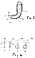
- FIG. 3 shows the proximal end 32 (see FIG. 1) of the guide instrument 10 in an enlarged representation.
- the microendoscope 18 is guided, which at the same time carries the laser probe 17 with an eccentric arrangement, which in the embodiment shown has an oblique beam exit surface 40. Due to the eccentricity of the laser probe 17 and the possibility of individual movement of the two instruments 17 and 18, differently sized field areas can be irradiated.
- FIG. 4a to 4d show four different areas of the tissue to be treated which can be acted upon by laser beams.
- the smallest possible field area 42 is achieved by a non-moving laser probe 17 with a vertical exit surface 41, as shown in FIG. 4a, or an inclined exit surface 40. With an inclined exit surface 40, the field region 43 can be enlarged by rotating the laser probe 17, FIG. 4b.
- FIG. 5 shows an embodiment of a microendoscope 18 'with an integrated laser probe 17' with which field areas of different sizes can be treated.
- a device connection 10 ′′ there is a positioning device 60 with a rotary knob 61 for the feed and a rotary ring 62 for the rotational movement of the microendoscope 18 'connected.
- the optics 31 for the microendoscope 18 ' are connected to the front of the device connector 10''.
- the laser probe 17 opens with the feed and rotation device 22 ′ into the device connection 10 ′′, in which the laser probe 17 is inserted into the microendoscope 18 ′.
- a channel 46 (FIG. 3) for introducing solutions, detergents, etc. is also provided in the microendoscope 18 'and is connected to a connecting piece 63 at the device connection 10''.
- a cold light connection 64 is attached.
- the outer fixing tube 11 serves to fix the guide instrument 10 to the human body.
- a body spacer 20 which is supported on the body and can be connected to the fixing tube 11 guided through a central bore and can be locked by means of a fixing button 25, and a fixing device 21 is provided, by means of which the fixing tube 11 is, on the other hand, attached to the operating table.
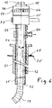
- FIG. 6 shows an example in which the fixing tube 11 can simultaneously be brought to the treatment site with precision.
- the fixing tube 11 ' is designed as a nucleoscope with an extraction nozzle 50.
- a further tube namely an outer guide tube 51 is required, which is optionally equipped with a body spacer 20 and which serves to guide the axially displaceable fixing tube 11 '.
- the inner diameter of the fixing tube 11 ' is dimensioned so large that a gap 52 remains between the bendable guide tube 12 or other cylindrical instrumentation through which the fluid to be extracted can reach the suction nozzle 50 from the point to be treated.
- a suction device is connected to the suction nozzle.
- the gap 52 can be combined in connection with another liquid supply channel to form a liquid circuit.
- the supply channel can be, for example, the channel 46 provided in the microendoscope 18 '.
- the channel 52 of the nucleoscope can of course also be used as a supply and suction line.
- the fixing tube 11 ' is in this case axially displaceably connected to a fixation device 21' for the operating table and can be locked in the selected position by means of a rotary knob 53.
- a manually operable feed device 54 for the fixing tube 11 ' is connected to the fixation device 21' and has a rotating ring 55 with an associated scale 56.
- the feed mechanism can be, for example, a screw-nut system with a correspondingly fine thread, the rotary ring 55 forming the nut.
- FIG. 7 shows an application of a guide instrument 10 for the treatment of a herniated disc, the guide instrument 10 essentially being composed of a combination of the components shown in FIGS. 5 and 6.
- an outer guide tube 51 ' is pushed in by hand until it stops against the annulus 70.
- the fixing tube 11 'equipped with the fixation device 21 or 21' and positioning device 56 comes into the outer guide tube 51 '.
- the Positioning device 56 With the Positioning device 56, the penetration depth of the fixing tube 11 'in the intervertebral disc 71 is precisely adjusted and locked.
- the bendable guide tube 12 with the microendoscope 18 'contained therein is inserted into the fixation tube 11', rotated with the rotating ring 24 so that the bend direction of the articulated end piece 13 faces the treatment site 16 ', precisely advanced and locked by means of the feed device 19'.
- the end piece 13 is curved with the lever 23 in such a way that the guide tube outlet points to the treatment site 16 '.
- the area 16 ′ of the intervertebral disk 71 is first softened by means of laser beams, the size of the area to be irradiated being selected accordingly by the options described in connection with FIG. 4.
- the softened tissue of the intervertebral disc 71 is then suctioned through the channel 25 of the fixing tube 11 '(FIG. 6).
- a rinsing process is carried out via a circuit.
- the rinsing agent is introduced into the treatment site through the supply nozzle 63 and, for example, via a channel 46 (FIG. 2) located in the microendoscope 18 'and via a channel separate from it, e.g. vacuumed the gap 52 (FIG. 6) between the bendable guide tube 12 and the fixation tube 11 '.
- the free end face 72 of the outer guide tube 51 ′ is designed as a sealing element in order to seal the opening 73 in the annulus 70 with respect to the surrounding muscle tissue 48.
- the guide instrument 10 constitutes a structural unit, the various positioning devices being connected to one another by means of corresponding closures.
- handling is carried out in the immediate vicinity of the patient.
- part of the positioning devices can be moved to an equipment table in order to facilitate the controlled handling of the operating elements and thus ensure that the intervention is successful.
- the instrument set could be separated at line 75, so that the microendoscope 18 ', the laser probe 17 and the irrigation can be operated from an equipment table, the flexible microendoscope 18' being the connection between the manufactures parts of the guide instrument located on the patient or device table.
- the instruments used for this purpose can be designed with the associated positioning devices in such a way that they can be assembled into a complete structural unit before they are inserted into a fixed guide tube located on the patient. This will minimize the amount of manipulation required during the procedure.
- Various instruments can also be designed with the associated positioning devices in such a way that they can be assembled as desired, ie with correspondingly matched connecting elements. It is also possible to have at least one Part of the positioning devices not to be adjusted manually, but via a control device.
- the control unit can be operated via parameters to be set or with control signals that are output by a computer.
- the invention is not limited to the examples described above, but rather extends to all embodiments with which the precise placement of instruments using a guide instrument is possible.
Landscapes
- Health & Medical Sciences (AREA)
- Life Sciences & Earth Sciences (AREA)
- Surgery (AREA)
- Physics & Mathematics (AREA)
- Veterinary Medicine (AREA)
- Optics & Photonics (AREA)
- Nuclear Medicine, Radiotherapy & Molecular Imaging (AREA)
- Public Health (AREA)
- General Health & Medical Sciences (AREA)
- Engineering & Computer Science (AREA)
- Biomedical Technology (AREA)
- Heart & Thoracic Surgery (AREA)
- Medical Informatics (AREA)
- Molecular Biology (AREA)
- Animal Behavior & Ethology (AREA)
- Pathology (AREA)
- Radiology & Medical Imaging (AREA)
- Biophysics (AREA)
- Electromagnetism (AREA)
- Otolaryngology (AREA)
- Neurology (AREA)
- Orthopedic Medicine & Surgery (AREA)
- Laser Surgery Devices (AREA)
- Endoscopes (AREA)
Abstract
Es wird zur perutenen Behandlung von Gewebeteilen, insbesondere Bandscheiben ein Führungsinstrument (10) vorgeschlagen, das im wesentlichen aus einem Führungsrohr (12) mit einem abwinkelbaren Endstück(13) und Betätigungseinrichtungen (14, 15, 19, 22, 24) besteht, die am distalen Ende mit dem Führungsrohr verbunden sind und zum Abwinkeln des Endstückes, sowie für den Vorschub von im Rohr geführten Instrumentarien (17, 18) dienen. <IMAGE>
Description
- Die Erfindung bezieht sich auf ein Instrument zur perkutanen Behandlung von Gewebeteilen mit einem Führungsinstrument für Instrumentarien.
- Es sind Führungsinstrumente für sogenannte monoportale perkutane Behandlungen bekannt, die ein Führungsrohr enthalten, die unter Rötgenkontrolle bis zum behandelnden Gewebe geschoben werden. Durch dieses Führungsrohr wird je nach Behandlung eine Sonde, Lasersonde oder anderweitiges Instrumentarium, z.B. eine Faßzange zur Entfernung von Gewebe, geführt. Diese Behandlung erfolgt ohne direkte Sicht auf das zu behandelnde oder zu entfernende Gewebe, EP 438 241.
- Abhilfe hierzu schafft das biportale Verfahren, bei dem ein zweites Führungsrohr verwendet wird, durch das die Optik bis zur Behandlungsstelle geführt wird. Hierzu ist jedoch ein zweiter Einstich erforderlich, der überdies schwierig zu handhaben ist.
- Es besteht in beiden Fällen die Schwierigkeit, die Sonde oder ein Endoskop genau zu positionieren.
- Der Erfindung liegt die Aufgabe zugrunde, hier Abhilfe zu schaffen, insbesondere ein Führungsinstrument zu entwickeln, mit dem das Gewebe mit Präzision und bei Bedarf kleinräumig behandelt werden kann.
- Die Aufgabe wird erfindungsgemäß mit den Merkmalen des Anspruchs 1 gelöst.
- Durch am Führungsinstrument vorgesehene Betätigungsmittel, mit denen die Instrumentarien präzise an den Behandlungsort geführt werden können, ist eine Behandlung sowohl qualitativ als auch zeitlich durch vereinfachte und genau einstellbare Handhabung in wesentlich verbesserter Form möglich. Diese Betätigungsmittel sind für feinjustierbare Bewegungen ausgestaltet und am äußeren Ende des Führungsintrumentes angebracht, wo sie durch Handhabung durch den Chirurgen, z.B. Drehen, Schieben von Drehknöpfen, Hebeln in eine feingradige Dreh- oder Längsbewegung des am proximalen Ende herausragenden Instrumentariums umgesetzt werden. An Skalen kann der Bewegungsgrad der Instrumentarien abgelesen werden. Mittels Fixierknöpfen werden die in die Eingriffsstellung gebrachten Instrumentarien arretiert.
- Um eine exakte und während des Eingriffs stabile Plazierung der Instrumentarien zu ermöglichen, ist das Führungsinstrument mit einem Fixierrohr ausgestattet, das nach der Einführung in das Gewebe mit einer Fixationseinrichtung an einem Operationstisch fixiert wird. Das Fixierrohr dient somit als Führungs- und Bewegungsreferenz für die übrigen Instrumentarien. Das Fixierrohr kann je nach Anwendung das äußerste Führungsrohr bilden oder innerhalb eines anderweitigen äußeren Führungsrohres mittels einer Positioniereinrichtung führbar ausgebildet sein.
- Gemäß einer weiteren Ausgestaltung der Erfindung ist ein Führungsrohr mit abwinkelbarem Rohrendstück vorgesehen, das mit Betätigungsmitteln abgewinkelt werden kann. Hiermit ist es möglich, die Instrumentarien, wie z.B. Sonden, Lasersonden und/oder Mikroendoskopen auch an nicht direkt erreichbare Behandlungsstellen führen zu können. Dieses ist beispielsweise von Bedeutung bei der Behandlung von Bandscheibenvorfällen, wobei nicht alle Bereiche direkt mit einer geradlinigen Sonde oder einem geradlinigen Führungsinstrument erreicht werden können. Abwinkelbare Rohre sind bereits bekannt. Eine Ausführung ist beispielsweise in der DE 42 22 121 beschrieben.
- Das abwinkelbare Führungsrohr wird vorzugsweise, ausgestattet mit einer Positioniereinrichtung, innerhalb des Fixierrohres geführt, wobei es selbst zur Führung und exakten Plazierung weiterer Instrumentarien in einer Umgebung außerhalb der Instrumenten-Achslinie dient. Die proximalen Enden von Instrumentarien, wie Lasersonden, Endoskopen, Zangen, die aus dem krümmbaren Endstück des Führungsrohres herausragen, lassen sich auf diese Weise präzise dreidimensional bewegen und somit genau auf die zu behandelnde Stelle führen, auch wenn diese Stelle nicht in der Verlängerung des Führungsinstrumentes liegt. Bei Behandlungen mit Lasersonden, wie z.B. in der Nucleotomie, hat die Erfindung darüber hinaus den Vorteil, daß die Dosierung der Laserenergie aufgrund der Verkürzung des Abstandes zwischen Sonde und dem zu behandelnden Gewebe gegenüber herkömmlichen Verfahren stark reduziert werden kann. Die im Führungsrohr geführten Instrumentarien sind vorzugsweise ebenfalls mit Positioniereinrichtungen ausgestattet.
- Das Führungsinstrument ist insbesondere für die perkutane Nucleotomie sowohl mit einem abwinkelbaren Rohrendstück als auch mit von Hand betätigbaren Mechanismen ausgerüstet, mit denen ein Vorschub und eine Drehung der im Führungsrohr befindlichen Instrumentarien während einer Behandlung durchführbar ist.
- Dem Führungsinstrument ist gemäß einer weiteren Ausgestaltung der Erfindung ein Nucleoskop mit einem Anschlußstück für Saug- und Spülgeräte zugeordnet, so daß die verschiedenen Behandlungsvorgänge, einschließlich Ausspülen und Absaugen, in einer raschen Folge hintereinander durchführbar sind. Als Nucleoskop kann ein Fixierrohr verwendet werden, das mit entsprechender Ausgestaltung das Führungsrohr unter Beibehaltung eines Ringspaltes zur Bildung eines Flüssigkeits-Kanals umgibt.
- Vorzugsweise wird für den Transport von Flüsigkeiten ein Spülkreislauf durch das Führungsinstrument verwendet. Damit wird nicht nur eine rasch durchführbare, sondern auch eine qualitativ hochwertige Spülung bzw. Absaugung der Behandlungsstelle ermöglicht. Der Spülkreislauf läßt sich fertigungstechnisch einfach durch einen Kanal innerhalb eines internen Instrumentariums, z.B. Endoskop, und einen Ringkanal realisieren, der z.B.zwischen dem Fixationsrohr oder einem internen Instrumentarium, wie dem abwinkelbaren Führungsrohr, sich befindet.
- Nach einer weiteren Ausgestaltung der Erfindung ist ein Endoskop oder Mikroendoskop mit integrierter Lasersonde vorgesehen, wobei die Lasersonde getrennt vom Endoskop bewegbar ist. Eine derartige Ausführung läßt sich auch zur großräumigen Bestrahlung ausstatten. Dies kann durch eine Lasersonde mit senkrechter oder schräger Strahlenaustrittfläche erreicht werden, die exzentrisch im Endoskop angeordnet ist. Durch Rotation der Lasersonde oder des Endoskops beschreibt die Strahlenaustrittfläche unterschiedlich große Kreise, womit unterschiedlich große Strahlenfelder bewirkt werden können.
- Die Erfindung wird anhand von in der Zeichnung schematisch dargestellten Ausführungsbeispielen näher beschrieben. Es zeigen:
- Fig. 1 ein Instrument in seiner Gesamtheit,
- Fig. 2 eine Vorschubeinrichtung,
- Fig. 3 ein Datail aus Fig. 1,
- Fig. 4 Feldgrößen von Laserbestrahlungen,
- Fig. 5 Endoskop mit Laser-Vorschubeinrichtung und
- Fig. 6 und 7 je ein weiteres Ausführungsbeispiel.
- Fig. 1 zeigt eine Gesamtvorrichtung für eine monoportale perkutane Behandlung, bestehend im wesentlichen aus einem Führungsintrument 10 und einem Geräteanschluß 10'. Das Führungsinstrument 10 weist ein äußeres Fixierrohr 11 und ein darin enthaltenes abwinkelbares Führungsrohr 12 auf, dessen proximales Endstück 13 mittels einer Betätigungseinrichtung 14 bis etwa 90° abwinkelbar und mittels einer Dreheinrichtung 15 innerhalb des Fixierrohres 11 um die Längsache dreh- und fixierbar ist. Durch dieses Führungsrohr 12 werden die Instrumentarien, die für die jeweilige Behandlung erforderlich sind, bis zur Behandlungsstelle 16 geführt. In Fig. 1 sind als Instrumentarien eine Lasersonde 17 und ein Mikroendoskop 18, z.B. bekannter Bauart, gezeigt. Es können auch andere Instrumentarien, wie Zangen, Abtraggeräte, Sonden, Spüleinrichtungen und ähnliches, mit dem Führungsrohr 12 geführt und positioniert werden. Am Geräteanschluß 10' ist eine Kaltlichtquelle 30 und eine Optik 31, z.B. Videokamera, sowie eine nicht dargestellte Laserquelle anschließbar. Der Geräteanschluß 10' wird je nach Bedarf ausgebildet und mit den für den jeweiligen Eingriff notwendigen Geräten, z.B. Optikeinrichtungen, mechanische Geräte zur Betätigung von Instrumentarien, wie Bohrer, Raspeln etc., verbunden.
- Dem Führungsinstrument 10 sind ferner Betätigungsmittel zur genauen Positionierung der durch das Führungsrohr 12 geführten Instrumentarien zugeordnet. Der Vorschub des Führungsrohres 12 erfolgt je nach Anwendung direkt manuel oder mittels einer manuell bedienbaren mechanischen Vorschubeinrichtung, wie sie beispielsweise mit dem Bezugszeichen 19 gekennzeichnet und in Fig. 5 vergrößert dargestellt ist.
- Ein Ausführungsbeispiel einer Vorschubeinrichtung 19 ist in vereinfachter Darstellung in Fig. 2 gezeigt. Die Vorschubeinrichtung 19 enthält vier Zahnwalzen 34, die über ein Zahnräderwerk 35 mit einer mit dem Zahnräderwerk 35 verbundenen Welle 37 und einem Drehring 38 in Drehverbindung stehen. Die Zahnwalzen 34 liegen mit einem entsprechenden Druck an dem präzise vorzuschiebenen Instrumentarium, z.B. dem Mikroendoskop 18, an und werden dieses bei entsprechender Drehung der Zahnwalzen 34 vor oder zurückschieben. Der Vorschub wird an einer in Verbindung mit dem Drehring 38 stehenden Skala 39 abgelesen. Fig. 2a zeigt einen Längsschnitt der Vorschubeinrichung 19 quer zu den Zahnwalzen 34. Die Fig. 2b ist ein Längsschnitt senkrecht zu Fig. 2a.
- Je nach Anwendung werden dem Führungsintrument 10 ein oder mehrere Positioniereinrichtungen für verschiedene Instrumentarien und/oder Führungsrohre zugeordnet, die mittels Bajonett-, Schraub- oder anderen Verschlüssen entsprechend der jeweiligen Anwendung miteinander koppelbar sind und Teil des Führungsinstrumentes 10 bilden. Dabei sind die Instrumentarien entweder gruppenweise gemeinsam oder je getrennt innerhalb eines Führungsrohres 12 dreh-, vorschieb- oder zurückziehbar. Gemäß Fig. 1 beispielsweise ist für die Lasersonde 17 eine gesonderte Positioniereinrichtung 22 vorgesehen, mit der die Lasersonde 17 getrennt vom Mikroendoskop 18 um seine Längsachse gedreht und in Längsrichtung vorgeschoben werden kann. Es ist natürlich auch möglich, die Lasersonde 17 mit dem Mikroendoskop 18 so zu verbinden, daß beide Instrumente nur gemeinsam bewegt werden können.
- Mit den manuell mittels Hebeln 23, Drehknöpfen 61,66 oder Drehringen 24,38,55,62, 65 bedienbaren Positioniereinrichtungen 14,15,19,22,54 können die Instrumentarien feinfühlig bedient und demzufolge präzise (unter röntgenografischer Beobachtung) an die vorgesehene Behandlungsstelle 16 geführt werden. Mit Fixierknöpfen 25 bis 29, 53 werden die Instrumentarien schließlich in den eingebrachten Stellungen bei Bedarf fixiert.
- Das nach Bedarf zusammensetzbare Führungsinstrument 10 ist durch die feingradige und genaue Führbarkeit auch außerhalb der Instrumenten-Achslinie für microinvasive perkutane Behandlungen besonders gut geeignet. Die proximalen Instrumentenenden lassen sich durch Kombination von Drehbewegungen und exzentrischen Anordnungen darüber hinaus über größere Bereiche am Behandlungsort bewegen. Ein Beispiel hierzu wird nachfolgend unter Bezugnahme auf die Figuren 3 und 4 erläutert.
- Fig. 3 zeigt in vergrößerter Darstellung das proximale Ende 32 (siehe Fig. 1) des Führungsinstrumentes 10. Aus dem Ende des Fixierrohres 11 ragt das in eine Krümmungsstellung gebrachte biegbare Endstück 13 des Führungsrohres 12 heraus. In diesem wird das Mikroendoskop 18 geführt, das gleichzeitig die Lasersonde 17 mit exzentrischer Anordnung trägt, die in der dargestellten Ausführung eine schräge Strahlenaustrittfläche 40 hat. Durch die Exzentrizität der Lasersonde 17 und die individuelle Bewegungmöglichkeit der beiden Instrumentarien 17 und 18 sind unterschiedlich große Feldbereiche bestrahlbar.
- Fig. 4a bis 4d zeigen vier unterschiedliche, mit Laserstrahlen einwirkbare Bereiche des zu behandelnden Gewebes. Der kleinstmögliche Feldbereich 42 wird durch eine nicht bewegte Lasersonde 17 mit senkrechter Austrittsfläche 41, wie in Fig. 4a gezeigt ist, oder schräger Austrittsfläche 40 erreicht. Mit einer schrägen Austrittsfläche 40 kann der Feldbereich 43 durch Rotation der Lasersonde 17 vergrößert werden, Fig.4b.
- Weitere Vergrößerungen erreicht man, wenn eine Lasersonde 17 mit quergerichteter Austrittsfläche 41 (Fig. 4c, Feldbereich 44) bzw. mit schräger Austrittsfläche 40 (Fig. 4d, Feldbereich 45) mit dem Mikroendoskop 12 um die Führungsinstrumenten-Achse 33' bewegt wird. Dabei ist der Feldbereich 45 größer als der Feldbereich 44.
- In Fig. 5 ist eine Ausführung eines Mikroendoskopes 18' mit integrierter Lasersonde 17' dargestellt, mit dem unterschiedlich große Feldbereiche behandelt werden können. An einem Geräteanschluß 10'' ist eine Positioniereinrichtung 60 mit einem Drehknopf 61 für den Vorschub und einem Drehring 62 für die Rotationsbewegung des Mikroendoskops 18' verbunden. Die Optik 31 für das Mikroendoskop 18' schließt sich an der Stirnseite des Geräteanschlußes 10'' an. Schräg am Außenumfang mündet die Lasersonde 17 mit der Vorschub- und Rotationseinrichtung 22' in den Geräteanschluß 10'' ein, worin die Lasersonde 17 in das Mikroendoskop 18' eingeführt ist. In dem Mikroendoskop 18' ist ferner ein Kanal 46 (Fig. 3) zur Einführung von Lösungen, Spülmitteln, usw. vorgesehen, der mit einem Anschlußstutzen 63 am Geräteanschluß 10'' in Verbindung steht. Ferner ist ein Kaltlichtanschluß 64 angebracht.
- Das äußere Fixierrohr 11 dient zur Fixierung des Führungsinstrumentes 10 am menschlichen Körper. Dazu ist eine Körperdistanzscheibe 20, die sich am Körper abstützt und mit dem durch eine zentrische Bohrung geführten Fixierrohr 11 verbindbar und mittels eines Fixierknopfes 25 arretierbar ist, und eine Fixationsvorrichtung 21 vorgesehen, über die das Fixierrohr 11 andererseits mit dem OP-Tisch befestigt wird.
- Fig. 6 zeigt ein Beispiel, bei dem das Fixierrohr 11 gleichzeitig mit Präzision an die Behandlungsstelle heranführbar ist. Dieses ist beispielsweise erforderlich, wenn das Fixierrohr 11' als Nucleoscop mit einem Absaugstutzen 50 ausgebildet ist. In derartigen Fällen ist ein weiteres Rohr, nämlich ein äußeres Führungsrohr 51 erforderlich, das ggf. mit einer Körperdistanzscheibe 20 ausgerüstet ist und das zur Führung des axial verschiebbaren Fixierrohres 11' dient. Der innere Durchmesser des Fixierrohres 11' ist so groß bemessen, daß zwischen dem darin geführten krümmbaren Führungsrohr 12 oder einem anderweitigen zylindrischen Instrumentarium ein Spalt 52 verbleibt, über den abzusaugendes Fluid von der zu behandelden Stelle zum Absaugstutzen 50 gelangen kann. Mit dem Absaugstutzen wird eine nicht dargestellte Absaugeinrichtung verbunden. Der Spalt 52 läßt sich in Verbindung mit einem anderweitigen Flüssigkeitszufuhrkanal zu einem Flüssigkeitskreislauf kombinieren. Der Zufuhrkanal kann beispielsweise der im Mikroendoskop 18' vorgesehene Kanal 46 sein. Der Kanal 52 des Nucleoskops kann selbstverständlich auch als Zufuhr- und Absaugleitung benutzt werden.
- Das Fixierrohr 11' ist in diesem Fall axial verschiebbar mit einer Fixationsvorrichtung 21' für den OP-Tisch verbunden und mittels eines Drehknopfes 53 in der gewählten Stellung arretierbar. Mit der Fixationsvorrichtung 21' ist eine von Hand betätigbare Vorschubeinrichtung 54 für das Fixierrohr 11' verbunden, die einen Drehring 55 mit zugehöriger Skala 56 aufweist. Der Vorschubmechanismus kann beispielsweise ein Schraube-Mutter-System mit entsprechend feinem Gewinde sein, wobei der Drehring 55 die Mutter bildet.
- Fig. 7 zeigt eine Anwendung eines Führungsinstrumentes 10 zur Behandlung eines Bandscheibenvorfalles, wobei das Führungsintrument 10 sich im wesentlichen aus einer Kombination der in Figuren 5 und 6 dargestellten Bestandteile zusammensetzt.
- Nach der Vorbereitung eines Einführkanals durch Muskelgewebe 48 mit bekannten Mitteln und Verfahren und dem Durchstoßen des Faserringes bzw. äußeren Annulus 70 wird ein äußeres Führungsrohr 51' bis zum Anschlag an den Annulus 70 von Hand eingeschoben. In das äußere Führungsrohr 51' kommt das mit der Fixationsvorrichtung 21 oder 21' und Positioniereinrichtung 56 ausgestattete Fixierrohr 11'. Mit der Positioniereinrichtung 56 wird die Eindringtiefe des Fixierrohres 11' in der Bandscheibe 71 genau eingestellt und arretiert. Anschließend wird das abwinkelbare Führungsrohr 12 mit dem darin enthaltenen Mikroendoskop 18' in das Fixierrohr 11' eingeführt, mit dem Drehring 24 so gedreht, daß die Abwinkelrichtung des gegliederten Endstücks 13 zur Behandlungsstelle 16' zeigt, mittels der Vorschubeinrichtung 19' präzise vorgeschoben und arretiert. Schließlich wird das Endstück 13 mit dem Hebel 23 gekrümmt, derart, daß der Führungsrohraustritt zur Behandlungsstelle 16' zeigt. Das Mikroendoskop 18' enthält die Lasersonde 17 entsprechend Fig.5.
- In dieser Stellung ist es dann möglich, mit den Arbeitsinstrumentarien zur Behandlungsstelle zu gelangen und die Behandlung durchzuführen. Bei einem Bandscheibenvorfall wird der Bereich 16' der Bandscheibe 71 zunächst mittels Laserstrahlen aufgeweicht, wobei die Größe des zu bestrahlenden Bereiches entsprechend durch die in Verbindung mit Fig. 4 beschriebenen Möglichkeiten gewählt wird. Anschließend wird das aufgeweichte Gewebe der Bandscheibe 71 durch den Kanal 25 des Fixierrohres 11' (Fig. 6) abgesaugt.
- Ein ggf. erforderlicher Spülvorgang wird über einen Kreislauf durchgeführt. D.h. das Spülmittel wird durch den Zuführstutzen 63 und über beispielsweise einen im Mikroendoskop 18' befindlichen Kanal 46 (Fig. 2) in die Behandlungsstelle eingebracht und über einen davon getrennten Kanal, z.B. den Spalt 52 (Fig. 6) zwischen dem krümmbaren Führungsrohr 12 und dem Fixationsrohr 11' wieder abgesaugt. Um einen Austritt von Spülmitteln aus dem Bandscheibenbereich in das Muskelgewebe 48 zu vermeiden, ist das freie Stirnende 72 des äußeren Führungsrohres 51' als Abdichtungselement ausgebildet, um den Durchbruch 73 im Annulus 70 gegenüber dem umgebenden Muskelgewebe 48 abzudichten.
- Gemäß Fig. 7 stellt das Führungsinstrument 10 nach dem Zusammensetzen der einzelnen Komponenten (Instrumentarien, Positioniereinrichtungen) eine Baueinheit dar, wobei die verschiedenen Positioniereinrichtungen über entsprechende Verschlüße miteinander verbunden sind. Die Handhabung erfolgt in so einem Fall unmittelbar in der Nähe des Patienten. Für längere Eingriffe kann ein Teil der Positioniereinrichtungen zu einem Gerätetisch verlagert werden, um die kontrollierte Handhabung der Bedienungselemente zu erleichtern und damit ein Gelingen des Eingriffs sicherzustellen. Bei dem in Fig. 7 gezeigten Beispiel, könnte dazu das Insrumentarium an der Linie 75 getrennt werden, so daß das Mikroendoskop 18', die Lasersonde 17 und die Spülung von einen Gerätetisch aus bedient werden, wobei das flexible Mikroendoskop 18' die Verbindung zwischen den am Patienten bzw Gerätetisch befindlichen Teilen des Führungsinstruments herstellt.
- Für häufig vorkommende Eingriffe können die dazu verwendeten Instrumentarien mit den zugehörigen Positioniereinrichtungen so ausgestaltet werden, daß sie vor deren Einführung in ein am Patienten befindlichen, fixierten Führungrohr zu einer kompletten Baueinheit zusammengesetzt werden können. Dadurch werden die erforderlichen Handgriffe während des Eingriffes minimieren. Verschiedene Instrumentarien können mit den zugehörigen Positioniereinrichtungen auch so ausgebildet werden, daß sie beliebig, d.h. mit entsprechend abgestimmten Verbindungselementen, zusammensetzbar sind. Außerdem ist es möglich, zumindest einen Teil der Positioniereinrichtungen nicht per Hand, sondern über eine Steuervorrichtung einzustellen. Das Steuergerät kann dabei über einzustellende Parametern oder mit Steuersignalen betrieben werden, die von einem Rechner ausgegeben werden.
- Die Erfindung ist nicht auf die vorstehend beschriebenen Beispiele beschränkt, sie erstreckt sich vielmehr auf alle Ausführungsformen, mit denen die genaue Plazierung von Instrumentarien unter Anwendung eines Führungsinstrumentes möglich ist.
Claims (9)
- Instrument zur perkutanen Behandlung von Gewebeteilen mit einem Führungsinstrument für Instrumentarien, dadurch gekennzeichnet, daß das Führungsinstrument (10) Betätigungsmittel (14,15,19,22,56,60) aufweist, mit denen die Instrumentarien (12,17,18,18') längs verschiebbar und/oder um deren Längsachse (33) drehbar sind und damit präzise an die Behandlungsstelle (16,16') führbar sind.
- Instrument nach Anspruch 1, dadurch gekennzeichnet, daß das Führungsinstrument (10) zusätzlich Fixiereinrichtungen (21,21',25 - 28) aufweist, mit denen die Instrumentarien (12,17,18,18') in der eingebrachten Stellung und das Führungsinstrument (10) gegenüber einem OP-Tisch fixierbar sind.
- Instrument nach Anspruch 1 oder 2, dadurch gekennzeichnet, daß dem Führungsinstrument (10) ein Fixationsrohr (11,11') und ein in dem Fixationsrohr mit Präzision führbares Führungsrohr (12) mit abwinkelbarem proximalen Endstück (13) zugeordnet ist.
- Instrument nach einem der vorhergehenden Ansprüche, dadurch gekennzeichnet, daß das Führungsinstrument (10) mit einem Spülkreislauf (63,46,52,50) ausgestattet ist.
- Instrument nach einem der vorhergenhenden Ansprüche, dadurch gekennzeichnet, daß konzentrisch ineinander geführte Instrumentarien (12,17,18,18') je gesonderte, als Positioniereinrichtungen ausgestaltete Betätigungsmittel (14,15,19,22,54,56,60) zugeordnet sind, mit denen die Instrumentarien je getrennt in Länsrichtung des Führungsinstruments (10) verschoben und/oder um die Längsachse (33) gedreht werden können.
- Instrument nach Anspruch 1 oder 5, dadurch gekennzeichnet, daß die Betätigungsmittel (14,15,19,22,54,56,60) mit Skalen (39,54) ausgestattet und so ausgebildet sind, daß kontrollierte stufenlose Verschiebungen und Drehungen der Instrumentarien (12,17,18,18') möglich sind und/oder daß die Instrumentarien mit rasterartige Bewegungen im Millimeterbereich betätigbar sind.
- Instrument nach Anspruch 1, 5 oder 6, dadurch gekennzeichnet, daß zumindest ein Teil der Betätigungsmittel (15,19,22',60)mit Fixierknöpfen (25-29,53) versehen sind, mit denen die Instrumentarien(12,17,18,18') in ihren ausgerichteten Positionen fixierbar sind.
- Instrument nach einem der vorhergehenden Ansprüche, dadurch gekennzeichnet, daß als Intrumentarium ein Endoskop oder Mikroendoskop (18,18') mit integrierter Lasersonde (17) und ggf. einem Kanal (46) zur Führung von Flüssigkeiten vorgesehen ist.
- Instrument nach Anspruch 5, dadurch gekennzeichnet, daß die Lasersonde (17) im Endoskop (18,18') exzentrisch angeordnet ist und daß dem Endoskop und der Lasersonde getrennte Betätigungsmittel (60 bzw.22') zugeordnet sind.
Applications Claiming Priority (2)
| Application Number | Priority Date | Filing Date | Title |
|---|---|---|---|
| DE4417637A DE4417637A1 (de) | 1994-05-19 | 1994-05-19 | Instrument zur perkutanen Behandlung von Gewebeteilen |
| DE4417637 | 1994-05-19 |
Publications (1)
| Publication Number | Publication Date |
|---|---|
| EP0682910A1 true EP0682910A1 (de) | 1995-11-22 |
Family
ID=6518528
Family Applications (1)
| Application Number | Title | Priority Date | Filing Date |
|---|---|---|---|
| EP95103395A Withdrawn EP0682910A1 (de) | 1994-05-19 | 1995-03-09 | Instrument zur perkutanen Behandlung von Gewebeteilen |
Country Status (2)
| Country | Link |
|---|---|
| EP (1) | EP0682910A1 (de) |
| DE (1) | DE4417637A1 (de) |
Cited By (46)
| Publication number | Priority date | Publication date | Assignee | Title |
|---|---|---|---|---|
| WO1998017190A3 (en) * | 1996-10-23 | 1998-10-22 | Oratec Interventions Inc | Method and apparatus for treating intervertebral discs |
| WO1999047058A3 (en) * | 1998-03-19 | 1999-11-11 | Oratec Interventions Inc | Catheter for delivery of energy to a surgical site |
| WO2000011999A1 (de) * | 1998-08-28 | 2000-03-09 | Storz-Endoskop Gmbh | Seitenblick-endoskop |
| US6246913B1 (en) | 1997-02-14 | 2001-06-12 | Oractec Interventions, Inc. | Method and apparatus for the treatment of strabismus |
| US6290715B1 (en) | 1996-08-13 | 2001-09-18 | Oratec Interventions, Inc. | Method for delivering energy adjacent the inner wall of an intervertebral disc |
| WO2001074259A1 (de) * | 2000-03-30 | 2001-10-11 | Siemens Aktiengesellschaft | Medizinische einrichtung mit einer antriebseinrichtung für eine nadel |
| US6350262B1 (en) | 1997-10-22 | 2002-02-26 | Oratec Interventions, Inc. | Method and apparatus for applying thermal energy to tissue asymetrically |
| US6391028B1 (en) | 1997-02-12 | 2002-05-21 | Oratec Interventions, Inc. | Probe with distally orientated concave curve for arthroscopic surgery |
| US6461353B1 (en) | 1995-02-17 | 2002-10-08 | Oratec Interventions, Inc. | Orthopedic apparatus for controlled contraction of collagen tissue |
| US6461357B1 (en) | 1997-02-12 | 2002-10-08 | Oratec Interventions, Inc. | Electrode for electrosurgical ablation of tissue |
| US6482204B1 (en) | 1994-05-06 | 2002-11-19 | Oratec Interventions, Inc | Method and apparatus for controlled contraction of soft tissue |
| WO2002098314A1 (en) * | 2001-06-06 | 2002-12-12 | Oratec Interventions, Inc. | Intervertebral disc device employing prebent sheath |
| US6645203B2 (en) | 1997-02-12 | 2003-11-11 | Oratec Interventions, Inc. | Surgical instrument with off-axis electrode |
| US6695839B2 (en) | 2001-02-08 | 2004-02-24 | Oratec Interventions, Inc. | Method and apparatus for treatment of disrupted articular cartilage |
| US6726685B2 (en) | 2001-06-06 | 2004-04-27 | Oratec Interventions, Inc. | Intervertebral disc device employing looped probe |
| US6733496B2 (en) | 2001-06-06 | 2004-05-11 | Oratec Interventions, Inc. | Intervertebral disc device employing flexible probe |
| EP1459692A1 (de) * | 1996-10-23 | 2004-09-22 | Oratec Interventions, Inc. | Verfahren und vorrichtung zur behandlung von zwischenwirbelscheiben |
| US6878155B2 (en) | 2000-02-25 | 2005-04-12 | Oratec Interventions, Inc. | Method of treating intervertebral disc tissue employing attachment mechanism |
| US7150747B1 (en) | 2003-01-22 | 2006-12-19 | Smith & Nephew, Inc. | Electrosurgical cutter |
| JP2007511292A (ja) * | 2003-11-13 | 2007-05-10 | シナージエテイクス・インコーポレイテツド | 調節可能な照明領域を有する照明レーザプローブ |
| WO2007097797A3 (en) * | 2006-02-21 | 2008-03-13 | Boston Scient Scimed Inc | Positioning system for manipulating a channel within a medical device |
| US7449019B2 (en) | 1999-01-25 | 2008-11-11 | Smith & Nephew, Inc. | Intervertebral decompression |
| EP1615574A4 (de) * | 2003-04-09 | 2009-02-11 | Synergetics Inc | Direktionale lasersonde |
| DE102008029301A1 (de) * | 2008-06-19 | 2009-12-24 | Richard Wolf Gmbh | Endoskop- und Schaftsystem |
| US7658765B2 (en) | 1999-08-18 | 2010-02-09 | Intrinsic Therapeutics, Inc. | Resilient intervertebral disc implant |
| US7717961B2 (en) | 1999-08-18 | 2010-05-18 | Intrinsic Therapeutics, Inc. | Apparatus delivery in an intervertebral disc |
| US7727241B2 (en) | 2003-06-20 | 2010-06-01 | Intrinsic Therapeutics, Inc. | Device for delivering an implant through an annular defect in an intervertebral disc |
| US7749275B2 (en) | 1999-08-18 | 2010-07-06 | Intrinsic Therapeutics, Inc. | Method of reducing spinal implant migration |
| US7867278B2 (en) | 1999-08-18 | 2011-01-11 | Intrinsic Therapeutics, Inc. | Intervertebral disc anulus implant |
| US7959679B2 (en) | 1999-08-18 | 2011-06-14 | Intrinsic Therapeutics, Inc. | Intervertebral anulus and nucleus augmentation |
| US7972337B2 (en) | 2005-12-28 | 2011-07-05 | Intrinsic Therapeutics, Inc. | Devices and methods for bone anchoring |
| US8231678B2 (en) | 1999-08-18 | 2012-07-31 | Intrinsic Therapeutics, Inc. | Method of treating a herniated disc |
| US8323341B2 (en) | 2007-09-07 | 2012-12-04 | Intrinsic Therapeutics, Inc. | Impaction grafting for vertebral fusion |
| US8454612B2 (en) | 2007-09-07 | 2013-06-04 | Intrinsic Therapeutics, Inc. | Method for vertebral endplate reconstruction |
| US8470043B2 (en) | 2008-12-23 | 2013-06-25 | Benvenue Medical, Inc. | Tissue removal tools and methods of use |
| ITTO20131059A1 (it) * | 2013-12-23 | 2015-06-24 | Fond Istituto Italiano Di Tecnologia | Sistema ottico integrato per un'apparecchiatura microendoscopica. |
| US9161773B2 (en) | 2008-12-23 | 2015-10-20 | Benvenue Medical, Inc. | Tissue removal tools and methods of use |
| US9335455B2 (en) | 2012-05-30 | 2016-05-10 | Cygnus, LP | Extended tip laser and illumination probe for retina surgery |
| US9370447B2 (en) * | 2011-10-10 | 2016-06-21 | Cygnus LP | Probes for use in ophthalmic and vitreoretinal surgery |
| GB2561860A (en) * | 2017-04-25 | 2018-10-31 | Imperial Innovations Ltd | Micromanipulation apparatus for clinical application |
| US10314605B2 (en) | 2014-07-08 | 2019-06-11 | Benvenue Medical, Inc. | Apparatus and methods for disrupting intervertebral disc tissue |
| US11471145B2 (en) | 2018-03-16 | 2022-10-18 | Spinal Elements, Inc. | Articulated instrumentation and methods of using the same |
| US11564811B2 (en) | 2015-02-06 | 2023-01-31 | Spinal Elements, Inc. | Graft material injector system and method |
| US11583327B2 (en) | 2018-01-29 | 2023-02-21 | Spinal Elements, Inc. | Minimally invasive interbody fusion |
| US11771483B2 (en) | 2017-03-22 | 2023-10-03 | Spinal Elements, Inc. | Minimal impact access system to disc space |
| USRE49994E1 (en) | 2013-03-14 | 2024-06-04 | Spinal Elements, Inc. | Spinal fusion implants and devices and methods for deploying such implants |
Families Citing this family (3)
| Publication number | Priority date | Publication date | Assignee | Title |
|---|---|---|---|---|
| DE19815119C1 (de) * | 1998-04-03 | 2000-01-05 | Braun Melsungen Ag | Antriebsvorrichtung für eine elastische Sonde, insbesondere medizinische Sonde |
| DE19933278C2 (de) | 1999-07-14 | 2001-11-29 | Biotronik Mess & Therapieg | Steuerbarer Katheter |
| US7294135B2 (en) * | 2003-03-20 | 2007-11-13 | Medtronic Vascular, Inc | Control handle for intraluminal devices |
Citations (3)
| Publication number | Priority date | Publication date | Assignee | Title |
|---|---|---|---|---|
| DE9109933U1 (de) * | 1991-08-10 | 1991-10-17 | Aesculap AG, 7200 Tuttlingen | Applikator für chirurgische Zwecke |
| CH680041A5 (en) * | 1989-05-23 | 1992-06-15 | Gerard Barki | Endoscope with optical fibre illumination and viewing - includes control head sliding axially and rotating on main body to allow adjustment of position |
| WO1993020742A1 (en) * | 1992-04-08 | 1993-10-28 | Danek Medical, Inc. | Endoscope for direct visualization of the spine and epidural space |
Family Cites Families (8)
| Publication number | Priority date | Publication date | Assignee | Title |
|---|---|---|---|---|
| US3557780A (en) * | 1967-04-20 | 1971-01-26 | Olympus Optical Co | Mechanism for controlling flexure of endoscope |
| US3610231A (en) * | 1967-07-21 | 1971-10-05 | Olympus Optical Co | Endoscope |
| US4758222A (en) * | 1985-05-03 | 1988-07-19 | Mccoy William C | Steerable and aimable catheter |
| SU1489735A1 (ru) * | 1987-11-23 | 1989-06-30 | Mo Med Stomatolog | Устройство для разделения внутричерепных структур |
| DE3840749A1 (de) * | 1988-12-03 | 1990-06-07 | Koscher & Wuertz Gmbh | Vorrichtung zum einfuehren einer lasersonde in einen koerper |
| CA2034013A1 (en) * | 1990-01-12 | 1991-07-13 | Tor G. Larsen | Means for inserting instrumentation for a percutaneous diskectomy using a laser |
| AU6835990A (en) * | 1990-01-12 | 1991-08-01 | Laserscope | Instrumentation clamp |
| SU1741786A1 (ru) * | 1990-03-26 | 1992-06-23 | Ташкентский государственный медицинский институт | Устройство дл эндохоледохеальной папиллосфинктеротомии |
-
1994
- 1994-05-19 DE DE4417637A patent/DE4417637A1/de not_active Withdrawn
-
1995
- 1995-03-09 EP EP95103395A patent/EP0682910A1/de not_active Withdrawn
Patent Citations (3)
| Publication number | Priority date | Publication date | Assignee | Title |
|---|---|---|---|---|
| CH680041A5 (en) * | 1989-05-23 | 1992-06-15 | Gerard Barki | Endoscope with optical fibre illumination and viewing - includes control head sliding axially and rotating on main body to allow adjustment of position |
| DE9109933U1 (de) * | 1991-08-10 | 1991-10-17 | Aesculap AG, 7200 Tuttlingen | Applikator für chirurgische Zwecke |
| WO1993020742A1 (en) * | 1992-04-08 | 1993-10-28 | Danek Medical, Inc. | Endoscope for direct visualization of the spine and epidural space |
Cited By (96)
| Publication number | Priority date | Publication date | Assignee | Title |
|---|---|---|---|---|
| US6482204B1 (en) | 1994-05-06 | 2002-11-19 | Oratec Interventions, Inc | Method and apparatus for controlled contraction of soft tissue |
| US6461353B1 (en) | 1995-02-17 | 2002-10-08 | Oratec Interventions, Inc. | Orthopedic apparatus for controlled contraction of collagen tissue |
| US8226697B2 (en) | 1996-08-13 | 2012-07-24 | Neurotherm, Inc. | Method for treating intervertebral disc |
| US7400930B2 (en) | 1996-08-13 | 2008-07-15 | Oratec Interventions, Inc. | Method for treating intervertebral discs |
| US7267683B2 (en) | 1996-08-13 | 2007-09-11 | Oratec Interventions, Inc. | Method for treating intervertebral discs |
| US6290715B1 (en) | 1996-08-13 | 2001-09-18 | Oratec Interventions, Inc. | Method for delivering energy adjacent the inner wall of an intervertebral disc |
| US8187312B2 (en) | 1996-08-13 | 2012-05-29 | Neurotherm, Inc. | Method for treating intervertebral disc |
| US7647123B2 (en) | 1996-08-13 | 2010-01-12 | Oratec Interventions, Inc. | Method for treating intervertebral discs |
| US8128619B2 (en) | 1996-08-13 | 2012-03-06 | Neurotherm, Inc. | Method for treating intervertebral discs |
| US6547810B1 (en) | 1996-08-13 | 2003-04-15 | Oratec Interventions, Inc. | Method for treating intervertebral discs |
| US6997941B2 (en) | 1996-08-13 | 2006-02-14 | Oratec Interventions, Inc. | Method and apparatus for treating annular fissures in intervertebral discs |
| US6517568B1 (en) | 1996-08-13 | 2003-02-11 | Oratec Interventions, Inc. | Method and apparatus for treating intervertebral discs |
| US7282061B2 (en) | 1996-08-13 | 2007-10-16 | Oratec Interventions, Inc. | Method of treating intervertebral disc |
| US6749605B2 (en) | 1996-10-23 | 2004-06-15 | Oratec Interventions, Inc. | Catheter for delivery of energy to a surgical site |
| US6258086B1 (en) | 1996-10-23 | 2001-07-10 | Oratec Interventions, Inc. | Catheter for delivery of energy to a surgical site |
| JP2002515793A (ja) * | 1996-10-23 | 2002-05-28 | オーレイテック インターヴェンションズ インコーポレイテッド | 椎間円板を治療するための方法及び装置 |
| US7309336B2 (en) | 1996-10-23 | 2007-12-18 | Oratec Interventions, Inc. | Catheter for delivery of energy to a surgical site |
| EP1459691A1 (de) * | 1996-10-23 | 2004-09-22 | Oratec Interventions, Inc. | Verfahren und vorrichtung zur behandlung von zwischenwirbelscheiben |
| WO1998017190A3 (en) * | 1996-10-23 | 1998-10-22 | Oratec Interventions Inc | Method and apparatus for treating intervertebral discs |
| EP1459692A1 (de) * | 1996-10-23 | 2004-09-22 | Oratec Interventions, Inc. | Verfahren und vorrichtung zur behandlung von zwischenwirbelscheiben |
| US6767347B2 (en) | 1996-10-23 | 2004-07-27 | Oratec Interventions, Inc. | Catheter for delivery of energy to a surgical site |
| US6645203B2 (en) | 1997-02-12 | 2003-11-11 | Oratec Interventions, Inc. | Surgical instrument with off-axis electrode |
| US6461357B1 (en) | 1997-02-12 | 2002-10-08 | Oratec Interventions, Inc. | Electrode for electrosurgical ablation of tissue |
| US6391028B1 (en) | 1997-02-12 | 2002-05-21 | Oratec Interventions, Inc. | Probe with distally orientated concave curve for arthroscopic surgery |
| US6246913B1 (en) | 1997-02-14 | 2001-06-12 | Oractec Interventions, Inc. | Method and apparatus for the treatment of strabismus |
| US6350262B1 (en) | 1997-10-22 | 2002-02-26 | Oratec Interventions, Inc. | Method and apparatus for applying thermal energy to tissue asymetrically |
| WO1999047058A3 (en) * | 1998-03-19 | 1999-11-11 | Oratec Interventions Inc | Catheter for delivery of energy to a surgical site |
| WO2000011999A1 (de) * | 1998-08-28 | 2000-03-09 | Storz-Endoskop Gmbh | Seitenblick-endoskop |
| US7449019B2 (en) | 1999-01-25 | 2008-11-11 | Smith & Nephew, Inc. | Intervertebral decompression |
| US7959679B2 (en) | 1999-08-18 | 2011-06-14 | Intrinsic Therapeutics, Inc. | Intervertebral anulus and nucleus augmentation |
| US7998213B2 (en) | 1999-08-18 | 2011-08-16 | Intrinsic Therapeutics, Inc. | Intervertebral disc herniation repair |
| US8257437B2 (en) | 1999-08-18 | 2012-09-04 | Intrinsic Therapeutics, Inc. | Methods of intervertebral disc augmentation |
| US8025698B2 (en) | 1999-08-18 | 2011-09-27 | Intrinsic Therapeutics, Inc. | Method of rehabilitating an anulus fibrosus |
| US8021425B2 (en) | 1999-08-18 | 2011-09-20 | Intrinsic Therapeutics, Inc. | Versatile method of repairing an intervertebral disc |
| US9706947B2 (en) | 1999-08-18 | 2017-07-18 | Intrinsic Therapeutics, Inc. | Method of performing an anchor implantation procedure within a disc |
| US8002836B2 (en) | 1999-08-18 | 2011-08-23 | Intrinsic Therapeutics, Inc. | Method for the treatment of the intervertebral disc anulus |
| US8231678B2 (en) | 1999-08-18 | 2012-07-31 | Intrinsic Therapeutics, Inc. | Method of treating a herniated disc |
| US8409284B2 (en) | 1999-08-18 | 2013-04-02 | Intrinsic Therapeutics, Inc. | Methods of repairing herniated segments in the disc |
| US7879097B2 (en) | 1999-08-18 | 2011-02-01 | Intrinsic Therapeutics, Inc. | Method of performing a procedure within a disc |
| US7867278B2 (en) | 1999-08-18 | 2011-01-11 | Intrinsic Therapeutics, Inc. | Intervertebral disc anulus implant |
| US7658765B2 (en) | 1999-08-18 | 2010-02-09 | Intrinsic Therapeutics, Inc. | Resilient intervertebral disc implant |
| US9333087B2 (en) | 1999-08-18 | 2016-05-10 | Intrinsic Therapeutics, Inc. | Herniated disc repair |
| US7717961B2 (en) | 1999-08-18 | 2010-05-18 | Intrinsic Therapeutics, Inc. | Apparatus delivery in an intervertebral disc |
| US7749275B2 (en) | 1999-08-18 | 2010-07-06 | Intrinsic Therapeutics, Inc. | Method of reducing spinal implant migration |
| US6878155B2 (en) | 2000-02-25 | 2005-04-12 | Oratec Interventions, Inc. | Method of treating intervertebral disc tissue employing attachment mechanism |
| US7069087B2 (en) | 2000-02-25 | 2006-06-27 | Oratec Interventions, Inc. | Apparatus and method for accessing and performing a function within an intervertebral disc |
| WO2001074259A1 (de) * | 2000-03-30 | 2001-10-11 | Siemens Aktiengesellschaft | Medizinische einrichtung mit einer antriebseinrichtung für eine nadel |
| US7175635B2 (en) | 2000-03-30 | 2007-02-13 | Siemens Aktiengesellschaft | Medical device with a drive unit for a needle |
| US6695839B2 (en) | 2001-02-08 | 2004-02-24 | Oratec Interventions, Inc. | Method and apparatus for treatment of disrupted articular cartilage |
| US6726685B2 (en) | 2001-06-06 | 2004-04-27 | Oratec Interventions, Inc. | Intervertebral disc device employing looped probe |
| WO2002098314A1 (en) * | 2001-06-06 | 2002-12-12 | Oratec Interventions, Inc. | Intervertebral disc device employing prebent sheath |
| US6638276B2 (en) | 2001-06-06 | 2003-10-28 | Oratec Interventions, Inc. | Intervertebral disc device employing prebent sheath |
| US6733496B2 (en) | 2001-06-06 | 2004-05-11 | Oratec Interventions, Inc. | Intervertebral disc device employing flexible probe |
| US7150747B1 (en) | 2003-01-22 | 2006-12-19 | Smith & Nephew, Inc. | Electrosurgical cutter |
| EP1615574A4 (de) * | 2003-04-09 | 2009-02-11 | Synergetics Inc | Direktionale lasersonde |
| US7727241B2 (en) | 2003-06-20 | 2010-06-01 | Intrinsic Therapeutics, Inc. | Device for delivering an implant through an annular defect in an intervertebral disc |
| US7972326B2 (en) | 2003-11-13 | 2011-07-05 | Synergetics, Inc. | Illuminated laser probe with adjustable area of illumination |
| JP2007511292A (ja) * | 2003-11-13 | 2007-05-10 | シナージエテイクス・インコーポレイテツド | 調節可能な照明領域を有する照明レーザプローブ |
| EP1686910A4 (de) * | 2003-11-13 | 2010-02-10 | Synergetics Inc | Beleuchtete lasersonde mit verstellbarem beleuchtungsbereich |
| US9610106B2 (en) | 2005-12-28 | 2017-04-04 | Intrinsic Therapeutics, Inc. | Bone anchor systems |
| US10470804B2 (en) | 2005-12-28 | 2019-11-12 | Intrinsic Therapeutics, Inc. | Bone anchor delivery systems and methods |
| US8394146B2 (en) | 2005-12-28 | 2013-03-12 | Intrinsic Therapeutics, Inc. | Vertebral anchoring methods |
| US7972337B2 (en) | 2005-12-28 | 2011-07-05 | Intrinsic Therapeutics, Inc. | Devices and methods for bone anchoring |
| US11185354B2 (en) | 2005-12-28 | 2021-11-30 | Intrinsic Therapeutics, Inc. | Bone anchor delivery systems and methods |
| US9039741B2 (en) | 2005-12-28 | 2015-05-26 | Intrinsic Therapeutics, Inc. | Bone anchor systems |
| US8114082B2 (en) | 2005-12-28 | 2012-02-14 | Intrinsic Therapeutics, Inc. | Anchoring system for disc repair |
| US9179825B2 (en) | 2006-02-21 | 2015-11-10 | Boston Scientific Scimed, Inc. | Positioning system for manipulating a channel within a medical device |
| WO2007097797A3 (en) * | 2006-02-21 | 2008-03-13 | Boston Scient Scimed Inc | Positioning system for manipulating a channel within a medical device |
| US7815564B2 (en) | 2006-02-21 | 2010-10-19 | Boston Scientific Scimed, Inc. | Positioning system for manipulating a channel within a medical device |
| US8795156B2 (en) | 2006-02-21 | 2014-08-05 | Boston Scientific Scimed, Inc. | Methods for manipulating a channel within a medical device |
| US8454612B2 (en) | 2007-09-07 | 2013-06-04 | Intrinsic Therapeutics, Inc. | Method for vertebral endplate reconstruction |
| US10716685B2 (en) | 2007-09-07 | 2020-07-21 | Intrinsic Therapeutics, Inc. | Bone anchor delivery systems |
| US9226832B2 (en) | 2007-09-07 | 2016-01-05 | Intrinsic Therapeutics, Inc. | Interbody fusion material retention methods |
| US8361155B2 (en) | 2007-09-07 | 2013-01-29 | Intrinsic Therapeutics, Inc. | Soft tissue impaction methods |
| US8323341B2 (en) | 2007-09-07 | 2012-12-04 | Intrinsic Therapeutics, Inc. | Impaction grafting for vertebral fusion |
| US10076424B2 (en) | 2007-09-07 | 2018-09-18 | Intrinsic Therapeutics, Inc. | Impaction systems |
| US9597113B2 (en) | 2008-06-19 | 2017-03-21 | Richard Wolf Gmbh | Endoscope and shaft system |
| DE102008029301A1 (de) * | 2008-06-19 | 2009-12-24 | Richard Wolf Gmbh | Endoskop- und Schaftsystem |
| US9161773B2 (en) | 2008-12-23 | 2015-10-20 | Benvenue Medical, Inc. | Tissue removal tools and methods of use |
| US8470043B2 (en) | 2008-12-23 | 2013-06-25 | Benvenue Medical, Inc. | Tissue removal tools and methods of use |
| US9370447B2 (en) * | 2011-10-10 | 2016-06-21 | Cygnus LP | Probes for use in ophthalmic and vitreoretinal surgery |
| US9335455B2 (en) | 2012-05-30 | 2016-05-10 | Cygnus, LP | Extended tip laser and illumination probe for retina surgery |
| USRE49994E1 (en) | 2013-03-14 | 2024-06-04 | Spinal Elements, Inc. | Spinal fusion implants and devices and methods for deploying such implants |
| ITTO20131059A1 (it) * | 2013-12-23 | 2015-06-24 | Fond Istituto Italiano Di Tecnologia | Sistema ottico integrato per un'apparecchiatura microendoscopica. |
| WO2015097598A1 (en) * | 2013-12-23 | 2015-07-02 | Fondazione Istituto Italiano Di Tecnologia | Integrated optical system for a microendescopic apparatus |
| US10314605B2 (en) | 2014-07-08 | 2019-06-11 | Benvenue Medical, Inc. | Apparatus and methods for disrupting intervertebral disc tissue |
| US11224453B2 (en) | 2014-07-08 | 2022-01-18 | Spinal Elements, Inc. | Apparatus and methods for disrupting intervertebral disc tissue |
| US12053196B2 (en) | 2014-07-08 | 2024-08-06 | Spinal Elements, Inc. | Apparatus and methods for disrupting inter vertebral disc tissue |
| US11564811B2 (en) | 2015-02-06 | 2023-01-31 | Spinal Elements, Inc. | Graft material injector system and method |
| US12121456B2 (en) | 2015-02-06 | 2024-10-22 | Spinal Elements, Inc. | Graft material injector system and method |
| US11771483B2 (en) | 2017-03-22 | 2023-10-03 | Spinal Elements, Inc. | Minimal impact access system to disc space |
| GB2561860A (en) * | 2017-04-25 | 2018-10-31 | Imperial Innovations Ltd | Micromanipulation apparatus for clinical application |
| US11583327B2 (en) | 2018-01-29 | 2023-02-21 | Spinal Elements, Inc. | Minimally invasive interbody fusion |
| US12207856B2 (en) | 2018-01-29 | 2025-01-28 | Spinal Elements, Inc. | Minimally invasive interbody fusion |
| US11471145B2 (en) | 2018-03-16 | 2022-10-18 | Spinal Elements, Inc. | Articulated instrumentation and methods of using the same |
| US12357291B2 (en) | 2018-03-16 | 2025-07-15 | Spinal Elements, Inc. | Articulated instrumentation and methods of using the same |
Also Published As
| Publication number | Publication date |
|---|---|
| DE4417637A1 (de) | 1995-11-23 |
Similar Documents
| Publication | Publication Date | Title |
|---|---|---|
| DE4417637A1 (de) | Instrument zur perkutanen Behandlung von Gewebeteilen | |
| DE69200571T2 (de) | Vorrichtung zum Bohren von Löchern zur Implantation von Verriegelungsnägeln für Marknägel. | |
| EP1523932B1 (de) | Endoskop | |
| DE69321723T2 (de) | Endoskop zum sichtbarmachen des spinal- und epidural-raumes | |
| DE3504292C1 (de) | Instrument fuer endoskopische Eingriffe,insbesondere zur perkutanen Gallensteinentfernung oder Gallenblasenveroedung | |
| DE3206782C2 (de) | Chirurgisches Instrument | |
| DE3500444C2 (de) | Vorrichtung zum Einführen eines Endoskops oder eines chirurgischen Werkzeugs in Körperhöhlen mit einer Zufuhr für ein Spülmedium und einer Absaugung für dieses Spülmedium | |
| EP0405132B1 (de) | Winkelaufsatz | |
| DE4033916C2 (de) | ||
| DE69919857T2 (de) | Wirbelkörper-Distraktor | |
| DE112018006968B4 (de) | Endoskop | |
| DE3852753T2 (de) | Instrument zur Venenklappenresektion mit optischem System. | |
| EP0605764A1 (de) | Instrument zum Implantieren und Extrahieren von Stents | |
| DE19748579A1 (de) | Endoskopisches Instrument | |
| EP3641670B1 (de) | Instrumenten-set für wirbelsäulenoperationen | |
| DE3917663C2 (de) | ||
| DE10358817B3 (de) | Endoskop | |
| DE102021108057A1 (de) | Drehbare gewebeprobennahmevorrichtung | |
| DE3936811A1 (de) | Instrument zur endoskopischen entfernung von gallensteinen und dergleichen | |
| DE19515626C2 (de) | Instrument zum Positionieren wenigstens einer Arbeitshülse | |
| EP4046583B1 (de) | Elektrochirurgisches handgerät und kontaktkörper für elektrochirurgisches handgerät | |
| DE3345612A1 (de) | Stichsonde fuer perkutane nephroskopie | |
| DE102018006442A1 (de) | Instrumenten-Set | |
| DE4240182A1 (de) | Vorrichtung zum kontrollierten Abtragen von Material und insbesondere biologischem Gewebe | |
| DE9416957U1 (de) | Vorrichtung zur Führung und Fixierung chirurgischer Instrumente |
Legal Events
| Date | Code | Title | Description |
|---|---|---|---|
| PUAI | Public reference made under article 153(3) epc to a published international application that has entered the european phase |
Free format text: ORIGINAL CODE: 0009012 |
|
| AK | Designated contracting states |
Kind code of ref document: A1 Designated state(s): CH DE FR GB IT LI |
|
| RAP1 | Party data changed (applicant data changed or rights of an application transferred) |
Owner name: BERTAGNOLI, RUDOLF, DR.MED. Owner name: TIEBER, FRIEDRICH |
|
| 17P | Request for examination filed |
Effective date: 19951207 |
|
| 17Q | First examination report despatched |
Effective date: 19970409 |
|
| STAA | Information on the status of an ep patent application or granted ep patent |
Free format text: STATUS: THE APPLICATION IS DEEMED TO BE WITHDRAWN |
|
| 18D | Application deemed to be withdrawn |
Effective date: 19980210 |