EP0682921B1 - Pièce à main médicale ou dentaire - Google Patents
Pièce à main médicale ou dentaire Download PDFInfo
- Publication number
- EP0682921B1 EP0682921B1 EP95107675A EP95107675A EP0682921B1 EP 0682921 B1 EP0682921 B1 EP 0682921B1 EP 95107675 A EP95107675 A EP 95107675A EP 95107675 A EP95107675 A EP 95107675A EP 0682921 B1 EP0682921 B1 EP 0682921B1
- Authority
- EP
- European Patent Office
- Prior art keywords
- sleeve
- grip
- handpiece
- handpiece according
- grooves
- Prior art date
- Legal status (The legal status is an assumption and is not a legal conclusion. Google has not performed a legal analysis and makes no representation as to the accuracy of the status listed.)
- Expired - Lifetime
Links
Images

Classifications
-
- A—HUMAN NECESSITIES
- A61—MEDICAL OR VETERINARY SCIENCE; HYGIENE
- A61C—DENTISTRY; APPARATUS OR METHODS FOR ORAL OR DENTAL HYGIENE
- A61C1/00—Dental machines for boring or cutting ; General features of dental machines or apparatus, e.g. hand-piece design
- A61C1/08—Machine parts specially adapted for dentistry
-
- A—HUMAN NECESSITIES
- A61—MEDICAL OR VETERINARY SCIENCE; HYGIENE
- A61C—DENTISTRY; APPARATUS OR METHODS FOR ORAL OR DENTAL HYGIENE
- A61C1/00—Dental machines for boring or cutting ; General features of dental machines or apparatus, e.g. hand-piece design
- A61C1/08—Machine parts specially adapted for dentistry
- A61C1/16—Protecting caps for hand-pieces or angle-pieces
Definitions
- the invention relates to a medical or dental handpiece with a Grip sleeve that extends straight or angularly and at its front end a tool holder with a jig for a cross or along the Longitudinal axis of the handpiece arranged treatment tool, and on its rear end releasably by a coupling device with a supply part is connectable, the grip sleeve in her gripped by an operating hand Grip area a surface structure to improve the grip strength on their Has outer surface.
- a handpiece according to the preamble of claim 1 is known from the US-A-3,955,284.
- a handpiece should be easy to use, so that the practitioner can do it without great effort and attention easily grab and treat hold and lead. This requirement is essential because of it the quality of the treatment is dependent, the quality of the treatment of the human or animal body have lasting positive or negative consequences can.
- a handpiece should be light so that the practitioner can use it without much effort Can lead to exertion.
- several surface structures e.g. projections arranged in a ring (DE 31 42 534 C2) lying one against the other trough-shaped flats (DE-GM 79 10 126) and in the surface of the Grains embedded in the handpiece (EP-0 054 653 A2).
- an existing handpiece is a product whose Manufacturing costs should be low, so that the treatment costs are low can be held.
- the invention has for its object a medical or dental handpiece of the present type so that the handling while ensuring a safe guidance is easier to carry out.
- the subclaims contain features that govern the handling of the handpiece further improve, to simple and inexpensive to manufacture smaller designs Lead size, simplify assembly and disassembly and also Open up possibilities by varying the assembly with a handpiece to create different characteristics, in particular tool speeds.
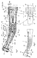
- the handpiece 1 is a replaceable part in the present embodiment a dental treatment instrument 2, the handpiece 1 and a Supply part 3 comprises, to which the handpiece 1 with its rear end by a Plug-in / rotary coupling 4 is easy to use and can be coupled quickly, and that connectable to a supply system by a rear supply line 5 that is the drive energy and treatment media for the treatment instrument 2 provides that by extending in the flexible connecting line 5 Supply lines are supplied.
- the drive motor 6 for one at the front head end of the handpiece 1 Clamping device 7 clampable treatment tool 8, here a drill, is as Electric motor arranged in the supply part 3 and by one in the handpiece 1 axially extending and rotatably mounted drive shaft train 9 with a Tool 8 receiving bearing sleeve 11 is drivingly connected.
- the tool 8 is transverse to the longitudinal central axis of the handpiece 1 in a handpiece head 10 with the Bearing sleeve 11 rotatably mounted, and it thus points to the so-called tool side.
- the plug-in / rotary coupling 4 is by a cylindrical coupling pin 12 and hollow cylindrical coupling recess 13 is formed, in which the coupling pin 12th can be inserted and releasably locked in the inserted position, wherein in the locked position, the rotatability of the handpiece 1 on the coupling pin 12 is guaranteed.
- the pressable latching device 14 is by a in one Recess of the coupling pin 12 or the coupling recess 13 stored locking element biased by a spring or formed by a spring 15, e.g. a spring ring, formed in a corresponding annular Locking groove 16 is able to snap into place.
- the coupling pin 12 is on the supply part 3 arranged, from which it projects axially, while the coupling recess 13 in Handpiece 1 is arranged and is open to the rear.
- the drive shaft train 9 instructs at its rear end a plug-in coupling part 17, which in the axial Assembling the handpiece 1 and the supply part 3 automatically with one corresponding mating connector part (not shown) on the supply part 3 can be coupled.
- the coupling pin 12 is formed by a sleeve open at the front, in which when plugging together the rear end region of the drive shaft train 9 is inserted so that the coupling pin 12 which is in the coupling recess 13 extends over the drive shaft train 9.
- the main parts of the handpiece 1 shaped in the form of a so-called elbow are a grip sleeve 18, the front end portion by an acute angle W of is angled about 21 ° to the side facing away from the tool 8, a rear Reinforcement sleeve 19, in particular made of metal, which from the rear into the grip sleeve 18th usable and fixable therein by a fixing device 21, a front one Reinforcement sleeve 22 in particular made of metal, which is from the front in a cylindrical hole the grip sleeve 18 can be used and can be fixed therein by a fixing device 23 which the tool 8 receiving and rotatably mounted handpiece head 10, which with a rear cylindrical plug-in coupling pin 24 from the front into the front Reinforcement sleeve 22 can be used and in it by a fixing device 25 against one unintentional pulling out and secured against rotation, the Drive shaft train 9, which consists of a rear drive shaft part 9a, which extends up to Kink point 26 of the grip sle
- the Drive shaft parts 9a, 9b are by two bevel gears 31a, 31b mounted thereon Area of the inflection point 26 connected to one another by drive.
- a step-up or step-down gear 32 can be integrated 1 as a structural unit with the rear Reinforcing sleeve 19 connected and thus can be installed and removed with this.
- the front drive shaft part 9b is in an axial bearing bore of the Plug-in coupling pin picked up and stored.
- the grip sleeve 18 has a Centering and a shoulder surface 33a against which the rear reinforcing sleeve 19 can be tensioned on the gear 32 with a corresponding shoulder surface 33b.
- This is a ring nut 34 is provided, which with an external thread 35a in a rear End of the grip sleeve 18 arranged internal thread 35b can be screwed in and with a Shoulder surface 36a against a rearward-facing shoulder surface 36b on the Reinforcing sleeve 19 presses.
- these are Shoulder surface pair 36a, 36b forward divergent conical surfaces that center form for the reinforcement sleeve 19 in the rear region of the grip sleeve 18.
- a second Centering for the front area of the rear reinforcement sleeve 19 is in the middle Area of the grip sleeve 18 provided, in the embodiment according to FIG. 1 directly behind the break point 26, and it is through a coaxial, cylindrical hole 37 in Area of an inner ring projection 38 with the rearward-pointing approximately radial Shoulder surface 33a formed.
- the transmission 32 is in an inner housing 41 arranged as a unit with a rear thread 42nd is screwed to the front end of the rear reinforcement sleeve 19, is preferably screwed on.
- the inner housing 41 has at its front end a cylindrical projection 43 which fits in the hole 37 and thus centers is.
- the fixing device 23 for the handpiece head 10 is by a locking screw 45 formed with a particularly conical locking lug, which from the outside in a their screw head 47 and receiving a cylindrical hole 48 Threaded hole 49 of the front reinforcing sleeve 22 is screwed in and with it in particular conical locking lug in a correspondingly shaped cap 51 in Plug-in coupling pin 24 can be screwed in.
- a locking screw 45 formed with a particularly conical locking lug, which from the outside in a their screw head 47 and receiving a cylindrical hole 48 Threaded hole 49 of the front reinforcing sleeve 22 is screwed in and with it in particular conical locking lug in a correspondingly shaped cap 51 in Plug-in coupling pin 24 can be screwed in.
- the media line 28 passes through the plug / rotary coupling 4 radially in such a way that in the flow is guaranteed in every rotary position.
- one opens axially parallel and then radially extending media channel 53, 54 on the Shell surface of the coupling pin 12, wherein in the rear reinforcing sleeve 19 in a radial media channel 55 continues in the same radial plane.
- Sealing the Gap between the coupling pin 12 and the coupling recess 13 takes place through arranged on both sides of the outlet or inlet openings Sealing rings 56, each in an outer groove of the coupling pin 12 or in an inner groove of the coupling recess 13 can sit.
- annular groove 55a arranged to in any rotational position to ensure the flow is in the transverse plane of the channel opening in the Outer lateral surface of the coupling pin 12 or in the inner lateral surface of the Coupling recess 13 an annular groove 55a arranged.
- the media channel section 55 extends to a round opening in the reinforcing sleeve 19 Hole 58, into which an angular connection tube 57 is firmly and tightly inserted, e.g. is soldered or glued.
- the bent pipe section 57a is approximately axially parallel or arranged slightly divergent to the outside, and it projects through and towers above Grip sleeve 18 in a through hole 61 to the outside and to the front.
- the hose 29 is plugged on.
- the tube section 57a passes through the grip sleeve 18 in the region of a radially extending wall 62, by a step-like cross-sectional expansion of the grip sleeve 18 or by a outer recess 63 can be formed in the grip sleeve 18.
- the recess 63 is dimensioned so large that the hose 29 can be plugged on.
- connection tube 57 is automatically installed in his when installing the rear reinforcement sleeve 19 Installation position brought outside on the grip sleeve, without it being a subsequent Sealing is required. This is due to the approximately axially parallel extension of the Pipe section 57a and the hole 61 allows.
- the front end of the hose 29 is on a second connection tube 64 (Fig. 2) attached, which is attached to the handpiece head 10 in a lateral position, e.g. soldered or is glued, and is bent so that its rear tube section 64a is approximately axially parallel is directed and its front tube section 64b is directed to the treatment site.
- the rear connection tube 57 is in the middle Position of the upper right or left (right-handed) quadrant in the viewing direction from behind (see Fig. 2).
- the grip sleeve 18 is used for the previously described different versions used, with the adaptation of the corresponding Cross-sectional dimension or for mounting the roller bearings 65 a radial spacer 69 is inserted into the grip sleeve 18, the outer cross-sectional dimension 71a with Fit to the inner cross-sectional dimension 71b of the grip sleeve 18 is adapted and of the shoulder surface 33a and be axially secured by suitable measures can.
- the spacer sleeve 69 can e.g.
- spacer sleeve 69 can be arranged so that the latter can be screwed in is.
- the ring shoulder 67 in one piece on the back on the spacer sleeve 69.
- gear 32 of different sizes or bearing elements can have several Spacer sleeves 69 each provided with an internal cross-section adapted to the size be.
- the surface shape and texture is in the grip area 72 the grip sleeve 18 is essential, since the grip strength is dependent on it.
- the grip strength is dependent on it.
- the Handpiece is stable and can be held securely in the hand of the user and not the attacking surfaces of the operating hand or its fingers should be overused. It should be noted that in the operation of the Handpiece low vibrations can hardly be excluded, which the Increased pressure on the handle surfaces.
- this requirement is met preferably two measures, namely a corrugated lateral surface and on the other hand, a slight roughness of the lateral surface in the grip area 72 the shape of the grip sleeve 18 has a significant impact on a comfortable and safe Holding and gripping the handpiece 1.
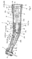
- the basic shape of the grip sleeve 18 in the grip area 72 is described below with reference to FIG. 4.
- the grip sleeve can be divided into four shaped sections 73, 74, 75, 76 from the back to the front.
- the first molding section 73 is thickened rearward divergently with respect to the second cylindrical molding section 74, this thickening being conical or initially slightly concave and then slightly convexly rounded, as shown in the figures.
- the third mold section 75 is located in the region of the kink point 26.
- the grip sleeve 18 is curved and at the same time tapers towards the front in cross section, the ratio of the cross-sectional dimensions at the beginning and at the end of this mold section 75 being approximately 1.2 to 1 .
- the fourth mold section 76 is tapered concentrically in a conical shape towards the front end, the taper ratio in the region of the third mold section 75 and the fourth mold section 76 being approximately the same.
- the starting points p1 and p2 of the third and fourth mold sections 75, 76 on the convex side of the grip sleeve 18 are preferably offset somewhat to the rear with respect to the starting points p3 and p4.
- the outer diameter d1 of the grip sleeve 18 in the region of the second shaped section 74 is approximately 13 to 17 mm, in particular approximately 15.2 mm. From this cross-sectional dimension, the grip sleeve 18 tapers to an outer diameter d2 of approximately 7 to 11 mm, in particular approximately 9 mm, at its front end.
- the length of the first and second mold sections 73, 74 on the concave side of the grip sleeve 18, see l 1 is approximately 35 to 65 mm, preferably approximately 47.4 mm and on the convex side, see l 2 , approximately 20 to 55 mm , preferably about 41.3 mm.
- the average length l 3 of the fourth mold section 76 is approximately 12 to 20 mm, in particular approximately 15 mm.
- the start and end points p3, p4 of the third formal section 75 on the concave side of the grip sleeve 18 are at a distance l 4 from one another which is dimensioned somewhat less than the length l 3 , namely approximately 7 to 13 mm, in particular approximately 10 mm.
- the distance l 5 , l 6 of the kink point 26 arranged in the central region of the third mold section 75 from the rear or front end is approximately 40 to 70 mm, in particular approximately 50.5 mm or approximately 20 to 30 mm, in particular approximately 23.2 mm.
- the convergent lateral surface in the fourth mold section 76 closes with the associated one Longitudinal central axis an angle w1 of about 3 ° to 9 °, in particular about 6 ° 2.
- the grip area 72 which begins in the central area of the second mold section 74 and extends to the central region of the fourth mold section 76, that is Outer lateral surface 77 of the grip sleeve 18 preferably in the circumferential direction continuous grooves 78a or shafts 78b slightly undulated, which in cross section are concave or convex rounded and can have a sinusoidal shape.
- the radius r of the grooves 78a is equal to the radius r of the shafts 78b and is about 3 to 5 mm, in particular about 4 mm.
- the axial distance a between two adjacent grooves or shafts is about 2 to 4 mm, preferably about 3.1 mm.
- the mean flank angle w2 is approximately 10 to 30 °, in particular approximately 21 °. At Experiments have found that a groove depth t of approximately 0.05 to 0.3 mm, about 0.15 mm is particularly suitable.
- the shafts and grooves preferably run parallel to one another.
- Curvature can be several, e.g. four widened to the convex side in a wedge shape
- Compensating grooves or shafts 78a1, 78b1 can be provided.
- the shafts 78b are in the region of their flanks and / or Shaft crests, preferably the outer surface 77 in the grip area 72 as a whole, i.e. also the troughs or grooves 78a of low roughness, which are particularly evident in Connection with the curl is gentle on the skin of the operating hand and allows secure grip in the operating hand.
- the Corresponding outer lateral surface 77 over the entire length range of the grip sleeve 18 rough which makes the grip even when handling the handpiece 1, such as e.g. when gripping and plugging into the supply part 3, is improved.
- a roughness class K of about 1.5 to 4 ⁇ m, in particular about 2.24 ⁇ m (see VDI 3400 (VDI guidelines) is advantageously suitable.
- the grip sleeve 18 can be made of corrosion-resistant metal, in particular stainless steel, ceramic or preferably made of plastic, in particular fiber-reinforced plastic. It was also determined in the tests that polyether ether ketone (PEEK), in particular glass fiber or carbon fiber reinforced, is particularly suitable.
- PEEK polyether ether ketone
- the roughness is simple and inexpensive to produce, to mold them during manufacture by a corresponding roughness relevant mold surfaces of the mold.
- This manufacturing method is suitable in particular for fiber-reinforced materials, in particular plastic, as a result of which the Fibers remain embedded.
- the roughness or erosion structure through errosive processing to produce the outer surface 77.
- This can be an electroerrosive Machining, spark erosion, arc erosion or even eroding through successive selective burning by means of light beams, in particular Laser beams, or etching, act.
- the ripple or roughness according to the invention is required in the context of Invention extend only on the partial surfaces of the grip area 72, which of the Operating hand can be contacted.
- the manufacture of the plastic grip sleeve also allows it to be used in several through-dyed colors. This not only makes it special Color considerations of the practitioner take into account, but it is also possible that Colors to identify special designs of handpiece 1 or To use Instruments 2, e.g. special gear designs (speeds).
Landscapes
- Health & Medical Sciences (AREA)
- Oral & Maxillofacial Surgery (AREA)
- Dentistry (AREA)
- Epidemiology (AREA)
- Life Sciences & Earth Sciences (AREA)
- Animal Behavior & Ethology (AREA)
- General Health & Medical Sciences (AREA)
- Public Health (AREA)
- Veterinary Medicine (AREA)
- Dental Tools And Instruments Or Auxiliary Dental Instruments (AREA)
- Dental Preparations (AREA)
Claims (12)
- a) Pièce à main (1) médicale ou dentaireb) avec un manchon-poignée (18)c) qui est rectiligned) ou coudé,e) comporte à son extrémité antérieure un porte-outil (10) avec un dispositif de serrage (7) pour un outil (8) disposé dans la direction de l'axe longitudinal de la pièce à main (1) ou transversalement à celui-ci,f) et peut être couplé au niveau de son extrémité postérieure à une pièce d'alimentation (3) à l'aide d'un dispositif de couplage (4),g) - le manchon-poignée (18), dans sa partie poignée (72) qui peut être saisie par la main d'un utilisateur, présentant une structuration de surface améliorant la tenue en main, au moins dans des zones partielles adaptées de sa surface extérieure (77),h) - la structuration de surface étant formée de sillons (78a) et d'ondes (78b) qui s'étendent dans la direction périphérique, sont espacés les uns des autres d'une distance (a) et alternent les uns avec les autres,i) - les sillons et les ondes, en coupe axiale, étant arrondis concaves ou convexes, caractérisée par le fait quej) le rayon (r) des sillons (78a) et des ondes (78b) est identiquek) et est d'environ 3 à 5 mm,l) - la distance (a) entre deux sillons (78a) et ondes (78b) voisins étant comprise entre environ 2 et 4 mm,m) - et la profondeur des sillons (78a) et des ondes (78b) étant comprise entre 0,05 et 0,3 mm.
- Pièce à main selon la revendication 1, caractérisée par le fait que le rayon (r) des sillons (78a) et des ondes (78b) est d'environ 4 mm.
- Pièce à main selon la revendication 1 ou 2, caractérisée par le fait que la distance (a) entre deux sillons (78a) et ondes (78b) voisins est d'environ 3,1 mm.
- Pièce à main selon une des revendications précédentes, caractérisée par le fait que la profondeur des sillons (78a) est d'environ 0,15 mm.
- Pièce à main selon une des revendications précédentes, caractérisée par le fait que la surface extérieure (77) du manchon-poignée (18), dans la partie poignée (72) ou dans des zones partielles ou partout, est rugueuse avec une profondeur de rugosité allant de 1,5 à 3,5 µm, en particulier une rugosité d'environ 2,2 µm.
- Pièce à main selon une des revendications précédentes, caractérisée par le fait que la rugosité est obtenue par façonnage ou par érosion, en particulier par érosion fine.
- Pièce à main selon la revendication 1, caractérisée par le fait que le manchon-poignée est réalisé en un matériau façonnable dans un moule, en particulier en métal, en matière plastique ou en céramique.
- Pièce à main selon la revendication 1, caractérisée par le fait que dans la région d'extrémité postérieure et la région d'extrémité antérieure du manchon-poignée (18) sont montés des manchons de renfort (19, 22), le manchon de renfort postérieur (19) comportant les éléments de couplage (16) concernés pour le couplage par rotation/enfichage (4) et le porte-outil (10) pouvant être enfiché dans le manchon de renfort antérieur (22) par un embout de couplage (24) et pouvant être fixé à l'aide d'un dispositif de fixation (25).
- Pièce à main selon la revendication 8, caractérisée par le fait qu'elle comporte dans sa région médiane un trou intérieur cylindrique (37, 67) dans lequel la région d'extrémité antérieure du manchon de renfort postérieur (19) peut être montée et centrée le cas échéant à l'aide d'éléments de positionnement et/ou d'éléments de réducteur.
- Pièce à main selon la revendication 8, caractérisée par le fait que le manchon de renfort postérieur (19) peut être serré au moyen d'un élément de fixation inséré et bloqué dans le manchon-poignée (18), en particulier au moyen d'un élément (14) vissé, contre une surface d'épaulement (33a) aménagée dans le manchon-poignée (18) et tournée vers l'arrière ou est limité axialement par ladite surface d'épaulement.
- Pièce à main selon la revendication 8, caractérisée par le fait qu'il lui est associé au moins une douille d'espacement (69) radiale, en particulier en métal ou en matière plastique qui peut être montée de manière ajustée dans le manchon-poignée (18), dans la région de l'extrémité antérieure du manchon de renfort (19) et qui avec sa section intérieure libre forme un logement de palier (66) pour des éléments de réducteur et/ou des éléments de palier (65) d'un axe d'entraínement (9).
- Pièce à main selon la revendication 8, caractérisée par le fait que le dispositif de blocage (25) pour le porte-outil (10) est formé par un élément de blocage notamment en forme de tige, en particulier une vis de blocage (45), qui traverse le manchon-poignée (18) dans un trou radial (48), est inséré ou vissé depuis l'extérieur dans un trou (49) du manchon de renfort antérieur (19) et présente un têton de blocage de préférence conique qui pénètre dans un évidement de blocage (51) du porte-outil (10).
Applications Claiming Priority (2)
| Application Number | Priority Date | Filing Date | Title |
|---|---|---|---|
| DE4417810 | 1994-05-20 | ||
| DE4417810A DE4417810C2 (de) | 1994-05-20 | 1994-05-20 | Ärztliches oder zahnärztliches Handstück |
Publications (3)
| Publication Number | Publication Date |
|---|---|
| EP0682921A2 EP0682921A2 (fr) | 1995-11-22 |
| EP0682921A3 EP0682921A3 (fr) | 1996-03-13 |
| EP0682921B1 true EP0682921B1 (fr) | 1999-10-13 |
Family
ID=6518651
Family Applications (1)
| Application Number | Title | Priority Date | Filing Date |
|---|---|---|---|
| EP95107675A Expired - Lifetime EP0682921B1 (fr) | 1994-05-20 | 1995-05-18 | Pièce à main médicale ou dentaire |
Country Status (5)
| Country | Link |
|---|---|
| US (1) | US5674068A (fr) |
| EP (1) | EP0682921B1 (fr) |
| JP (1) | JP2873923B2 (fr) |
| AT (1) | ATE185478T1 (fr) |
| DE (2) | DE4417810C2 (fr) |
Families Citing this family (21)
| Publication number | Priority date | Publication date | Assignee | Title |
|---|---|---|---|---|
| EP1355580A1 (fr) * | 2000-12-18 | 2003-10-29 | Dentsply International, Inc. | Composants ameliores de piece a main de dentisterie |
| AU2003221594A1 (en) * | 2002-03-04 | 2003-09-16 | Sirona Dental Systems Gmbh | Dental hand instrument |
| WO2003083266A1 (fr) * | 2002-03-28 | 2003-10-09 | Dentsply International Inc. | Technique d'equilibrage d'elements rotatifs de turbine sur un instrument dentaire |
| CN1802130B (zh) * | 2003-03-13 | 2012-04-18 | 杰里·W·布朗宁 | 一次性牙科器件 |
| DE102005016049A1 (de) | 2005-04-07 | 2006-10-12 | Kaltenbach & Voigt Gmbh | Medizinisches Handstück mit einem abgewinkelten Schaft |
| USD551765S1 (en) * | 2005-04-26 | 2007-09-25 | Idmos Plc | Dental apparatus |
| US9144471B2 (en) * | 2005-07-26 | 2015-09-29 | Angstrom Manufacturing, Inc. | Prophy angle and adapter with guard |
| US8294224B2 (en) * | 2006-04-06 | 2012-10-23 | Micron Technology, Inc. | Devices and methods to improve carrier mobility |
| EP1880683A1 (fr) * | 2006-07-18 | 2008-01-23 | Bien-Air Holding SA | Système d'accouplement pour instrument à main à usage dentaire ou chirurgical |
| USD572822S1 (en) | 2006-09-21 | 2008-07-08 | Axenic Dental, Inc. | Disposable dental handpiece |
| USD580054S1 (en) | 2006-12-22 | 2008-11-04 | Axenic Dental, Inc. | Disposable dental handpiece |
| USD588698S1 (en) | 2007-02-21 | 2009-03-17 | Axenic Dental, Inc. | Disposable dental handpiece |
| JP5468002B2 (ja) | 2007-08-30 | 2014-04-09 | アセニック・デンタル・インコーポレーテッド | 使い捨て式歯科ハンドピース |
| CH699665A2 (fr) * | 2008-10-07 | 2010-04-15 | Bien Air Holding Sa | Piece a main a usage dentaire ou chirurgical. |
| FR2953435A1 (fr) * | 2009-12-04 | 2011-06-10 | Micro Mega Int Mfg Sa | Piece a main comprenant un corps comprenant une douille creuse |
| CN102883675A (zh) * | 2010-05-12 | 2013-01-16 | 比恩-空气控股有限公司 | 用于牙科或外科使用的电机和手持件之间的联接装置 |
| USD776814S1 (en) | 2015-06-11 | 2017-01-17 | Avid, Inc. | Dental prophy angle nosecone attachment feature |
| US9737375B2 (en) | 2015-06-11 | 2017-08-22 | Avid, Inc. | Dental handpiece and prophy angle |
| USD776815S1 (en) | 2015-06-11 | 2017-01-17 | Avid, Inc. | Dental handpiece nosecone |
| EP3202363B1 (fr) * | 2016-02-04 | 2023-07-19 | KaVo Dental GmbH | Outil dentaire et systeme dentaire |
| KR101823923B1 (ko) * | 2016-11-07 | 2018-01-31 | 두나미스덴탈 주식회사 | 분해가 용이한 치과용 핸드피스 |
Family Cites Families (15)
| Publication number | Priority date | Publication date | Assignee | Title |
|---|---|---|---|---|
| DE90689C (fr) * | ||||
| US2249058A (en) * | 1939-11-17 | 1941-07-15 | Staunt Martin | Dental hand piece |
| US2568708A (en) * | 1946-08-12 | 1951-09-25 | Bjorklund Gustaf Erik | Dental drill and handpiece for same |
| US3050856A (en) * | 1959-08-13 | 1962-08-28 | Staunt Martin | Dental handpieces |
| FR2174399A6 (fr) * | 1972-03-02 | 1973-10-12 | Micro Mega Sa | |
| US3955284A (en) * | 1975-01-02 | 1976-05-11 | Balson John E | Disposable dental drill assembly |
| US4117597A (en) * | 1976-07-30 | 1978-10-03 | L.A. Gauge Co. Inc. | Dental drill |
| DE7910126U1 (de) * | 1979-04-06 | 1980-09-11 | Siemens Ag, 1000 Berlin Und 8000 Muenchen | Zahnaerztliches handstueck |
| JPS55151313U (fr) * | 1979-04-16 | 1980-10-31 | ||
| DE3048383A1 (de) * | 1980-12-22 | 1982-07-29 | Siemens Ag | Zahnaerztliches handstueck |
| DE3142534C2 (de) * | 1981-10-27 | 1986-08-21 | Kaltenbach & Voigt Gmbh & Co, 7950 Biberach | Medizinisches Handstück |
| DE3478569D1 (en) * | 1984-04-16 | 1989-07-13 | Oscobal Ag | Surgery instrument with handle |
| DE3433876A1 (de) * | 1984-09-14 | 1986-03-27 | Kaltenbach & Voigt Gmbh & Co, 7950 Biberach | Zahnaerztliches handstueck |
| JPH0613039B2 (ja) * | 1987-07-22 | 1994-02-23 | 而至歯科工業株式会社 | チヤツク無し歯科用ハンドピ−ス |
| US4859183A (en) * | 1988-07-21 | 1989-08-22 | Howard Martin | Root canal instrument handle |
-
1994
- 1994-05-20 DE DE4417810A patent/DE4417810C2/de not_active Expired - Fee Related
-
1995
- 1995-05-17 US US08/443,336 patent/US5674068A/en not_active Expired - Fee Related
- 1995-05-18 JP JP7120244A patent/JP2873923B2/ja not_active Expired - Fee Related
- 1995-05-18 AT AT95107675T patent/ATE185478T1/de not_active IP Right Cessation
- 1995-05-18 EP EP95107675A patent/EP0682921B1/fr not_active Expired - Lifetime
- 1995-05-18 DE DE59507020T patent/DE59507020D1/de not_active Expired - Fee Related
Also Published As
| Publication number | Publication date |
|---|---|
| US5674068A (en) | 1997-10-07 |
| DE4417810C2 (de) | 1997-10-23 |
| ATE185478T1 (de) | 1999-10-15 |
| JP2873923B2 (ja) | 1999-03-24 |
| JPH0838508A (ja) | 1996-02-13 |
| DE4417810A1 (de) | 1995-11-23 |
| DE59507020D1 (de) | 1999-11-18 |
| EP0682921A3 (fr) | 1996-03-13 |
| EP0682921A2 (fr) | 1995-11-22 |
Similar Documents
| Publication | Publication Date | Title |
|---|---|---|
| EP0682921B1 (fr) | Pièce à main médicale ou dentaire | |
| DE69816935T2 (de) | Manschette für ein Rohrelement | |
| DE2842096C2 (fr) | ||
| DE8912490U1 (de) | Chirurgische Sonden- und Absaugvorrichtung | |
| DE3328605C2 (de) | Handstück zur Zahnsteinentfernung | |
| DE10208691A1 (de) | Medizinisches oder dentalmedizinisches Handstück mit einem hinteren und einem vorderen Schaftabschnitt, die einen stumpfen Winkel zwischen sich einschließen | |
| DE3317736C2 (fr) | ||
| DE10229650A1 (de) | Medizinisches oder dentalmedizinisches Handstück mit einem hinteren und einem vorderen Handstückabschnitt | |
| EP0670149B1 (fr) | Pièce à main droite motorisée, en particulier pour des fins médicales, de préférence pour un laboratoire médical ou dentaire | |
| EP3756833A1 (fr) | Poignée latérale pour une machine portative électrique | |
| EP1216009A1 (fr) | Elements a relier par un assemblage a vis, faisant partie notamment d'un instrument medical | |
| EP1420710B1 (fr) | Piece a main medicale ou dentaire presentant des segments de tige arriere et avant formant entre eux un angle obtus | |
| DE2653588C2 (de) | Zahnärztliches Handstück | |
| WO2017025618A1 (fr) | Instrument à ultrasons destiné aux soins dentaires ou à la chirurgie dentaire | |
| EP1127661B1 (fr) | Dispositif de fixation d'un manche à un outil | |
| DE2416076A1 (de) | Bohrfutter | |
| DE3435467C1 (de) | Lösbare Ankuppelvorrichtung für Wellen, insbesondere biegsame Wellen | |
| DE102022116372B4 (de) | Chirurgisches instrument und verfahren zu dessen zerlegung | |
| DE3123160A1 (de) | Winkelhandstueck | |
| DE102024109601A1 (de) | Strahlregler-Werkzeug | |
| DE10208957B4 (de) | Zahnärztliches Instrument | |
| DE19647817C2 (de) | Saug- und Spülinstrument | |
| DE102005016049A1 (de) | Medizinisches Handstück mit einem abgewinkelten Schaft | |
| EP3202363A1 (fr) | Outil dentaire et système dentaire | |
| DE9202673U1 (de) | Drehhilfe am Werkzeugheft |
Legal Events
| Date | Code | Title | Description |
|---|---|---|---|
| PUAI | Public reference made under article 153(3) epc to a published international application that has entered the european phase |
Free format text: ORIGINAL CODE: 0009012 |
|
| AK | Designated contracting states |
Kind code of ref document: A2 Designated state(s): AT CH DE FR LI |
|
| PUAL | Search report despatched |
Free format text: ORIGINAL CODE: 0009013 |
|
| AK | Designated contracting states |
Kind code of ref document: A3 Designated state(s): AT CH DE FR LI |
|
| 17P | Request for examination filed |
Effective date: 19960425 |
|
| GRAG | Despatch of communication of intention to grant |
Free format text: ORIGINAL CODE: EPIDOS AGRA |
|
| 17Q | First examination report despatched |
Effective date: 19981201 |
|
| GRAG | Despatch of communication of intention to grant |
Free format text: ORIGINAL CODE: EPIDOS AGRA |
|
| GRAH | Despatch of communication of intention to grant a patent |
Free format text: ORIGINAL CODE: EPIDOS IGRA |
|
| GRAH | Despatch of communication of intention to grant a patent |
Free format text: ORIGINAL CODE: EPIDOS IGRA |
|
| GRAA | (expected) grant |
Free format text: ORIGINAL CODE: 0009210 |
|
| AK | Designated contracting states |
Kind code of ref document: B1 Designated state(s): AT CH DE FR LI |
|
| REF | Corresponds to: |
Ref document number: 185478 Country of ref document: AT Date of ref document: 19991015 Kind code of ref document: T |
|
| REG | Reference to a national code |
Ref country code: CH Ref legal event code: NV Representative=s name: A. BRAUN, BRAUN, HERITIER, ESCHMANN AG PATENTANWAE Ref country code: CH Ref legal event code: EP |
|
| ET | Fr: translation filed | ||
| REF | Corresponds to: |
Ref document number: 59507020 Country of ref document: DE Date of ref document: 19991118 |
|
| PLBE | No opposition filed within time limit |
Free format text: ORIGINAL CODE: 0009261 |
|
| STAA | Information on the status of an ep patent application or granted ep patent |
Free format text: STATUS: NO OPPOSITION FILED WITHIN TIME LIMIT |
|
| 26N | No opposition filed | ||
| PGFP | Annual fee paid to national office [announced via postgrant information from national office to epo] |
Ref country code: FR Payment date: 20040519 Year of fee payment: 10 |
|
| PGFP | Annual fee paid to national office [announced via postgrant information from national office to epo] |
Ref country code: AT Payment date: 20040521 Year of fee payment: 10 |
|
| PGFP | Annual fee paid to national office [announced via postgrant information from national office to epo] |
Ref country code: CH Payment date: 20040524 Year of fee payment: 10 |
|
| PGFP | Annual fee paid to national office [announced via postgrant information from national office to epo] |
Ref country code: DE Payment date: 20040730 Year of fee payment: 10 |
|
| PG25 | Lapsed in a contracting state [announced via postgrant information from national office to epo] |
Ref country code: AT Free format text: LAPSE BECAUSE OF NON-PAYMENT OF DUE FEES Effective date: 20050518 |
|
| PG25 | Lapsed in a contracting state [announced via postgrant information from national office to epo] |
Ref country code: LI Free format text: LAPSE BECAUSE OF NON-PAYMENT OF DUE FEES Effective date: 20050531 Ref country code: CH Free format text: LAPSE BECAUSE OF NON-PAYMENT OF DUE FEES Effective date: 20050531 |
|
| PG25 | Lapsed in a contracting state [announced via postgrant information from national office to epo] |
Ref country code: DE Free format text: LAPSE BECAUSE OF NON-PAYMENT OF DUE FEES Effective date: 20051201 |
|
| REG | Reference to a national code |
Ref country code: CH Ref legal event code: PL |
|
| PG25 | Lapsed in a contracting state [announced via postgrant information from national office to epo] |
Ref country code: FR Free format text: LAPSE BECAUSE OF NON-PAYMENT OF DUE FEES Effective date: 20060131 |
|
| REG | Reference to a national code |
Ref country code: FR Ref legal event code: ST Effective date: 20060131 |