EP0682931A1 - Baignoire thérapeutique - Google Patents
Baignoire thérapeutique Download PDFInfo
- Publication number
- EP0682931A1 EP0682931A1 EP94105571A EP94105571A EP0682931A1 EP 0682931 A1 EP0682931 A1 EP 0682931A1 EP 94105571 A EP94105571 A EP 94105571A EP 94105571 A EP94105571 A EP 94105571A EP 0682931 A1 EP0682931 A1 EP 0682931A1
- Authority
- EP
- European Patent Office
- Prior art keywords
- therapy
- tub
- tub according
- head
- therapy tub
- Prior art date
- Legal status (The legal status is an assumption and is not a legal conclusion. Google has not performed a legal analysis and makes no representation as to the accuracy of the status listed.)
- Withdrawn
Links
- 230000001225 therapeutic effect Effects 0.000 title description 6
- 238000011282 treatment Methods 0.000 claims abstract description 16
- 238000002560 therapeutic procedure Methods 0.000 claims description 57
- 239000007788 liquid Substances 0.000 claims description 6
- XLYOFNOQVPJJNP-UHFFFAOYSA-N water Substances O XLYOFNOQVPJJNP-UHFFFAOYSA-N 0.000 abstract description 11
- 238000007789 sealing Methods 0.000 abstract description 4
- 238000002169 hydrotherapy Methods 0.000 abstract description 2
- 230000000284 resting effect Effects 0.000 abstract description 2
- 239000012530 fluid Substances 0.000 abstract 1
- 210000003128 head Anatomy 0.000 description 47
- 101150114468 TUB1 gene Proteins 0.000 description 5
- 239000007789 gas Substances 0.000 description 4
- 239000003595 mist Substances 0.000 description 3
- 206010009192 Circulatory collapse Diseases 0.000 description 2
- 206010033799 Paralysis Diseases 0.000 description 2
- 239000000853 adhesive Substances 0.000 description 2
- 230000001070 adhesive effect Effects 0.000 description 2
- 239000000463 material Substances 0.000 description 2
- 210000004400 mucous membrane Anatomy 0.000 description 2
- 206010040560 shock Diseases 0.000 description 2
- 206010016275 Fear Diseases 0.000 description 1
- VVQNEPGJFQJSBK-UHFFFAOYSA-N Methyl methacrylate Chemical compound COC(=O)C(C)=C VVQNEPGJFQJSBK-UHFFFAOYSA-N 0.000 description 1
- 229920005372 Plexiglas® Polymers 0.000 description 1
- 230000037374 absorbed through the skin Effects 0.000 description 1
- 239000004480 active ingredient Substances 0.000 description 1
- 239000013543 active substance Substances 0.000 description 1
- 239000000654 additive Substances 0.000 description 1
- 230000000295 complement effect Effects 0.000 description 1
- 238000004519 manufacturing process Methods 0.000 description 1
- 230000003287 optical effect Effects 0.000 description 1
- 229920003023 plastic Polymers 0.000 description 1
- 229920001084 poly(chloroprene) Polymers 0.000 description 1
- 230000029058 respiratory gaseous exchange Effects 0.000 description 1
- 230000035945 sensitivity Effects 0.000 description 1
- 239000010865 sewage Substances 0.000 description 1
- 229910001220 stainless steel Inorganic materials 0.000 description 1
- 239000010935 stainless steel Substances 0.000 description 1
- 239000000126 substance Substances 0.000 description 1
- 208000011580 syndromic disease Diseases 0.000 description 1
- 230000007704 transition Effects 0.000 description 1
- 238000013022 venting Methods 0.000 description 1
Images


Classifications
-
- A—HUMAN NECESSITIES
- A61—MEDICAL OR VETERINARY SCIENCE; HYGIENE
- A61H—PHYSICAL THERAPY APPARATUS, e.g. DEVICES FOR LOCATING OR STIMULATING REFLEX POINTS IN THE BODY; ARTIFICIAL RESPIRATION; MASSAGE; BATHING DEVICES FOR SPECIAL THERAPEUTIC OR HYGIENIC PURPOSES OR SPECIFIC PARTS OF THE BODY
- A61H33/00—Bathing devices for special therapeutic or hygienic purposes
- A61H33/60—Components specifically designed for the therapeutic baths of groups A61H33/00
- A61H33/601—Inlet to the bath
- A61H33/6021—Nozzles
- A61H33/6026—Nozzles in the bathtub connected to an outside pump circuit without modification of the walls
-
- A—HUMAN NECESSITIES
- A61—MEDICAL OR VETERINARY SCIENCE; HYGIENE
- A61H—PHYSICAL THERAPY APPARATUS, e.g. DEVICES FOR LOCATING OR STIMULATING REFLEX POINTS IN THE BODY; ARTIFICIAL RESPIRATION; MASSAGE; BATHING DEVICES FOR SPECIAL THERAPEUTIC OR HYGIENIC PURPOSES OR SPECIFIC PARTS OF THE BODY
- A61H35/00—Baths for specific parts of the body
-
- A—HUMAN NECESSITIES
- A61—MEDICAL OR VETERINARY SCIENCE; HYGIENE
- A61H—PHYSICAL THERAPY APPARATUS, e.g. DEVICES FOR LOCATING OR STIMULATING REFLEX POINTS IN THE BODY; ARTIFICIAL RESPIRATION; MASSAGE; BATHING DEVICES FOR SPECIAL THERAPEUTIC OR HYGIENIC PURPOSES OR SPECIFIC PARTS OF THE BODY
- A61H35/00—Baths for specific parts of the body
- A61H2035/004—Baths for specific parts of the body for the whole body except the head
Definitions
- the invention relates to a therapy tub, in particular a therapy tub for the hydrotherapeutic treatment of patients.
- Underwater massage tubs bathtubs for therapeutic purposes, which are similar to conventional bathtubs, are only slightly larger in size.
- conventional underwater massage tubs the patient lies or sits during the treatment in a position in which the head is above the water surface.
- a head cutout is provided on at least one of the end faces, the patient can be brought into a position in which the head is located under the upper edge of the remaining tub body. In particular, it can lie stretched out in the therapy tub.
- the tub can be filled above the level of the head cutout so that the patient's body is completely under water, while the head protrudes from the tub through the seal in the area of the head cutout and this makes normal breathing possible.
- the patient is thus in a horizontal, extended or essentially any other position that is necessary depending on the existing physical disability and is comfortable for the patient.
- the body is completely under water, so that it can be treated with an underwater massage hose, or to the water can be added therapeutically effective additives that reach the entire surface of the body.
- the head cutout wears a waterproof, flexible cuff, because the patient then does not feel restricted due to the existing freedom of movement.
- a tubular cuff for example, has the advantage that the cuffs can be sealed against the neck in a simple manner, namely with a rubber-elastic band wrapped around the cuff and the neck.
- a collar-shaped, circumferentially closable cuff has the advantage that it does not have to have the diameter of a human head over its entire opening cross section, as is the case with the tubular cuff, but that the patient's head fits through the cuff when the collar is open, and then the cuff can be closed with Velcro, for example, whereupon it is finally sealed.
- the cuff can also be provided, for example, with a waterproof zip fastener, such as is used in toe suits for windsurfers and catamaran sailors.
- the head cutout can be a substantially round hole on the front side, so that the patient's head must be guided from the inside through the head cutout, at the same time being led through the cuff provided for sealing.
- This arrangement has the advantage that it is relatively easy to manufacture and can be sealed without problems. If the head opening is approximately V-shaped with a rounded underside or U-shaped, the patient can first be placed in the tub and then lie down so that the patient's neck lies on the underside of the head opening. If the head cutout is provided with an opening pointing upwards, this accommodates the natural movement when lying down and is more pleasant for the patient.
- the substantially V-shaped or U-shaped head cutout can be closed with an insert that fits into the opening and leaves a substantially round area on the underside for the patient's neck. In cross section, this area no longer has to be suitable for the patient's head, but can be kept correspondingly smaller. This makes it easier to seal the remaining opening for the patient's neck.
- An insert that completely closes the V-shaped or U-shaped cut-out in the front of the therapy tub enables the therapy tub to be used as a conventional closed underwater massage tub.
- a particularly advantageous embodiment of the invention comprises a U-shaped head cutout on the front side of the tub, which is open at the top and carries an all-round cuff that can be opened with a zipper in the longitudinal direction of the cutout, ie vertically.
- the cuff which can be opened with a zipper both from the inside and from the outside, enables the patient to be released very quickly, which could be necessary, for example in the case of claustrophobic conditions or in the event of a circulatory failure during the treatment. In these cases, an immediate liberation of the patient is possible even when the tub is full, whereby the partial leakage of the water in the tub can be accepted.
- the therapy tub can also be used for transportable use if it can be dismantled in such a way that its side walls and end walls can be separated from the bottom wall.
- a secure seal and simple assembly are ensured by the fact that the walls of the assembled tub body can be tensioned against one another with tensioning devices. If the walls of the therapy tub have edge seals or are used, for example, in profiles which in turn have seals, a secure seal of the therapy tub is guaranteed.
- the top of the tub body can be closed with a lid, so that the patient in the tub can also be treated with vapors, mists or gases which, for example, serve therapeutic purposes on the skin, but are not inhaled may damage the mucous membranes of the mouth or eyes. This possibility of therapeutic use extends the range of possible treatments considerably.
- a gutter is circumferentially arranged near the floor, which collects the liquid that may escape and from which a small pump pumps the collected liquid into transported the therapy tub back.
- Devices such as water connections or pump connections are advantageously provided for convenient filling and emptying of the tub liquids.
- tub is intended for treating the body with vapors, mists or gases as explained above, devices for filling the tub and for venting at the end of the treatment can be provided.
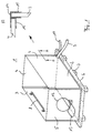
- FIG. 1 a therapy tub designated overall by 1 is shown.
- the actual tub container of the therapy tub 1 is composed of a bottom wall 2, two side walls 3 and a rear end wall 4 and a front end wall 5.
- the tub container is surrounded by a collecting channel 6 and stands on a number of feet 7.
- Inside the tub container is arranged on each side wall 3, a holding rod 8, of which only one in FIG. 1 is visible.
- a hose 9 is attached to the tub container in the area of a lower edge and ends in a sewage pipe (not shown) or in a pump.
- a hose 10 is arranged on the gutter 6.
- the front end wall 5 has a head cutout 12 which is circular in FIG. 1.
- a headrest 13 is provided below the head cutout 12 on the outside of the end wall 5.
- the walls of the therapy tub 1 from FIG. 1 are connected to one another via box profiles 14, which, as shown in section A, are fastened to one another at right angles to one another and each accommodate a wall, here the side wall 3 and the rear face wall 4 along their edges, and in which they are glued in with an adhesive 15.
- box profiles 14 which, as shown in section A, are fastened to one another at right angles to one another and each accommodate a wall, here the side wall 3 and the rear face wall 4 along their edges, and in which they are glued in with an adhesive 15.
- the other wall 3 is provided with a screwed-on hook 17, which is fastened to the nuts 19 located on the opposite side of the disk via wing screws 18.
- the profile 14 carries, on an outer side, which is parallel to the outer side of the side wall 3, a tensioning lever 20 which is supported on the profile 14 via a pivot axis 21.
- a bracket 23 is also pivotally attached, which can engage with its end opposite the pivot point 22 in the hook 17.
- a seal 24 with a circular cross section is arranged parallel to the edge of the side wall 3 to be inserted.
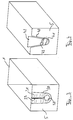
- 3 shows an only stylized therapy tub 1, on the front end face 5 of which an approximately U-shaped, upwardly open head cutout 30 is provided.
- a cuff on the edge 31 attached, which can be closed by means of a waterproof and separable zipper 32 from top to bottom.
- the cuff 31 opens into a tubular cuff area 33 below the zipper 32.
- the head cutout 40 is essentially V-shaped and rounded on its underside. In the area of its curvature, it carries a cuff part 41 on an approximately semicircular piece of its edge. From above, a slide-like insert 42 can be inserted into the head cutout 40 in such a way that an approximately round opening remains in the lower area, the upper one of which is used for the insert 42 associated edge another cuff part 43 is attached, which complements with the cuff part 41 to form a tube-like jacket surrounding the remaining opening all around, but in two parts.
- FIG. 5 shows a therapy tub 1 according to the invention from the side, with a patient 50 located therein, whose head is led out of the tub through a head cutout 12 and rests on a headrest 13.
- the tub stands on feet 7, is open at the top and is provided with an overflow 51 and a drain connection 52.
- the therapy tub 1 can be made of plexiglass, plastic or stainless steel, for example, the material being selected from a hygienic point of view.
- the cuffs 31, 41 and 43 are to be made from a flexible, waterproof and skin-friendly material. In practice, neoprene has proven itself best so far.
- the patient When used as a therapy tub for hydrotherapeutic measures, the patient is placed in the tub, possibly on a low bench, which brings the head to the level of the head cutout 12.
- one of the proposed Cuffs placed around the patient's neck and firmly but comfortably attached to the neck with an elastic band.
- a plasticine-like mass can first be placed around the patient's neck, against which the cuff then seals completely under the tension of the elastic band.
- the cuffs differ as follows:
- the simplest embodiment is a circular hole (for example the head cutout 12 in FIG. 1, to which a tube-like sleeve which is somewhat narrower in the outer diameter to the diameter of the head cutout and in the inner diameter is fastened.
- This type of sleeve has the advantage of being relatively easy to seal and inexpensive be, but it has the disadvantage that the patient must be guided with the head from the inside of the tub through the head opening and thus through the tubular cuff, which is particularly difficult for physically handicapped, for example paralyzed patients.
- the embodiments according to FIGS. 3 and 4 are advantageous.
- the cuff on the zipper 32 is first opened so that the patient can lie down like on a normal couch.
- the head is then in the cutout 33 of the cuff and rests, for example, on a headrest 13 according to FIG. 1 and FIG. 5.
- the waterproof zip fastener 32 is closed from above, for example like a jacket, with the lower area
- opening 33 of the cuff places a collar-like cuff section around the patient's neck, which can then be sealed, for example, with the rubber-elastic band, with a plasticine insert or the like.
- This embodiment has the advantage that in patients with claustrophobic fears the waterproof zipper 32 can be opened from the inside and outside at any time, even when the tub is full, so that the patient can be released from his position immediately.
- a considerable security aspect represents this solution also because in patients with ailing health, the cuff can be opened immediately in the event of a circulatory failure and the patient is thus immediately available for appropriate treatment.
- the water escaping when the cuff is opened does relatively little damage in comparison with the gain in safety in the case of the cuff according to the invention, which can be accepted.
- an approximately V-shaped head cutout 40 is provided on its underside with a semicircular curvature which is smaller in radius than the head cutout 12 according to FIG. the neck being in the area of the lower curve and the head resting on a headrest 13 (see FIG. 1). Then an insert 42 is inserted into the head cutout, which cooperates in a sealing manner with the edges of the head cutout 40 and is used like a plug-in bulkhead, but which has a rounding on the underside which is complementary to the rounding off of the cutout 40, in such a way that overall there is an approximately circular shape Cutout forms.
- the edges of the head cutout 40 and the insert 42 are provided with partial sleeves 41 and 43, which together completely surround the patient's neck and can in turn be sealed against the neck with an elastic band or a plasticine insert or both. Sealing is easier to achieve in this case because the entire cross section of the area covered by the sleeve is smaller than in the case of the head cutout 12 in FIG. 1.
- Hose connections 9 are provided for filling and emptying the therapy tub, which can be connected to the existing water connections, for example in a treatment practice.
- the therapy tub according to the invention can be dismantled for easier transport or even for mobile use.
- the tub then consists essentially of five main elements, namely the wall parts of the bottom wall, side walls and front and rear end walls. In the case of a portable trough, these components are connected to one another via tension levers, as is shown in FIG. 2.
- the respective side walls are inserted into the U-shaped profile 14 fastened to the associated edge of the corresponding end wall, on the profile base of which there is a linear seal 24.
- the hook 17 With the clamping lever 20, the hook 17 is pulled towards the profile via the bracket 23, so that the end edge of the wall 3 presses on the seal 24 and the connection point here becomes watertight.
- the tub is closed with a lid, not shown. Then the tub can be filled with a steam, a gas or a mist, so that the patient's body is completely surrounded by the gas, the mist or the steam and the therapeutically active substances can be absorbed through the skin during the Head, which is sealed from the interior by the cuff, does not come into contact with the active ingredients. For this reason, steam or mist treatments with substances that should not be inhaled or must not come into contact with the mouth or eye mucous membranes are therefore also possible with the therapy tub according to the invention.
- the therapy tub according to the invention offers various therapeutic advantages.
- the patient is in a horizontal position, which in any case is more relaxed for him than the inclined or upright position in a conventional underwater massage tub.
- hydrotherapy treatment possible for the first time thanks to the therapy tub according to the invention.
- the tub With a connected underwater massage pump, the tub is suitable for underwater massages and without a pump, or, when the pump is switched off, for herbal baths or mud baths. If the embodiment with the head sections open at the top is selected, then patients with restricted mobility of the cervical spine, for example due to cervical spine syndrome, are also able to take part in hydrotherapeutic treatments.
- the tub can be dismantled, it can also be used for home care in the home.
Landscapes
- Health & Medical Sciences (AREA)
- Public Health (AREA)
- Epidemiology (AREA)
- Pain & Pain Management (AREA)
- Physical Education & Sports Medicine (AREA)
- Rehabilitation Therapy (AREA)
- Life Sciences & Earth Sciences (AREA)
- Animal Behavior & Ethology (AREA)
- General Health & Medical Sciences (AREA)
- Veterinary Medicine (AREA)
- Devices For Medical Bathing And Washing (AREA)
Priority Applications (2)
| Application Number | Priority Date | Filing Date | Title |
|---|---|---|---|
| EP94105571A EP0682931A1 (fr) | 1994-05-09 | 1994-05-09 | Baignoire thérapeutique |
| DE1995115893 DE19515893A1 (de) | 1994-05-09 | 1995-04-29 | Wanne für therapeutische Behandlungen |
Applications Claiming Priority (1)
| Application Number | Priority Date | Filing Date | Title |
|---|---|---|---|
| EP94105571A EP0682931A1 (fr) | 1994-05-09 | 1994-05-09 | Baignoire thérapeutique |
Publications (1)
| Publication Number | Publication Date |
|---|---|
| EP0682931A1 true EP0682931A1 (fr) | 1995-11-22 |
Family
ID=8215851
Family Applications (1)
| Application Number | Title | Priority Date | Filing Date |
|---|---|---|---|
| EP94105571A Withdrawn EP0682931A1 (fr) | 1994-05-09 | 1994-05-09 | Baignoire thérapeutique |
Country Status (2)
| Country | Link |
|---|---|
| EP (1) | EP0682931A1 (fr) |
| DE (1) | DE19515893A1 (fr) |
Citations (8)
| Publication number | Priority date | Publication date | Assignee | Title |
|---|---|---|---|---|
| GB113318A (en) * | 1917-02-16 | 1918-02-18 | Effie Adela Wharton | An Improved Surgical Limb Bath. |
| GB1171146A (en) * | 1966-12-03 | 1969-11-19 | Manfred Von Ardenne | Partition for a Two-Compartment Bath |
| US3936891A (en) * | 1973-10-11 | 1976-02-10 | Kulde Harry H | Shower spray massage-sauna |
| US4055863A (en) * | 1975-12-22 | 1977-11-01 | Lawrence Edward Duval | Apparatus for bathing persons |
| FR2394289A1 (fr) * | 1977-06-15 | 1979-01-12 | Vervaeke Jean | Dispositif hydrotherapique a fonctions multiples |
| DE3443780A1 (de) * | 1984-11-30 | 1986-06-05 | Georg Bl. 8000 München Schließmann | Verfahren zur hydraulischen und/oder pneumatischen massage und massagegeraet zum durchfuehren des verfahrens |
| EP0194625A2 (fr) * | 1985-03-14 | 1986-09-17 | Emil Grumbach | Cabine de douche et de bain |
| US5228150A (en) * | 1991-12-13 | 1993-07-20 | Parker Milton B | Patient bathing apparatus |
-
1994
- 1994-05-09 EP EP94105571A patent/EP0682931A1/fr not_active Withdrawn
-
1995
- 1995-04-29 DE DE1995115893 patent/DE19515893A1/de not_active Withdrawn
Patent Citations (8)
| Publication number | Priority date | Publication date | Assignee | Title |
|---|---|---|---|---|
| GB113318A (en) * | 1917-02-16 | 1918-02-18 | Effie Adela Wharton | An Improved Surgical Limb Bath. |
| GB1171146A (en) * | 1966-12-03 | 1969-11-19 | Manfred Von Ardenne | Partition for a Two-Compartment Bath |
| US3936891A (en) * | 1973-10-11 | 1976-02-10 | Kulde Harry H | Shower spray massage-sauna |
| US4055863A (en) * | 1975-12-22 | 1977-11-01 | Lawrence Edward Duval | Apparatus for bathing persons |
| FR2394289A1 (fr) * | 1977-06-15 | 1979-01-12 | Vervaeke Jean | Dispositif hydrotherapique a fonctions multiples |
| DE3443780A1 (de) * | 1984-11-30 | 1986-06-05 | Georg Bl. 8000 München Schließmann | Verfahren zur hydraulischen und/oder pneumatischen massage und massagegeraet zum durchfuehren des verfahrens |
| EP0194625A2 (fr) * | 1985-03-14 | 1986-09-17 | Emil Grumbach | Cabine de douche et de bain |
| US5228150A (en) * | 1991-12-13 | 1993-07-20 | Parker Milton B | Patient bathing apparatus |
Also Published As
| Publication number | Publication date |
|---|---|
| DE19515893A1 (de) | 1995-11-16 |
Similar Documents
| Publication | Publication Date | Title |
|---|---|---|
| DE1993626U (de) | Aerztliches geraet fuer die ueberfuehrung, behandlung und unterbringung schwerverletzter. | |
| DE3242642A1 (de) | Vorrichtung zum abstuetzen von tieren | |
| DE19527770C1 (de) | Vorrichtung zur Zugbehandlung der Wirbelsäule und der Gelenke des Menschen | |
| DE2207738A1 (de) | Sitz für eine sanitäre Einrichtung, z.B. einen Nachtstuhl oder ein Wasserklosett | |
| DE2256631B2 (de) | Anordnung für ein hydrotherapeutisches Behandlungsgerät | |
| CH168278A (de) | Gesichtsmaske. | |
| EP0682931A1 (fr) | Baignoire thérapeutique | |
| DE102008050587B4 (de) | Badewanne zur Anwendung für medizinische, therapeutische und körperhygienische Zwecke | |
| EP0008719A1 (fr) | Dispositif pour des traitements, des examens, des tests médicaux ou analogues | |
| DE2431651A1 (de) | Badeeinrichtung, insbesondere fuer bewegungsbehinderte personen | |
| DE3721857A1 (de) | Wasch- und pflegewanne | |
| DE10102783A1 (de) | Badewanne | |
| AT138801B (de) | Vorrichtung zur Vornahme von Darm- und Scheidenspülungen. | |
| DE637022C (de) | Liegevorrichtung mit verstellbarer Rueckenlehne zur Ausfuehrung von Darm- und Scheidenspuelungen | |
| DE2435497C2 (de) | Für Kranke und Behinderte bestimmtes Bett | |
| AT15934U2 (de) | Darmreinigungs-Vorrichtung mit anatomisch geformten abdichtenden Wulst, mit Abflussöffnung, zum Halten eines Schlauches, zum Einbringen einer Flüssigkeit | |
| CH650667A5 (en) | Foot reflex zone water-massaging apparatus | |
| AT118776B (de) | Apparat für subaquale Darmbäder. | |
| CH173542A (de) | Vorrichtung zur Vornahme von Darm- und Scheidenspülungen ausserhalb einer Badewanne. | |
| AT501389B1 (de) | Einrichtung zur behandlung eines menschen | |
| DE102007058129B3 (de) | Massagegerät | |
| WO1987002235A1 (fr) | Cuve de lavage et de soins | |
| DE9420982U1 (de) | Beinstütze als orthopädische Hilfe für Badewannen | |
| DE2435497B1 (de) | Für Kranke und Behinderte bestimmtes Bett | |
| CH580423A5 (en) | Hospital bed for psychiatric patients - has built-in ventilation system, toilet bowl, drain and wash basin |
Legal Events
| Date | Code | Title | Description |
|---|---|---|---|
| PUAI | Public reference made under article 153(3) epc to a published international application that has entered the european phase |
Free format text: ORIGINAL CODE: 0009012 |
|
| AK | Designated contracting states |
Kind code of ref document: A1 Designated state(s): AT CH DE FR GB IT LI NL |
|
| STAA | Information on the status of an ep patent application or granted ep patent |
Free format text: STATUS: THE APPLICATION IS DEEMED TO BE WITHDRAWN |
|
| 18D | Application deemed to be withdrawn |
Effective date: 19960523 |