EP0682956A2 - Tauchanordnung mit Linse und optischer Faser - Google Patents
Tauchanordnung mit Linse und optischer Faser Download PDFInfo
- Publication number
- EP0682956A2 EP0682956A2 EP95108356A EP95108356A EP0682956A2 EP 0682956 A2 EP0682956 A2 EP 0682956A2 EP 95108356 A EP95108356 A EP 95108356A EP 95108356 A EP95108356 A EP 95108356A EP 0682956 A2 EP0682956 A2 EP 0682956A2
- Authority
- EP
- European Patent Office
- Prior art keywords
- lens
- fiber
- optical fiber
- submersible
- ball
- Prior art date
- Legal status (The legal status is an assumption and is not a legal conclusion. Google has not performed a legal analysis and makes no representation as to the accuracy of the status listed.)
- Granted
Links
Images



Classifications
-
- A—HUMAN NECESSITIES
- A61—MEDICAL OR VETERINARY SCIENCE; HYGIENE
- A61B—DIAGNOSIS; SURGERY; IDENTIFICATION
- A61B5/00—Measuring for diagnostic purposes; Identification of persons
- A61B5/0059—Measuring for diagnostic purposes; Identification of persons using light, e.g. diagnosis by transillumination, diascopy, fluorescence
-
- A—HUMAN NECESSITIES
- A61—MEDICAL OR VETERINARY SCIENCE; HYGIENE
- A61N—ELECTROTHERAPY; MAGNETOTHERAPY; RADIATION THERAPY; ULTRASOUND THERAPY
- A61N5/00—Radiation therapy
- A61N5/06—Radiation therapy using light
- A61N5/0601—Apparatus for use inside the body
-
- A—HUMAN NECESSITIES
- A61—MEDICAL OR VETERINARY SCIENCE; HYGIENE
- A61N—ELECTROTHERAPY; MAGNETOTHERAPY; RADIATION THERAPY; ULTRASOUND THERAPY
- A61N5/00—Radiation therapy
- A61N5/06—Radiation therapy using light
- A61N5/0613—Apparatus adapted for a specific treatment
- A61N5/062—Photodynamic therapy, i.e. excitation of an agent
-
- G—PHYSICS
- G02—OPTICS
- G02B—OPTICAL ELEMENTS, SYSTEMS OR APPARATUS
- G02B23/00—Telescopes, e.g. binoculars; Periscopes; Instruments for viewing the inside of hollow bodies; Viewfinders; Optical aiming or sighting devices
- G02B23/16—Housings; Caps; Mountings; Supports, e.g. with counterweight
- G02B23/22—Underwater equipment
-
- G—PHYSICS
- G02—OPTICS
- G02B—OPTICAL ELEMENTS, SYSTEMS OR APPARATUS
- G02B23/00—Telescopes, e.g. binoculars; Periscopes; Instruments for viewing the inside of hollow bodies; Viewfinders; Optical aiming or sighting devices
- G02B23/24—Instruments or systems for viewing the inside of hollow bodies, e.g. fibrescopes
- G02B23/2407—Optical details
- G02B23/2423—Optical details of the distal end
-
- G—PHYSICS
- G02—OPTICS
- G02B—OPTICAL ELEMENTS, SYSTEMS OR APPARATUS
- G02B23/00—Telescopes, e.g. binoculars; Periscopes; Instruments for viewing the inside of hollow bodies; Viewfinders; Optical aiming or sighting devices
- G02B23/24—Instruments or systems for viewing the inside of hollow bodies, e.g. fibrescopes
- G02B23/26—Instruments or systems for viewing the inside of hollow bodies, e.g. fibrescopes using light guides
-
- G—PHYSICS
- G02—OPTICS
- G02B—OPTICAL ELEMENTS, SYSTEMS OR APPARATUS
- G02B6/00—Light guides; Structural details of arrangements comprising light guides and other optical elements, e.g. couplings
- G02B6/24—Coupling light guides
- G02B6/26—Optical coupling means
- G02B6/32—Optical coupling means having lens focusing means positioned between opposed fibre ends
-
- G—PHYSICS
- G02—OPTICS
- G02B—OPTICAL ELEMENTS, SYSTEMS OR APPARATUS
- G02B6/00—Light guides; Structural details of arrangements comprising light guides and other optical elements, e.g. couplings
- G02B6/24—Coupling light guides
- G02B6/42—Coupling light guides with opto-electronic elements
- G02B6/4201—Packages, e.g. shape, construction, internal or external details
- G02B6/4202—Packages, e.g. shape, construction, internal or external details for coupling an active element with fibres without intermediate optical elements, e.g. fibres with plane ends, fibres with shaped ends, bundles
- G02B6/4203—Optical features
-
- A—HUMAN NECESSITIES
- A61—MEDICAL OR VETERINARY SCIENCE; HYGIENE
- A61B—DIAGNOSIS; SURGERY; IDENTIFICATION
- A61B18/00—Surgical instruments, devices or methods for transferring non-mechanical forms of energy to or from the body
- A61B18/18—Surgical instruments, devices or methods for transferring non-mechanical forms of energy to or from the body by applying electromagnetic radiation, e.g. microwaves
- A61B18/20—Surgical instruments, devices or methods for transferring non-mechanical forms of energy to or from the body by applying electromagnetic radiation, e.g. microwaves using laser
- A61B18/22—Surgical instruments, devices or methods for transferring non-mechanical forms of energy to or from the body by applying electromagnetic radiation, e.g. microwaves using laser the beam being directed along or through a flexible conduit, e.g. an optical fibre; Couplings or hand-pieces therefor
- A61B2018/2255—Optical elements at the distal end of probe tips
- A61B2018/2261—Optical elements at the distal end of probe tips with scattering, diffusion or dispersion of light
-
- G—PHYSICS
- G02—OPTICS
- G02B—OPTICAL ELEMENTS, SYSTEMS OR APPARATUS
- G02B6/00—Light guides; Structural details of arrangements comprising light guides and other optical elements, e.g. couplings
- G02B6/24—Coupling light guides
- G02B6/26—Optical coupling means
- G02B6/32—Optical coupling means having lens focusing means positioned between opposed fibre ends
- G02B6/325—Optical coupling means having lens focusing means positioned between opposed fibre ends comprising a transparent member, e.g. window, protective plate
-
- G—PHYSICS
- G02—OPTICS
- G02B—OPTICAL ELEMENTS, SYSTEMS OR APPARATUS
- G02B6/00—Light guides; Structural details of arrangements comprising light guides and other optical elements, e.g. couplings
- G02B6/24—Coupling light guides
- G02B6/36—Mechanical coupling means
- G02B6/3628—Mechanical coupling means for mounting fibres to supporting carriers
- G02B6/3632—Mechanical coupling means for mounting fibres to supporting carriers characterised by the cross-sectional shape of the mechanical coupling means
- G02B6/3644—Mechanical coupling means for mounting fibres to supporting carriers characterised by the cross-sectional shape of the mechanical coupling means the coupling means being through-holes or wall apertures
Definitions
- the present invention relates to a submersible lens fiberoptic assembly for use in a biological environment, and especially to a submersible ball lens fiberoptic assembly for photodynamic therapy treatments (hereinafter referred to as PDT) for transferring radiation from an optical fiber to surrounding tissue.
- PDT photodynamic therapy treatments
- Fig. 1A shows an arrangement known as a cylindrical diffuser.
- a cylindrical optical element 11 is butted against an optical fiber 12, and functions to cylindrically diffuse light coupled into it via the optical fiber.
- Fig. 1B shows a prior an arrangement known as a spherical diffuser.
- a spherical optical element 13 is coupled to an optical fiber 14 by an optical coupling 15, and functions to spherically diffuse light from the optical fiber into surrounding tissue.
- Fig. 1A and 1B One disadvantage of the prior art constructions shown in Fig. 1A and 1B is that every spot light source on the diffusing material emits light in a random direction; that is, there is no localization control over the specific tissue being treated.
- FIG. 3C A third prior art arrangement is shown in Fig. 3C, this being an arrangement known as a submersible microlens.
- a housing 16 encloses a miniature lens 17, and the housing is closed by a transparent cover plate 18.
- the end of an optical fiber 19 is positioned at the back focal point of the lens 17.
- the location of the back focal point of the lens is influenced by the index of refraction of the lens and of the medium in contact with the lens and the optical fiber surface.
- the back focal point is fixed by sealing the fiber and lens in air through use of the housing 16 and window or cover plate 18.
- the ideal assembly for coupling radiation from an optical fiber into tissue is one which produces a highly divergent beam of light whose cross section everywhere, in air or water, is a magnified image of the optical fiber end or face. While the arrangement of Fig. 1C does achieve many of these objections, the construction is complicated and accordingly expensive to manufacture.
- US-A-4 695 697 discloses a submersible lens fiber optic assembly which can produce a highly divergent beam of light for use in a biological environment comprising: an optical fiber with an end face for emitting laser light energy, a fiber jacket means for protecting the optical fiber, a ball lens for producing a controlled and highly divergent beam of light, and a housing means fixed to the fiber jacket means and enclosing the ball lens and the end face of the optical fiber in a predetermined relationship with respect to each other, the lens material being artificial sapphire which usually has a refractive index of 1.76.
- US-A-4 865 029 relates to laser hand-piece with a focusing lens.
- the lens is a GRIN-rod lens which, at a certain length, focuses the laser light within the rod.
- the refractive index of this rod lens is however under 1.7 as described in column 10, line 19 thereof.
- a threaded connection is provided between the lens housing and the fiber jacket, such that the beam divergence can be controlled.
- US-A-4 408 980 discloses a fiber lens assembly comprising a hemispherical lens with its spherical side facing the optical fiber end.
- Zr-material microspheres are per se known from EP-A-0 224 375 (related to the manufacturing of the spheres). The application mentioned in that documents only relates to retroflective pavement markings or traffic sign markings.
- EP-A-0 336 156 discloses a ball lens coupled to a fiber.
- the lens material is not disclosed and the laser beam should be focused outside the lens.
- the lens is a ball lens or a hemisphere lens with its spherical surface facing said optical fiber end, and the fiber jacket and housing is in a threated connection so that the distance between the optical fiber face and the ball lens can be adjusted by simply rotating the housing on the jacket.
- the assembly has good divergent and image formation properties.
- the fiberoptic assembly has a hemisphere lens with its spherical surface facing the optical fiber end for transferring the light beam to areas which are inaccessible to a normal "forward looking" lens, it includes preferably a reflective coating on its plane face.
- a preferred embodiment of the submersible lens fiberoptic assembly of the present invention includes a ball lens 20, an optical fiber 21 having a fiber jacket 22 and a cylindrical housing 23.
- the ball lens 20 is preferably made of zirconia because of its mechanical, thermal and optical properties. Specifically, zirconia is a very hard material. If a zirconia ball is placed on a lab table and struck with a carpenter's hammer, for example, the table top acquires a dent, but there is no visible damage to the ball. This ability to withstand rough handling simplifies the assembly procedure.
- the cylindrical housing 23 can be made of metal, such as brass. One end of the metal housing is drilled to take the press-fitted ball lens 20.
- the metal housing 23 and the fiber jacket 22 are preferably threadedly coupled so that the distance between the optical fiber face and the ball lens can be adjusted precisely by simply rotating the housing 23.
- the pressfit and the tight thread on the fiber jacket make a water tight seal to the air chamber (generally indicated by reference numeral 24) on the input side of the ball. Care must be taken to insure that this volume is free of particles during assembly since the ball lens produces an enlarged image of particles lying on the face of the fiber.
- the exposed surface of the ball lens 20 needs no special protection or cleaning procedure. This was demonstrated in an experiment wherein a ball lens fiberoptic was coupled to an argon pumped dye laser and submerged in a test tube of human blood. The dye laser power was increased until the blood adjacent to the lens surface was boiling vigorously. The ball lens fiberoptic was withdrawn and allowed to "smoke". The baked blood was scraped from the lens surface with a knife edge and the surface was wiped clean with an alcohol soaked gauze. The focused spot using this ball lens appeared to be the same as before the test.
- the ball lens 20 is a 1 mm diameter precision optical sphere made of zirconia, and the metal housing or cylinder 23 is drilled through from the opposite end to take a 120 thread per inch tap. Suitable zirconium spheres are commercially available from Precomp Inc., of Great Neck, New York.
- the metal housing is threaded into the jacket 22 of a 400 micrometer diameter optical fiber until the polished fiber end is in contact with the sphere, and then backed off one-half turn.
- the back focal point for the submerged ball lens assembly is 108 micrometers from the surface of the ball lens. This is a half turn of the thread.
- the back focal point for the lens in air is inaccessible, being 33 micrometers inside the ball. However, the fiber end is nearly focused in air and appears sharp in water, even if the fiber is in contact with the ball.
- Fig. 3 The passage of light through the ball lens in air is demonstrated by the tracing of oblique meridonal rays as shown in Fig. 3 and 4.
- the wavelength is 630 nm, for which the index of refraction of zirconia is 2.152.
- Fig. 3 is drawn on a scale of 100 X and shows the light field 2 cm from the lens.
- the fiber is in contact with the ball in Fig. 3.
- Each point on the fiber surface is assumed to emit light into a cone with an apex angle given by the numerical aperture (N. A.) of the fiber (N. A. is equal to the sine of half the apex angle).
- N. A. is equal to the sine of half the apex angle.
- Nine such points are labled in the figure. Three rays from each point are drawn to show how the ball lens forms a focused image of the fiber end.
- the ray traces are symmetrical about the optical axis (the line through the center of the sphere and perpendicular to the fiber face). All rays from the fiber having a common direction are focused by the input surface at a point inside the ball. Three such focal points are shown in Fig. 3 for the three rays of the cone. This focusing of the rays inside the lens occurs because the lens is spherical, its index of refraction is greater than 2, and the input surface of the sphere is in air. The light beam has its smallest diameter inside the sphere. The rays diverge from the focal points and are refracted at the output surface to form a more (in air) or less (in water) rapidly diverging beam.
- the rays of the output beam near the lens in Fig. 3 are extended in Fig. 4 into the far field.
- the points of origin of the rays are indicated by the numbers on the right of the drawing.
- the rays from any point on the fiber face appear in the output beam as nearly parallel rays and are on the opposite side of the optical axis.
- the three diverging rays from the top of the fiber in Fig. 3 appear in Fig. 4 as three nearly parallel rays at the bottom of the beam.
- any cross section of the beam in the far field of the lens is a magnified, inverted, nearly focused image of the fiber face. Therefore, there is no need for a window on the lens as is the case with the prior art.
- Approximate but useful expressions can be derived from paraxial ray equations for the output beam divergence and the beam diamter at the output surface of the ball lens. These equations show how physical properties of the fiber, ball lens and medium in which the ball lens is submerged determine output beam parameters.
- Fig. 5 is a plot of the measured light distribution across a spot at 4.1 cm from a 1 mm ball lens.
- the ball lens fiber was coupled to a helium-neon laser (633 nm wavelength) whose output was chopped at 1.5 kHz.
- the instrumentation consisted of a model 4010 Laserguide fiberoptic light guide, a photodetector, an amplifier phase locked to the 1.5 kHz signal, and a digital voltmeter.
- the light guide is a spherical diffuser normally used in PDT treatments of the bladder. It produces a spherically symmetric light field from a 1.7 mm diameter sphere of light diffusing material. Used in reverse it collects light from almost all directions.
- Measurements were made every 2 mm across the beam. Each scan was repeated five times. The measured values were averaged and normalized with respect to the center value. The data are plotted in Fig. 5 with ⁇ one sigma error bars. The illumination is 80 % or better of the maximum value over most of the beam cross section. The distribution is not exactly symmetrical because the ball and fiber were not perfectly aligned. The peaks near the center and the edge may be due to multiple reflections.
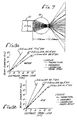
- Smaller diameter balls produce beams of greater divergence as shown in Fig. 6 and 7, relating respectively to 0.89 mm and 0.6 mm ball lens.
- the interior focal points are not as well defined in the 0.6 mm ball lens as in the 1 mm ball lens. This may indicate a fall-off in image quality with increasing curvature of the refractory surface.
- the trace of the horizontal ray emitted from the edge of the fiber is used to define the output beam size.
- the angle which this ray makes with the optical axis after refraction at the output surface is the half-angle beam divergence.
- This ray appears to come from a point on the optical axis close to the output surface of the sphere. Therefore, the beam diameter at the optical axis close to the output surface of the sphere. Therefore, the beam diameter at any distance from the lens is given by twice the product of this distance and the tangent of the half angle divergence.
- Beam diameter plots for 1 mm, 0.8 mm and 0.6 mm ball lenses in water and in air are shown in Fig. 8A and 8B, respectively.
- the full angle of the beam divergence is given next to each curve. These angles are smaller when the ball lens is submerged because water reduces the refraction of rays at the output surface.
- the measured values for the 1 mm ball lens are in agreement with the theoretical prediction.
- the Laserguide Microlens Model 5060 has the same divergence as that predicted for an 800 micron diameter ball lens.
- Fig. 9A, 9B and 9C there is shown another preferred embodiment of the submersible lens fiberoptic system of the present invention which can be used in conjunction with side looking fiberoptic scopes for treatment of areas inaccessible to a "forwarding looking" lens.
- the lens is a hemisphere lens made of zirconia and its spherical surface faces the optical fiber end.
- This type of submersible lens fiberoptic system can produce an output beam at angles up to 120° from the fiber axis. If air is maintained at the plane surface, total internal reflection (TIR) would occur for beam deflection up to 90°. At larger angles a reflective coating would be required.
- Fig. 9A, 9B and 9C show the different arrangements under which the output beams of the system are at angles 60°, 90° and 120° from the fiber axis, respectively.
- Fig. 10 shows an embodiment of the housing 30 used to fix the fiber jacket 22 and lens 20 of the side looking submersible lens fiberoptic assembly.
- the top cover portion is preferably made of plastic material such as epoxy.
- the top cover portion can be formed in the following way. The fiber system and lens with an air cap are first held by an appropriate device and correct alignment of the sphere to the fiber is made.
- the lens is fixed to the fiber system by a waxing fixture and put into a silicon rubber mold for casting epoxy.
- the fiber jacket 22 is unscrewed from the assembly and the wax is removed with ether or hot water to provide an air chamber 24 between the lens and fiber.
- the fiber is cleaned and threaded back to a proper focus for use.
Landscapes
- Physics & Mathematics (AREA)
- Health & Medical Sciences (AREA)
- Life Sciences & Earth Sciences (AREA)
- Biomedical Technology (AREA)
- Engineering & Computer Science (AREA)
- Optics & Photonics (AREA)
- General Physics & Mathematics (AREA)
- Pathology (AREA)
- Public Health (AREA)
- Astronomy & Astrophysics (AREA)
- Veterinary Medicine (AREA)
- Animal Behavior & Ethology (AREA)
- General Health & Medical Sciences (AREA)
- Nuclear Medicine, Radiotherapy & Molecular Imaging (AREA)
- Radiology & Medical Imaging (AREA)
- Biophysics (AREA)
- Surgery (AREA)
- Molecular Biology (AREA)
- Medical Informatics (AREA)
- Heart & Thoracic Surgery (AREA)
- Optical Couplings Of Light Guides (AREA)
- Radiation-Therapy Devices (AREA)
- Optical Fibers, Optical Fiber Cores, And Optical Fiber Bundles (AREA)
Applications Claiming Priority (3)
| Application Number | Priority Date | Filing Date | Title |
|---|---|---|---|
| US46163690A | 1990-01-08 | 1990-01-08 | |
| US461636 | 1990-01-08 | ||
| EP91900535A EP0510007B1 (de) | 1990-01-08 | 1990-11-05 | Tauchanordnung mit linse und optischer faser |
Related Parent Applications (2)
| Application Number | Title | Priority Date | Filing Date |
|---|---|---|---|
| EP91900535A Division EP0510007B1 (de) | 1990-01-08 | 1990-11-05 | Tauchanordnung mit linse und optischer faser |
| EP91900535.5 Division | 1990-11-05 |
Publications (3)
| Publication Number | Publication Date |
|---|---|
| EP0682956A2 true EP0682956A2 (de) | 1995-11-22 |
| EP0682956A3 EP0682956A3 (de) | 1996-07-17 |
| EP0682956B1 EP0682956B1 (de) | 2000-02-02 |
Family
ID=23833355
Family Applications (2)
| Application Number | Title | Priority Date | Filing Date |
|---|---|---|---|
| EP91900535A Expired - Lifetime EP0510007B1 (de) | 1990-01-08 | 1990-11-05 | Tauchanordnung mit linse und optischer faser |
| EP95108356A Expired - Lifetime EP0682956B1 (de) | 1990-01-08 | 1990-11-05 | Tauchanordnung mit Linse und optischer Faser |
Family Applications Before (1)
| Application Number | Title | Priority Date | Filing Date |
|---|---|---|---|
| EP91900535A Expired - Lifetime EP0510007B1 (de) | 1990-01-08 | 1990-11-05 | Tauchanordnung mit linse und optischer faser |
Country Status (7)
| Country | Link |
|---|---|
| US (2) | US5190536A (de) |
| EP (2) | EP0510007B1 (de) |
| JP (1) | JPH10511005A (de) |
| AU (1) | AU6897991A (de) |
| CA (1) | CA2075489C (de) |
| DE (2) | DE69026960T2 (de) |
| WO (1) | WO1991010474A1 (de) |
Cited By (5)
| Publication number | Priority date | Publication date | Assignee | Title |
|---|---|---|---|---|
| WO2000014582A3 (de) * | 1998-09-08 | 2000-06-02 | Heidelberger Druckmasch Ag | Abschlussstück für lichtleitfasern |
| US6624187B1 (en) | 2000-06-12 | 2003-09-23 | Health Research, Inc. | Long wave length absorbing bacteriochlorin alkyl ether analogs |
| GB2427559A (en) * | 2002-05-07 | 2007-01-03 | En Technology Ltd | Cosmetic treatment using an adjustable intense pulsed light device |
| US10048454B2 (en) | 2015-09-04 | 2018-08-14 | Corning Optical Communications LLC | Fiber coupling device for coupling of at least one optical fiber |
| EP2553434B1 (de) * | 2010-03-31 | 2018-12-05 | Ecolab USA Inc. | Fluorometriesensor |
Families Citing this family (64)
| Publication number | Priority date | Publication date | Assignee | Title |
|---|---|---|---|---|
| CA2075489C (en) * | 1990-01-08 | 2002-01-01 | Leroy M. Wood | Submersible lens fiberoptic assembly |
| US5370649A (en) * | 1991-08-16 | 1994-12-06 | Myriadlase, Inc. | Laterally reflecting tip for laser transmitting fiber |
| US5361316A (en) * | 1992-03-05 | 1994-11-01 | Lederle (Japan) Ltd. | Optical fiber laser device for transmitting a pulse laser beam |
| US5363461A (en) * | 1993-07-20 | 1994-11-08 | Bergmann Ernest E | Field installable optical fiber connectors |
| DE69514262T2 (de) | 1994-03-23 | 2001-10-11 | Hamamatsu Photonics K.K., Hamamatsu | Katheter mit Lichtleitfaser |
| US5496309A (en) * | 1994-05-06 | 1996-03-05 | Trimedyne, Inc. | Catheter device utilizing a laser beam laterally directed by a high index prism in a liquid medium |
| DE9409616U1 (de) * | 1994-06-17 | 1994-08-04 | Fa. Carl Zeiss, 89520 Heidenheim | Applikator zur Behandlung eines erhöhten Augeninnendruckes mittels Laserstrahlung |
| US6123715A (en) | 1994-07-08 | 2000-09-26 | Amplatz; Curtis | Method of forming medical devices; intravascular occlusion devices |
| US5591161A (en) * | 1995-10-25 | 1997-01-07 | Plc Medical Systems, Inc. | Angled beam delivery handpiece for laser or other monochromatic light source |
| US5836939A (en) * | 1995-10-25 | 1998-11-17 | Plc Medical Systems, Inc. | Surgical laser handpiece |
| US5833683A (en) * | 1996-01-12 | 1998-11-10 | Surgical Laser Technologies, Inc. | Laterally-emitting laser medical device |
| US5784508A (en) * | 1996-02-09 | 1998-07-21 | Turner; R. Scott | Ball, wide-angle illuminator for eye surgery |
| US5782825A (en) * | 1996-03-07 | 1998-07-21 | Miravant Systems, Inc. | Microlens tip assembly for light delivery catheter |
| US6283955B1 (en) | 1996-05-13 | 2001-09-04 | Edwards Lifesciences Corp. | Laser ablation device |
| US5807383A (en) * | 1996-05-13 | 1998-09-15 | United States Surgical Corporation | Lasing device |
| JP2836583B2 (ja) * | 1996-05-31 | 1998-12-14 | 日本電気株式会社 | 受光素子と光ファイバの光学的結合構造 |
| US5849027A (en) * | 1996-09-04 | 1998-12-15 | Mbg Technologies, Inc. | Photodynamic therapy method and apparatus |
| US6096030A (en) * | 1997-09-23 | 2000-08-01 | Pharmacyclics, Inc. | Light delivery catheter and PDT treatment method |
| US5968033A (en) * | 1997-11-03 | 1999-10-19 | Fuller Research Corporation | Optical delivery system and method for subsurface tissue irradiation |
| EP1051128B1 (de) | 1998-01-30 | 2006-03-15 | St. Jude Medical ATG, Inc. | Medizinischer transplantatverbinder oder stopfen sowie verfahren zu ihrer herstellung |
| US5944738A (en) * | 1998-02-06 | 1999-08-31 | Aga Medical Corporation | Percutaneous catheter directed constricting occlusion device |
| US6205272B1 (en) * | 1998-02-27 | 2001-03-20 | Equitech Int'l Corp. | Fiber optic probe for attenuated total internal reflection spectrophotometry |
| US6135996A (en) * | 1998-04-17 | 2000-10-24 | Baxter International, Inc. | Controlled advancement lasing device |
| GB9816492D0 (en) * | 1998-07-30 | 1998-09-23 | Integrated Syst Tech Ltd | Scattering illumination light source |
| EA003414B1 (ru) * | 1998-10-23 | 2003-04-24 | Майкл Иссачарофф | Устройство для нейро-иммуно-эндокринной регуляции и лечения |
| US6454789B1 (en) * | 1999-01-15 | 2002-09-24 | Light Science Corporation | Patient portable device for photodynamic therapy |
| US6602274B1 (en) * | 1999-01-15 | 2003-08-05 | Light Sciences Corporation | Targeted transcutaneous cancer therapy |
| WO2000041726A2 (en) * | 1999-01-15 | 2000-07-20 | Light Sciences Corporation | Noninvasive vascular therapy |
| US6422718B1 (en) | 1999-11-18 | 2002-07-23 | Integrated Systems Technologies Limited | Non-imaging light source for uniform illumination applications |
| WO2001042770A1 (de) | 1999-12-11 | 2001-06-14 | Qualico Gmbh | Vorrichtung zum erfassen von eigenschaften einer bewegten papierbahn |
| US7897140B2 (en) | 1999-12-23 | 2011-03-01 | Health Research, Inc. | Multi DTPA conjugated tetrapyrollic compounds for phototherapeutic contrast agents |
| US7166719B2 (en) | 2002-06-27 | 2007-01-23 | Health Research, Inc. | Fluorinated photosensitizers related to chlorins and bacteriochlorins for photodynamic therapy |
| US6811562B1 (en) | 2000-07-31 | 2004-11-02 | Epicor, Inc. | Procedures for photodynamic cardiac ablation therapy and devices for those procedures |
| US6501878B2 (en) * | 2000-12-14 | 2002-12-31 | Nortel Networks Limited | Optical fiber termination |
| DE60100984T2 (de) | 2001-01-19 | 2004-08-12 | Optosys Sa | Optische Vorrichtung |
| US7338514B2 (en) * | 2001-06-01 | 2008-03-04 | St. Jude Medical, Cardiology Division, Inc. | Closure devices, related delivery methods and tools, and related methods of use |
| EP1467760A2 (de) * | 2002-01-23 | 2004-10-20 | Light Sciences Corporation | Systeme und verfahren zur photodynamischen therapie |
| DE10214811B4 (de) * | 2002-04-04 | 2009-03-19 | Richard Wolf Gmbh | Wellenleiter zur Aufnahme und/oder Abstrahlung elektromagnetischer Strahlung und Verfahren zur Herstellung eines solchen Wellenleiters |
| US9440046B2 (en) | 2002-04-04 | 2016-09-13 | Angiodynamics, Inc. | Venous insufficiency treatment method |
| US7976564B2 (en) | 2002-05-06 | 2011-07-12 | St. Jude Medical, Cardiology Division, Inc. | PFO closure devices and related methods of use |
| AU2003249742A1 (en) | 2002-07-02 | 2004-01-23 | Health Research, Inc. | Efficient synthesis of pyropheophorbide a and its derivatives |
| WO2008124790A2 (en) | 2002-07-10 | 2008-10-16 | Angiodynamics, Inc. | Device and method for endovascular treatment for causing closure of a blood vessel |
| AU2003254675A1 (en) * | 2002-08-09 | 2004-02-25 | Vadim G. Dobkine | A method and a laser device for treatment of infections |
| US8983257B2 (en) * | 2002-08-28 | 2015-03-17 | Nomir Medical Technologies, Inc. | Therapeutic light delivery apparatus, method, and system |
| US8372112B2 (en) * | 2003-04-11 | 2013-02-12 | St. Jude Medical, Cardiology Division, Inc. | Closure devices, related delivery methods, and related methods of use |
| US20040267306A1 (en) | 2003-04-11 | 2004-12-30 | Velocimed, L.L.C. | Closure devices, related delivery methods, and related methods of use |
| US7057100B2 (en) * | 2003-06-26 | 2006-06-06 | The J.C. Robinson Seed Co. | Inbred corn line W23129 |
| EP1804638B1 (de) * | 2004-09-29 | 2012-12-19 | The General Hospital Corporation | System und verfahren zur abbildung optischer kohärenz |
| US8040496B2 (en) * | 2007-03-16 | 2011-10-18 | Lighthouse Imaging Corporation | System and method for an illumination-quality test |
| US20090027917A1 (en) * | 2007-07-23 | 2009-01-29 | Inventec Corporation | Optical fiber indicator light |
| ES2689302T3 (es) * | 2008-02-13 | 2018-11-13 | Andreas Rose | Dispositivo de suministro de luz que proporciona un patrón radial de emisión de luz |
| EP2105779A3 (de) * | 2008-03-21 | 2009-11-18 | FUJIFILM Corporation | Optisches Beleuchtungssystem für Endoskope und Anordnungsverfahren dafür |
| JP2009276502A (ja) * | 2008-05-14 | 2009-11-26 | Olympus Medical Systems Corp | 内視鏡用照明光学系 |
| JP2012519554A (ja) * | 2009-03-05 | 2012-08-30 | サイノシュア・インコーポレーテッド | 熱的外科手術安全装置および熱的外科手術方法 |
| WO2012114333A1 (en) | 2011-02-24 | 2012-08-30 | Ilan Ben Oren | Hybrid catheter for vascular intervention |
| US8992513B2 (en) | 2011-06-30 | 2015-03-31 | Angiodynamics, Inc | Endovascular plasma treatment device and method of use |
| JP2013160513A (ja) * | 2012-02-01 | 2013-08-19 | Shimadzu Corp | モーショントラッカ装置 |
| US12514456B2 (en) | 2013-01-31 | 2026-01-06 | Eximo Medical Ltd. | System and methods for lesion characterization in blood vessels |
| CN105169571B (zh) * | 2015-09-30 | 2017-08-25 | 西安炬光科技股份有限公司 | 一种接触式激光工作头及其医疗美容设备 |
| US11684420B2 (en) | 2016-05-05 | 2023-06-27 | Eximo Medical Ltd. | Apparatus and methods for resecting and/or ablating an undesired tissue |
| US12376904B1 (en) | 2020-09-08 | 2025-08-05 | Angiodynamics, Inc. | Dynamic laser stabilization and calibration system |
| WO2022190280A1 (ja) * | 2021-03-10 | 2022-09-15 | オリンパス株式会社 | 対物光学系、光学ユニットおよび内視鏡装置 |
| US12038322B2 (en) | 2022-06-21 | 2024-07-16 | Eximo Medical Ltd. | Devices and methods for testing ablation systems |
| EP4667999A1 (de) * | 2024-06-20 | 2025-12-24 | Fisba AG | Optisches system |
Citations (5)
| Publication number | Priority date | Publication date | Assignee | Title |
|---|---|---|---|---|
| US4408980A (en) | 1977-07-21 | 1983-10-11 | Industrie Pirelli S.P.A. | Device for manufacturing closed hollow bodies in elastomeric material |
| EP0224375A2 (de) | 1985-11-22 | 1987-06-03 | Minnesota Mining And Manufacturing Company | Transparante, nicht-glasartige Zirkoniumdioxid-Mikrokugeln |
| US4695697A (en) | 1985-12-13 | 1987-09-22 | Gv Medical, Inc. | Fiber tip monitoring and protection assembly |
| US4865029A (en) | 1986-04-24 | 1989-09-12 | Eye Research Institute Of Retina Foundation | Endophotocoagulation probe |
| EP0336156A1 (de) | 1988-03-31 | 1989-10-11 | Siemens Aktiengesellschaft | Hermetisch dichte Lichtleitfaser-Linsen-Anordnung, insbesondere für optoelektronische Module, und Verfahren zu ihrer Herstellung |
Family Cites Families (15)
| Publication number | Priority date | Publication date | Assignee | Title |
|---|---|---|---|---|
| GB1279464A (en) * | 1968-10-03 | 1972-06-28 | Nippon Selfoc Co Ltd | Production of light conducting glass fibres |
| FR2506245B1 (fr) * | 1981-05-20 | 1985-06-14 | Montaz Mautino Ets | Perfectionnement aux installations de transport par cable |
| US4470407A (en) * | 1982-03-11 | 1984-09-11 | Laserscope, Inc. | Endoscopic device |
| US4649151A (en) * | 1982-09-27 | 1987-03-10 | Health Research, Inc. | Drugs comprising porphyrins |
| US4515444A (en) * | 1983-06-30 | 1985-05-07 | Dyonics, Inc. | Optical system |
| US4608980A (en) * | 1984-04-13 | 1986-09-02 | Osada Electric Co., Ltd. | Laser hand piece |
| US4693244A (en) * | 1984-05-22 | 1987-09-15 | Surgical Laser Technologies, Inc. | Medical and surgical laser probe I |
| JPH0741082B2 (ja) * | 1984-09-14 | 1995-05-10 | オリンパス光学工業株式会社 | レ−ザプロ−ブ |
| US4660925A (en) * | 1985-04-29 | 1987-04-28 | Laser Therapeutics, Inc. | Apparatus for producing a cylindrical pattern of light and method of manufacture |
| US4693556A (en) * | 1985-06-04 | 1987-09-15 | Laser Therapeutics, Inc. | Apparatus for producing a spherical pattern of light and method of manufacture |
| US5041109A (en) * | 1986-10-27 | 1991-08-20 | University Of Florida | Laser apparatus for the recanalization of vessels and the treatment of other cardiac conditions |
| US4860743A (en) * | 1986-10-27 | 1989-08-29 | University Of Florida | Laser method and apparatus for the recanalization of vessels and the treatment of other cardiac conditions |
| DE3924491A1 (de) * | 1989-07-25 | 1991-02-07 | Wolf Gmbh Richard | Laserlichtapplikator |
| CA2075489C (en) * | 1990-01-08 | 2002-01-01 | Leroy M. Wood | Submersible lens fiberoptic assembly |
| US5163935A (en) * | 1991-02-20 | 1992-11-17 | Reliant Laser Corporation | Surgical laser endoscopic focusing guide with an optical fiber link |
-
1990
- 1990-11-05 CA CA002075489A patent/CA2075489C/en not_active Expired - Fee Related
- 1990-11-05 WO PCT/US1990/006472 patent/WO1991010474A1/en not_active Ceased
- 1990-11-05 DE DE69026960T patent/DE69026960T2/de not_active Expired - Fee Related
- 1990-11-05 DE DE69033449T patent/DE69033449T2/de not_active Expired - Fee Related
- 1990-11-05 AU AU68979/91A patent/AU6897991A/en not_active Abandoned
- 1990-11-05 EP EP91900535A patent/EP0510007B1/de not_active Expired - Lifetime
- 1990-11-05 EP EP95108356A patent/EP0682956B1/de not_active Expired - Lifetime
- 1990-11-05 JP JP3501052A patent/JPH10511005A/ja active Pending
-
1992
- 1992-02-19 US US07/839,724 patent/US5190536A/en not_active Expired - Lifetime
- 1992-11-24 US US07/980,980 patent/US5403308A/en not_active Expired - Lifetime
Patent Citations (5)
| Publication number | Priority date | Publication date | Assignee | Title |
|---|---|---|---|---|
| US4408980A (en) | 1977-07-21 | 1983-10-11 | Industrie Pirelli S.P.A. | Device for manufacturing closed hollow bodies in elastomeric material |
| EP0224375A2 (de) | 1985-11-22 | 1987-06-03 | Minnesota Mining And Manufacturing Company | Transparante, nicht-glasartige Zirkoniumdioxid-Mikrokugeln |
| US4695697A (en) | 1985-12-13 | 1987-09-22 | Gv Medical, Inc. | Fiber tip monitoring and protection assembly |
| US4865029A (en) | 1986-04-24 | 1989-09-12 | Eye Research Institute Of Retina Foundation | Endophotocoagulation probe |
| EP0336156A1 (de) | 1988-03-31 | 1989-10-11 | Siemens Aktiengesellschaft | Hermetisch dichte Lichtleitfaser-Linsen-Anordnung, insbesondere für optoelektronische Module, und Verfahren zu ihrer Herstellung |
Cited By (5)
| Publication number | Priority date | Publication date | Assignee | Title |
|---|---|---|---|---|
| WO2000014582A3 (de) * | 1998-09-08 | 2000-06-02 | Heidelberger Druckmasch Ag | Abschlussstück für lichtleitfasern |
| US6624187B1 (en) | 2000-06-12 | 2003-09-23 | Health Research, Inc. | Long wave length absorbing bacteriochlorin alkyl ether analogs |
| GB2427559A (en) * | 2002-05-07 | 2007-01-03 | En Technology Ltd | Cosmetic treatment using an adjustable intense pulsed light device |
| EP2553434B1 (de) * | 2010-03-31 | 2018-12-05 | Ecolab USA Inc. | Fluorometriesensor |
| US10048454B2 (en) | 2015-09-04 | 2018-08-14 | Corning Optical Communications LLC | Fiber coupling device for coupling of at least one optical fiber |
Also Published As
| Publication number | Publication date |
|---|---|
| US5190536A (en) | 1993-03-02 |
| JPH10511005A (ja) | 1998-10-27 |
| DE69033449D1 (de) | 2000-03-09 |
| EP0682956B1 (de) | 2000-02-02 |
| EP0510007B1 (de) | 1996-05-08 |
| DE69033449T2 (de) | 2000-10-12 |
| EP0510007A4 (en) | 1993-03-31 |
| DE69026960D1 (de) | 1996-06-13 |
| AU6897991A (en) | 1991-08-05 |
| DE69026960T2 (de) | 1996-09-05 |
| CA2075489A1 (en) | 1991-07-09 |
| WO1991010474A1 (en) | 1991-07-25 |
| US5403308A (en) | 1995-04-04 |
| CA2075489C (en) | 2002-01-01 |
| EP0510007A1 (de) | 1992-10-28 |
| EP0682956A3 (de) | 1996-07-17 |
Similar Documents
| Publication | Publication Date | Title |
|---|---|---|
| EP0682956B1 (de) | Tauchanordnung mit Linse und optischer Faser | |
| US10993768B2 (en) | Radial emissions from optical fibers | |
| US6829411B2 (en) | Wide angle light diffusing optical fiber tip | |
| US5571099A (en) | Side firing probe | |
| US5495541A (en) | Optical delivery device with high numerical aperture curved waveguide | |
| US6687436B2 (en) | Optical fiber with numerical aperture compression | |
| US6246817B1 (en) | Optical fiber with numerical aperture compression | |
| JP5258613B2 (ja) | ライトガイド及び光源装置並びに内視鏡システム | |
| US4815807A (en) | Collimator lens for optical fiber | |
| JPH04297250A (ja) | 腫瘍の光力学的治療のためのファイバー光学装置 | |
| US5317452A (en) | Aligning and attaching a lens to a source of emitted light using light pressure force | |
| KR101608022B1 (ko) | 광섬유의 손상을 예방하는 광학구조를 갖는 치과용 레이저 핸드피스 | |
| JP2943094B2 (ja) | 光ファイバレーザデバイス | |
| US5319399A (en) | Optical alignment device | |
| Melnik et al. | New modified optical fiber tips for medical applications | |
| Conneely et al. | Generation of side-emitting polymer optical fibres by laser ablation for use in antimicrobial applications | |
| Shalem et al. | Optical properties of silver-halide core/clad IR fibers | |
| Rol et al. | Fiber beam shaping and ophthalmic applications | |
| Darafsheh et al. | Integrated microsphere arrays: light focusing and propagation effects | |
| Melnik et al. | Aspherically modified fiber tips have better focusing effect | |
| Gordon | Nonimaging optical designs for laser fiber optic surgery | |
| SU1714558A1 (ru) | Устройство дл ввода излучени полупроводникового лазера в одномодовое оптическое волокно | |
| Pan et al. | Light distribution from optical fiber diffusers | |
| Hauger et al. | Ray-Tracing Calculations of the Focusing Efficiency of Spherical Fiber Ends | |
| Christensen et al. | Fiber optic laser angioplasty probe with optical steerability |
Legal Events
| Date | Code | Title | Description |
|---|---|---|---|
| PUAI | Public reference made under article 153(3) epc to a published international application that has entered the european phase |
Free format text: ORIGINAL CODE: 0009012 |
|
| 17P | Request for examination filed |
Effective date: 19950601 |
|
| AC | Divisional application: reference to earlier application |
Ref document number: 510007 Country of ref document: EP |
|
| AK | Designated contracting states |
Kind code of ref document: A2 Designated state(s): DE FR GB |
|
| RIN1 | Information on inventor provided before grant (corrected) |
Inventor name: POTTER, WILLIAM R. Inventor name: BOYLE, DONN Inventor name: WOOD, LEROY M. |
|
| PUAL | Search report despatched |
Free format text: ORIGINAL CODE: 0009013 |
|
| AK | Designated contracting states |
Kind code of ref document: A3 Designated state(s): DE FR GB |
|
| GRAG | Despatch of communication of intention to grant |
Free format text: ORIGINAL CODE: EPIDOS AGRA |
|
| 17Q | First examination report despatched |
Effective date: 19990323 |
|
| GRAG | Despatch of communication of intention to grant |
Free format text: ORIGINAL CODE: EPIDOS AGRA |
|
| GRAH | Despatch of communication of intention to grant a patent |
Free format text: ORIGINAL CODE: EPIDOS IGRA |
|
| GRAH | Despatch of communication of intention to grant a patent |
Free format text: ORIGINAL CODE: EPIDOS IGRA |
|
| GRAA | (expected) grant |
Free format text: ORIGINAL CODE: 0009210 |
|
| AC | Divisional application: reference to earlier application |
Ref document number: 510007 Country of ref document: EP |
|
| AK | Designated contracting states |
Kind code of ref document: B1 Designated state(s): DE FR GB |
|
| REF | Corresponds to: |
Ref document number: 69033449 Country of ref document: DE Date of ref document: 20000309 |
|
| ET | Fr: translation filed | ||
| PLBE | No opposition filed within time limit |
Free format text: ORIGINAL CODE: 0009261 |
|
| STAA | Information on the status of an ep patent application or granted ep patent |
Free format text: STATUS: NO OPPOSITION FILED WITHIN TIME LIMIT |
|
| 26N | No opposition filed | ||
| PGFP | Annual fee paid to national office [announced via postgrant information from national office to epo] |
Ref country code: GB Payment date: 20011004 Year of fee payment: 12 |
|
| PGFP | Annual fee paid to national office [announced via postgrant information from national office to epo] |
Ref country code: FR Payment date: 20011105 Year of fee payment: 12 |
|
| PGFP | Annual fee paid to national office [announced via postgrant information from national office to epo] |
Ref country code: DE Payment date: 20011130 Year of fee payment: 12 |
|
| REG | Reference to a national code |
Ref country code: GB Ref legal event code: IF02 |
|
| PG25 | Lapsed in a contracting state [announced via postgrant information from national office to epo] |
Ref country code: GB Free format text: LAPSE BECAUSE OF NON-PAYMENT OF DUE FEES Effective date: 20021105 |
|
| PG25 | Lapsed in a contracting state [announced via postgrant information from national office to epo] |
Ref country code: DE Free format text: LAPSE BECAUSE OF NON-PAYMENT OF DUE FEES Effective date: 20030603 |
|
| GBPC | Gb: european patent ceased through non-payment of renewal fee | ||
| PG25 | Lapsed in a contracting state [announced via postgrant information from national office to epo] |
Ref country code: FR Free format text: LAPSE BECAUSE OF NON-PAYMENT OF DUE FEES Effective date: 20030731 |
|
| REG | Reference to a national code |
Ref country code: FR Ref legal event code: ST |