EP0682996B1 - Verfahren und Vorrichtung in einer Biegepresse - Google Patents
Verfahren und Vorrichtung in einer Biegepresse Download PDFInfo
- Publication number
- EP0682996B1 EP0682996B1 EP95870011A EP95870011A EP0682996B1 EP 0682996 B1 EP0682996 B1 EP 0682996B1 EP 95870011 A EP95870011 A EP 95870011A EP 95870011 A EP95870011 A EP 95870011A EP 0682996 B1 EP0682996 B1 EP 0682996B1
- Authority
- EP
- European Patent Office
- Prior art keywords
- jaw
- bending
- jaw parts
- bending jaws
- width
- Prior art date
- Legal status (The legal status is an assumption and is not a legal conclusion. Google has not performed a legal analysis and makes no representation as to the accuracy of the status listed.)
- Expired - Lifetime
Links
Images









Classifications
-
- B—PERFORMING OPERATIONS; TRANSPORTING
- B21—MECHANICAL METAL-WORKING WITHOUT ESSENTIALLY REMOVING MATERIAL; PUNCHING METAL
- B21D—WORKING OR PROCESSING OF SHEET METAL OR METAL TUBES, RODS OR PROFILES WITHOUT ESSENTIALLY REMOVING MATERIAL; PUNCHING METAL
- B21D5/00—Bending sheet metal along straight lines, e.g. to form simple curves
- B21D5/04—Bending sheet metal along straight lines, e.g. to form simple curves on brakes making use of clamping means on one side of the work
- B21D5/045—With a wiping movement of the bending blade
-
- B—PERFORMING OPERATIONS; TRANSPORTING
- B21—MECHANICAL METAL-WORKING WITHOUT ESSENTIALLY REMOVING MATERIAL; PUNCHING METAL
- B21D—WORKING OR PROCESSING OF SHEET METAL OR METAL TUBES, RODS OR PROFILES WITHOUT ESSENTIALLY REMOVING MATERIAL; PUNCHING METAL
- B21D5/00—Bending sheet metal along straight lines, e.g. to form simple curves
- B21D5/04—Bending sheet metal along straight lines, e.g. to form simple curves on brakes making use of clamping means on one side of the work
Definitions
- the invention relates to an apparatus for adjusting the width of the bending jaws of a bending machine, as indicated in the preamble of claim 1, as well as to a method to be used with such an apparatus.
- the bending jaws comprise two sets of jaw parts, whereby the first set comprises a number of narrow plates corresponding to the shape of the bending jaws, the number of plates in connection with the bending jaws being adjustable, whereby said plates are used for fine adjustment of the width of the bending jaws.
- the second set of jaw parts is provided, forming the unit for coarse adjustment of the width of the bending jaws, whereby each piece of the second set, at its end face, which extends substantially outwards from the bending jaws in the longitudinal direction of the bending jaws, comprises a protruding arrangement intended for making possible the function of the bending jaws at the stage of bending particularly the two last edges of the four edges of the sheet.
- the above-presented method and apparatus are relatively difficult to apply into practice particularly because the edge pieces are usually relatively wide in the longitudinal direction of the bending jaws, whereby for fine adjustment, a relatively large number of plates is needed, from which a certain group must be selected for fine adjustment. Furthermore, this construction is expensive, because it contains numerous specially made edge pieces.
- US-A-4 660 402 discloses an apparatus and method for using it in accordance with the preamble of claims 1 and 18, respectively.
- the present solution provides the advantage that the width of the bending jaws of the bending machine can be adjusted in a quick and reliable manner by using simple functional parts.
- the first set of jaw parts makes up a set for so-called fine adjustment.
- their difference in width is preferably defined to be constant, whereby the interval for adjusting the total width is equal to the difference in width of the jaw parts of the first set.
- the width of the jaw parts of the second set is also elected to be constant, and they are used for so-called coarse adjustment of the total width of the bending jaws.
- the number of jaw parts of the second group is elected first to obtain a so-called coarse measurement range for the total width.
- That jaw part is selected from the first set which is most suitable for obtaining the total width of the bending jaws needed for the bending purpose.
- the method is particularly advantageous, because the jaw parts of the second set are simple plates, and there are only two edge pieces that make up a kind of a third set, the width being a constant to be considered in determining the total width of the bending jaws.
- Figures 1 to 3 illustrate a bending machine for applying the method and apparatus for adjusting the width of the bending jaws of a bending machine according to the invention.
- the bending machine comprises as main parts a frame 1, bending jaws 2a, 2b in the frame 1, of which the lower jaw 2a being stationary in the frame 1 and the upper jaw 2b being movable in the vertical direction for pressing the sheet to be bent between the bending jaws 2a, 2b.
- the invention is applied particularly in connection with the upper jaw 2b.
- the bending machine comprises a movable bending jaw arrangement 3a, 3b in a frame structure 4 articulated in the frame 1 and having a C-form when seen in a cross-section perpendicular to the longitudinal direction of the bending machine, whereby the sheet between the bending jaws 2a, 2b in the frame 1 can be bent both from above and from below either by a lower bending jaw 3a or by an upper bending jaw 3b of the bending jaw arrangement 3 in the gap 5 of the C-formed frame 4.
- the bending machine is also provided with a support table 6 for the sheet to be bent.
- the support table 6 is equipped with a transfer device 7 for moving the sheet to be bent in a linear direction towards and away from the bending jaws 2a, 2b; 3a, 3b.
- FIG. 1 to 3 there is also a transfer system for the sheets to be bent, comprising a frame part 8 provided with a horizontal arm 9.
- a movable gripping device 10 is arranged for gripping a pile of sheets placed on the side of the frame 8, -the uppermost sheet 11 thereof, from above, e.g. by a suction pad arrangement 12 in connection with the gripping device 10.
- the gripping device 10 is arranged to rotate around a vertical axis, whereby it can, when operating on the support table 6, always turn the edge of the sheet 11 to be bent next in alignment with the longitudinal direction of the bending jaws 2a, 2b; 3a, 3b upon the many different stages of bending are being carried out.
- the sheet 11 After the sheet 11 has been bent a pre-determined series of times, it is transferred onto the transfer table 13 and to further processing of the bent sheet.
- Figures 1 to 3 also show a main distribution board with the reference number 14 and a central unit with the reference number 15.
- the operations of the bending machine and the devices connected therewith are automated, whereby the bending operations of the sheet to be bent and the readjustments between the bending operations are carried out on the basis of instructions by the programmed automatics to the actuator.
- the width of the bending jaws must be narrowed particularly in connection with bending the third and fourth edges of a rectangular sheet in order to be able to lift the bending jaw, particularly the upper bending jaw 2b in the frame 1, without being prevented by the first and second edge bending of the sheet.
- the bending jaw used in the method of the invention can be programmed in a way that the jaw part R 1n of the first set is temporarily removed from the connection of the bending jaw to an exchange position where it does not prevent the jaws R 2i of the second set from moving towards each other, whereby the width of the bending jaws is made temporarily narrower than its operational width and it [?] can be removed upwards without being prevented by the first and second edge bendings, and the bent sheet can thus be released to be removed from between the clamp jaws.
- the purpose of this invention is particularly to present a method and an apparatus, whereby upon bending a sheet in several stages, the most critical width of the bending jaws, i.e. the width of the upper, vertically movable bending jaw 2b (the clamp jaw) of the bending machine, can be adjusted by degrees.
- the basic idea of the invention is schematically illustrated particularly in Fig. 4.
- the bending jaw comprises:
- the non-operational points are preferably in connection with the bending machine and form a first storage EV for the jaw parts of the first set R 1 and a second storage TV (TV 1 , TV 2 ) for the jaw parts of the second set R 2 .
- the second storage TV consists of two parts, being placed on both sides of the operational width L of the bending jaws.
- the jaw part R 1n of the first set in the operational position T is placed in the middle of the bending jaws, and the jaw parts R 2i of the second set in the operational position T are placed on both sides of the jaw part R 1n of the first set.
- the width L of the bending jaws is determined by electing a certain jaw part R 1n from the first set.
- the first set R 1 is elected to comprise a group of jaw parts of the first set with different width, intended for fine adjustment of the width of the bending jaws. Only one (R 1n ) of the jaw parts of the first set (R 1 ) is in operational connection with the bending jaws at a time.
- the second set R 2 is elected to comprise a group of plate-likejaw parts with equal width, whereby the jaw parts R 2i of the second set in the operational position are intended for coarse adjustment of the width of the bending jaws.
- the total width L of the bending jaws is formed by a formula which is programmed in the programming logistics of the bending machine according to the dimensions of the quantities affecting the width of the jaw parts R 1 , R 2 and of the edge parts RK 1 , RK 2 etc. and according to the strategy of electing the width of the bending jaws.
- the total width L is elected according to the formula presented above, using the references of Fig. 4.
- the constant C in the equation presented on the width of the bending jaws is substantially composed of four partial constants, which are the widths C R of the edge pieces RK 1 and RK 2 and the widths C L of the locking pieces of the center part KO.
- the coarse adjustment is made by election of the number of jaw parts R 2i of the second set R 2 in the operational position T, whereby the bending width is gradual P for the coarse adjustment, as shown in Fig. 5.
- the difference LE in the widths of successive jaw parts of the first set is constant.
- This width difference constant LE is divided evenly in the range of the coarse adjustment step P so that the minimum deviation MP of the total width L of the bending jaws is the difference LE in the widths of jaw parts of the first set R 1 .
- the minimum deviation is indicated with the reference MP. This gives a series of ascending or descending steps of functional total widths L of the bending jaws, from which the desired total width L can be selected on the basis of the dimensions of the first and second set.
- the width KL 8 of the eighth jaw part R 1,8 of the first set R 1 is 170.
- the constant C M can be included in the constant C of the equation for defining the width of the bending jaws (Formula 1).
- the total width C K of the edge piece RK 1 , RK 2 (Fig. 4), C K > C R ) in the longitudinal direction of the bending jaws is elected to substantially correspond to, or to be smaller than, the joint width LM * N of jaw parts of the jaw part series PL M to be removed from the second set R 2 .
- the method is used, in connection with changing the total width L of the bending jaws, for removing a series of jaw parts of the second set R 2 (jaw part series PL M ) from both ends of the bending jaws and placing the edge pieces RK 1 , RK 2 in the openings thus formed, these being thus preferably wider than the width C K of the edge pieces in the longitudinal direction of the bending jaws.
- the jaw parts of the second set R 2 removed for the previous width adjustment of the bending jaws, are returned to connection with the bending jaws, at the removal point of the edge pieces RK 1 , RK 2 , and/or the jaw parts of the second set R 2 are compressed into a uniform set.
- the exchange of a jaw part of the first set R 1 is shown in two alternative embodiments.
- the jaw parts of the first set R 1 are placed in connection with the first storage EV.
- the jaw part R 1n in the operational position in connection with the bending jaws is exchanged by a transfer device 16 effective between the first storage EV and substantially the location S of the jaw part R 1n .
- the exchange of the jaw part of the first set is shown in steps a to f.
- the partial figure a shows the starting point when the previous bending programme is finished and the next bending programme to be carried out by the bending machine requires the exchange of a jaw part of the first set.
- the first storage EV moves in relation to the frame 1 of the working machine so that the jaw part R 1m of the first set R 1 to be used next comes against the first gripping means 17 of the transfer device 16, which grips said jaw part R 1m .
- the jaw parts of the first set can be placed in a row in connection with the first storage EV, whereby the programming logistics required for the exchange becomes simple.
- the first transfer device 16 comprises a transfer arm 19 which is arranged to be pivotable by actuators (not shown) in the vertical plane in front of the frame 1 around a horizontal shaft 18 fixed in the frame 1, e.g. in a lug 18a, said first gripping means 17 being placed at the free end of the transfer arm 19.
- the locking of the jaw part R 1n of the first set R 1 in the location S is simultaneously released by moving at least those jaw parts R 2i of the second set R 2 which are in the operational position aside in the longitudinal direction of the bending jaws, whereby the locking of the jaw part R 1n is released and it can be lifted in the vertical plane in relation to the frame 1 by a movable support device 22, the jaw part R 1n being fixed thereto, into a first exchange position VA1.
- the transfer arm 19 of the first transfer device 16 revolves into the low position (clockwise in Fig. 7b) in front of the frame 1, i.e. about 180°, the transfer arm 19 pointing substantially downwards.
- the second gripping means 20 in the first transfer device 16 is placed so that it can grip the jaw part R 1n in the first exchange position VA1 in a manner corresponding to that described above in connection with the jaw part R 1m (cf. Fig. 14).
- This step is shown in partial figure 7c.
- the transfer arm 19 is turned e.g. about 10° around the shaft 18 (counterclockwise in Fig.
- the jaw part R 1n is returned to the first storage EV and the jaw parts R 2i of the second set are pressed against the jaw part of the first set R 1m , placed by a downwards movement of the support device 22 from the exchange position VA1 into the location S.
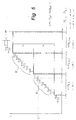
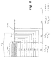
- Fig. 8 shows an alternative way of carrying out the exchange of the jaw part of the first set R 1n ⁇ R 1m .
- the steps presented are substantially similar to those shown in Fig. 7, only with the exception that the jaw parts R 1n ⁇ R 1m are exchanged directly at the location S, without any separate step of moving the jaw part from the location S to the exchange position VA1 and vice versa.
- the location of the exchange position VA1 may correspond to the point to which the jaw part of the first set is moved when narrowing the width in connection with lifting the bending jaws for bringing it away from below the edge bendings.
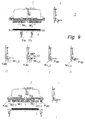
- Fig. 9 shows the exchange of jaw parts of the second set in steps a to 1, as the first embodiment of said exchange.
- Fig. 9a shows the starting point, when the previous bending programme is finished and the next bending programme to be carried out by the bending machine requires the exchange of the operational jaw parts R 2i of the second set with the particular purpose of moving the edge pieces RK 1 , RK 2 to a new position for adjusting the total width.
- the jaw part R 1n of the first set is released from the locking and transferred into the exchange position VA1 (for a possible exchange carried out simultaneously, as shown in Fig. 7) and the jaw parts R 2i of the second set are moved in opposite directions in the longitudinal direction of the bending jaws, whereby they are placed in the exchange position VA1.
- a jaw part series PL M1 at both sides of the bending machine, at both ends of the bending jaws, the width of the series corresponding to or exceeding the width C K of the edge piece (RK 1 , RK 2 ).
- These jaw part series PL M1 are in connection with the second transfer device 30.
- the second storage TV 1 , TV 2 is partly placed in connection with the transfer device 30, whereby the part REI1 of the non-functional ET jaw parts of the second set form extensions to the edge pieces RK 1 , RK 2 at the outer edges of the bending jaws (cf. Fig. 4).
- the second transfer device 30 comprises two transfer units 31a, 31b placed in horizontal conduits 32a, 32b of the bending jaws in the longitudinal direction in the frame 1 of the bending machine, these being placed at both sides of the first transfer device 16 in front of the frame 1 and above the bending jaws.
- the jaw part series PL M1 formed by jaw parts of the second set are both supported by the first gripping means 33 in the transfer units 31a, 31b.
- the transfer units are moved against the edge pieces RK 1 , RK 2 in the horizontal conduits 32a, 32b.
- Fig. 9b the transfer units are moved against the edge pieces RK 1 , RK 2 in the horizontal conduits 32a, 32b.
- the second gripping means 34 of both transfer units 31a, 31b grip the edge pieces RK 1 , RK 2 respectively, whereby particularly in connection with the gripping movement of the gripping means (arrow E1 in Fig. 9c), at least part of the locking of the edge pieces RK 1 , RK 2 is released along the horizontal conduit 37.
- the frame 35 of the transfer unit is moved, supported by the horizontal conduit 37 therein, whose longitudinal direction is perpendicular to the longitudinal direction of the bending jaws, away from the bending jaws (arrow P1 in Fig.
- the transfer unit 31a, 31b moves next the edge piece RK 1 , RK 2 of the jaw part series PL M1 to the previous location (arrow E2 in Fig. 9e).
- the transfer units 31a, 31b are moved along the horizontal conduit 37 away from the bending jaws, supporting the edge piece RK 1 , RK 2 (arrow P2 in Fig. 9f). Further, both transfer units 31a, 31b are moved, as shown in Fig. 9g, to a new location of the edge pieces RK 1 , RK 2 , and the steps shown in Figs.
- 9h-k are carried out, substantially corresponding to the removal of the edge piece RK 1 , RK 2 described above, with the exception of removing now the jaw part series PL M2 , whose width corresponds to at least the width of the edge piece RK 1 , RK 2 , from said position.
- the edge pieces RK 1 , RK 2 can be placed in position, as shown in Fig. 9j, and the transfer units 31a, 31b can be transferred along the horizontal conduits to the ends of the bending jaws.
- the bending programme can be carried out further according to Fig. 91. Consequently, the number of non-operational jaw parts of the second set as extensions of the edge pieces RK 1 , RK 2 is changed REI1 ⁇ REI2 and the number of operational jaw parts of the second set R 2i ⁇ R 2k (Fig. 9a ⁇ Fig. 91).
- the clamping of the bending jaws in its longitudinal direction is carried out by directing the compression to the outermost jaw part of the non-operational jaw parts REI2 of the second set (cf. Fig. 13).
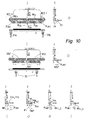
- Fig. 10 shows another embodiment of exchanging the jaw parts R 2i of the second set.
- the transfer units 31a, 31b are empty, the bending jaws carrying out bending.
- All the non-operational jaw parts REI1 of the second set are placed at the side of the edge pieces RK 1 , RK 2 , as extensions of the same.
- the transfer units 31a, 31b in the exchange position VA2 receive the jaw part series PL M1 from the non-operational jaw parts REI1 into the first gripping means.
- the transfer units 31a, 31b are moved against the edge pieces RK 1 , RK 2 , whereby the exchange is carried out as described in connection with Fig. 9 and shown in Figs. 10c-f, the jaw part series PL M1 remaining at the locations of the removed edge pieces RK 1 , RK 2 .
- the edge pieces RK 1 , RK 2 are then placed in a new position as described in connection with Fig. 9 and shown in Figs. 9g-k.
- the transfer units 31a, 31b are moved at the ends of the bending jaws, the jaw part series PL M2 are placed as extensions of the bending jaws, and the bending jaws is clamped.
- the second storage TV 1 , TV 2 is thus the same as the location REI2 of the non-operational jaws parts of the second set.
- This solution gives the advantage that all jaw parts of the second set are clamped in connection with the bending jaws.
- the reference numerals and other markings in Fig. 10 correspond to those in Fig. 9.
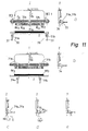
- Fig. 11 shows, in steps a to n, a third embodiment of exchanging the jaw parts of the second set, particularly for use in connection with reducing the operational width.
- the transfer units 31a, 31b are empty at the beginning, and they are moved against the edge pieces RK 1 , RK 2 , respectively; the respective edge pieces are then removed from their previous locations by steps shown in Figs. 11a-e, whereby openings AU are formed.
- the transfer units 31a, 31b are moved in the new locations of the edge pieces RK 1 , RK 2 , respectively (Fig. 11f), and the jaw part series PL M1 at the respective location is gripped and replaced by the edge piece RK 1 , RK 2 by steps shown in Figs. 11g-j.
- Figs. 11k-n said jaw part series PL M1 is moved to the respective end of the bending jaws to form an extension to the operational part of the bending jaws, and the jaw parts are moved towards the center and the bending jaws are clamped in their longitudinal direction, whereby the opening AU formed in the step of Fig. 11f is filled in.
- Fig. 11 is bas ed on the fact that the jaw parts in the operational position T (Fig. 4) are not moved to any particular exchange position (VA1, VA2) according to Figs. 9 and 10 but the longitudinal locking of the bending jaws is released at the beginning (cf. Fig. 13).
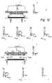
- Fig. 12 shows, in steps a to o, a fourth embodiment of exchanging jaw parts of the second set, particularly in connection with increasing the operational width.
- the basic idea is substantially the same as that shown in Fig. 11, with the exception that at the step shown in Fig. 9f, actuators 49a, 49b (described more closely in connection with Fig. 13) are used for moving the jaw parts of the second set, which at the preceding stage were in the non-operational position in the second storage TV 1 , TV 2 (sets REI1), towards the center part KO for filling in the opening AU left by the edge pieces RK 1 , RK 2 by the steps shown in Figs. 12a-e.
- the steps shown in Figs. 12g-o correspond to those shown in Figs. 11f-n.
- Figs. 11 and 12 are characterized by not carrying out transfers to the exchange positions (VA1 and VA2). This is particularly advantageous when jaw parts of only the second set are exchanged, whereby an exchange of the jaw part of the first set, which is possible simultaneously, is not carried out.
- the locking in the longitudinal direction and the transfers of the jaw parts of the second set are carried out by the actuators 49a and 49b.
- the jaw part R 1n elected from the first set R 1 is arranged to be placed in a central part KO.
- the central part KO consists mainly of two locking pieces 40a, 40b preferably with an L form when seen in the direction perpendicular to the longitudinal axis of the bending jaws. The locking pieces are placed against each other so that the jaw part R 1n selected from the first set is placed between the end faces 42a, 42b of the base parts 41a, 41b of the L forms placed against each other.
- the back surfaces 43a, 43b of the vertical parts 44a, 44b of the L forms extend towards the jaw parts aR 2i , bR 2i of the second set, being supported by said jaw parts and/or the edge pieces RK 1 , RK 2 .
- the bending jaws are supported in relation to the frame 1 of the bending machine against the conduits 45 in the longitudinal direction of the bending jaws.
- the frame part 46a, 46b of the bending jaws consists of two parts.
- each bending jaw part 48a, 48b consists firstly of one locking piece (either 48a or 48b) of the central part KO, secondly of half of the jaw parts of the second set R 2 (i.e. either the combination aR 2i and aREI or bR 2i and bREI), and thirdly of one edge piece (either RK 1 or RK 2 ).
- the actuators 47a, 47b are arranged to carry out a movement in the longitudinal direction of the bending jaws.
- the actuators 47a, 47b can be cylinder-piston-arrangements driven by a pressurized medium, whereby the piston is fixed to the frame part 46a, 46b and the cylinder preferably to the frame 1.
- the length of movement of the actuators 47a, 47b in the longitudinal direction of the bending jaws is elected so that, firstly, the bending jaws can be placed in the exchange position VA2 of the jaw parts of the second set; and secondly, the length of movement is sufficient for clamping the jaw part, particularly the narrowest jaw part, of the first set that is to be placed in connection with the central part KO between the end faces 42a, 42b of the locking pieces and further for bringing the end faces 42a, 42b substantially against each other for the purpose of narrowing the blade width temporarily when removing the bending jaws upwards between the edge bendings of the sheet.
- the exchange position VA2 for jaw parts of the second set is arranged so that the widest jaw part of the first set R 1 can be placed between the end faces 42a, 42b of the locking parts 40a, 40b, the jaw parts of the second set being placed in the exchange position VA2.
- an actuator 22a for moving the jaw part R 1n of the first set in the vertical direction is a cylinder-piston arrangement driven by a pressurized medium, the piston being fixed to the support device 22 and the cylinder to the frame 1.
- the locking parts 40a, 40b of the central part KO are fixed at the top of the vertical parts 44a, 44b to the frame parts 46a, 46b of the bending jaws, respectively, against opposite ends of said frame parts.
- the locking parts 40a, 40b are directed downwards at the ends of the frame parts, from the bottom surface thereof, so that the end surfaces 42a, 42b at the lower part thereof are directed against each other.
- the locking parts 40a, 40b in connection with the central part KO can, as distinct from the L form shown in Fig. 13, also be e.g. rectangular, whereby the vertical end and back surfaces of the same are also substantially equal in size. Also other cross-sectional forms are feasible.
- the bending jaw parts 48a, 48b comprise each an actuator 49a, 49b.
- the purpose of these actuators is to lock the combination, which is in connection with the respective frame part 46a, 46b and comprises firstly the operational jaw parts of the second set (either aR 2i or bR 2i ), secondly one edge piece (either RK 1 or RK 2 ), and thirdly the non-operational jaw parts of the second set (either aREI or bREI) placed outside the edge pieces as extensions of them, by a compressing effect directed by the actuators 49a, 49b between the buffer 50a, 50b of the respective actuator 49a, 49b and the back surfaces 42a, 42b of the locking pieces 40a, 40b.
- both frame parts 46a, 46b of the bending jaws are provided with a conduit 51a, 51b, e.g. a protruding part, arranged on the bottom surface of the respective frame part 46a, 46b in the longitudinal direction of said frame part.
- Both the jaw parts of the second set and the edge pieces are provided with a counterpart, e.g. a grooving, placed in said conduit 51a, 51b.
- lockings are provided, as will be described below in connection with Figs.
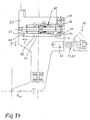
- the jaw part R 1n of the first set is fixed to the support device 22, arranged in the above-described manner to be movable in the vertical direction by the actuator 22a (Fig. 13).
- the jaw part R 1n is provided with a dovetail groove 52 in the longitudinal direction of the bending jaws, and the support device 22 with a dovetail projection 53 in a corresponding manner.
- a locking piece 58 arranged to be movable in relation to the support device 22, the end part of the locking piece 58 forming a first apex 54 of the dovetail projection 53 and the second apex 55 being stationary in relation to the support device 22.
- the oblique apices 54 and 55 are placed in oblique recesses 56, 57 at the edges of the dovetail groove 52.
- the locking piece 58 is articulated with a joint 59 to be pivotable in the vertical plane in connection with the support device 22. Further, the locking piece 58 is connected at its center to a locking actuator 60, whose structure corresponds substantially to that shown in Fig. 15 and to be described further below.
- the locking actuator 60 is placed inside the support device, and it is driven by a pressurized medium.
- the gripping means 17, 20 placed in connection with the first transfer device 16, correspond in their structure to those shown in Figs. 15 and 16, whereby these are provided preferably two means side by side.
- Their counterpart such as a pair of adjacent holes, is placed at a location 61, corresponding in structure to the counterpart 69 shown in Figs. 15 and 16.
- the jaw part R 1n of the first set is released substantially in the same way as shown in Figs. 15 and 16, whereby the first apex 54 is moved by the gripping means 17 (or 20) from the locking position to the point K shown by broken lines, preferably when coupled with the counterpart at the point 61 or by a locking actuator 60 separate from said coupling.
- the jaw part R 1n partly supported by the first transfer device 16, is first moved horizontally to the left in Fig. 14 (arrow I) for releasing the vertical locking between the parts 55 and 57, whereby the first apex, having moved to the point K, does not prevent this movement, and after this downwards in Fig. 14 (arrow II), whereby the jaw part R 1n is released to be moved to the right in Fig.
- the gripping means 17, 20 of the transfer device 16 can be equipped with protruding means or the like, which, upon coupling said gripping means 17, 20 and the jaw- part R 1n (cf. Fig. 16), release the first apex 54 from the groove 56 to the position K.
- Figs. 15 and 16 show-the locking of jaw parts R 2 of the second set and the method of releasing it, primarily the locking and releasing of the jaw part series indicated above with the reference letters PL M , PL M1 and PL M2 as well as of the edge pieces RK 1 , RK 2 , carried out by the second transfer device 30 (transfer units 31a, 31b and the adjacent gripping means 33, 34 in connection with the same).
- conduits 51a, 51b in connection with the frame parts 46a, 46b correspond in their cross-section and general construction to that described in connection with Fig. 14, and the corresponding elements are indicated with reference numerals corresponding to those in Fig. 14.
- the locking piece 58 is substantially a moulding piece of equal length with the frame parts 46a, 46b, equipped with locking actuators 60 at certain intervals in the longitudinal direction of the bending jaws.
- the locking piece 58 is moved by the joint effect of the locking actuators 60 driven by a pressurized medium to the left in Fig. 15, opening the locking between the apex 54 and the recess 56. This takes place after the gripping means 33, 34 has moved to the position shown in Fig. 16, in connection with the jaw part R 2i .
- the gripping means has an interface VP that releases the vertical locking of a rocking arm 62 in the jaw part R 1n , i.e.
- the gripping means 33, 34 is a so-called expanding mandrel 68 with an outer bush 68a with longitudinal grooves, a pin part 68b being arranged to be movable inside the outer bush 68 in its longitudinal direction.
- the jaw part R 2i is provided with a hole 69 functioning as a receiving means.
- the pin part 68b being inside the outer bush 68a in its front position shown in Fig. 16, a friction joint is formed between the outer surface of the radially expanding bush 68a and the inner surface of the hole 69, coupling the jaw part R 2i and the transfer unit 31a, 31b together and coming loose when the pin part 68b is substantially outside the bush 68a.
- the locking actuator 60 comprises a piston rod 70 and a piston 71.
- the piston rod 70 penetrates a sealing part 72 and is coupled with the locking piece 58.
- the frame parts 46a, 46b are provided with longitudinal boreholes 73 and 74 which are connected at opposite sides of the piston 71 for feeding pressurized medium to the cylinder space 75 for moving the piston 71 in the cylinder space 75 and thus for moving the locking piece 58.
- the locking of the locking piece 58 is secured by a pressure spring 76, whereby pressure disturbances do not release the locking between the parts 54 and 56.
Landscapes
- Engineering & Computer Science (AREA)
- Mechanical Engineering (AREA)
- Bending Of Plates, Rods, And Pipes (AREA)
Claims (33)
- Vorrichtung zur Breiteneinstellung der Biegebacken einer Biegepresse, bei der die Biegebacken (2b) im Gestell (1) der Presse zwei Sätze von Backenteilen aufweisen, die zur Breiteneinstellung so angeordnet sind, dass sie mittels Überführungseinrichtungen (16, 30) von einem Arbeitspunkt (T) in einen Ruhepunkt (ET) und/oder umgekehrt führbar sind, welche Punkte mit der Biegepresse verbunden sind, wobeiwobei zum Bestimmen der Breite (L) der Biegebacken der erste und der zweite Satz (R1, R2) auf folgende Weise gebildet werden:der erste Satz (R1) in der Mitte der Biegebacken undder zweite Satz (R2) beiderseits des ersten Satzes angeordnet ist,die Kanten der Biegebacken mit Kantenstücken (RK1, RK2) versehen sind, die Teil der Biegebacken sind und deren Gesamtbreite definieren,wobei die Vorrichtung weiterhin aufweist:der erste Satz (R1) wird zur Bildung einer Gruppe von Backenteilen für die so genannte Feineinstellung ausgewählt,der zweite Satz (R2) wird zur Bildung einer Gruppe von Backenteilen identischer Breite für die so genannte Grobeinstellung ausgewählt, wobei die im Einzelfall jeweils erforderliche Breite der Biegebacken nach der Gleichung
- L =
- Breite der Biegebacken
- R1n =
- Breite des aus dem ersten Satz (R1) gewählten Backenteils (n = 1 .. M),
- N =
- Breite der Backenteile des zweiten Satzes (R2), d.h. eine Konstante,
- R2i =
- Anzahl (i = 0 .., k) der Backenteile des zweiten Satzes (R2) im Arbeitspunkt (T) der Biegebacken, und
- C =
- Konstante, gebildet aus denjenigen Teilen konstanter Breite, die in der Gesamtbreite der Biegebacken enthalten sind,
dadurch gekennzeichnet, dasseinen ersten Speicher (EV) für unbenutzte Backenteile des ersten Satzes (R1),eine erste Überführungseinrichtung (16) zur Übergabe der Backenteile des ersten Satzes (R1) aus dem Speicher EV) in die Arbeitsstellung (T) in den Biegebacken,einen zweiten Speicher (TV) für unbenutzte Backenteile des zweiten Satzes (R2) undeine zweite Überführungseinrichtung (30) zur Übergabe von Kantenstücken (RK1, RK2) und Backenteile des zweiten Satzes (R2) an den durch die Sollbreite der Biegebacken bestimmten Ort und zur Übergabe der unbenutzten Backenteile des zweiten Satzes (R2) an den zweiten Speicher (TV),der erste Satz (R1) ausgewählt wird, um eine Gruppe von Backenteilen unterschiedlicher Breite für die so genannte Feineinstellung zu bilden, die sich jeweils einzeln (R1n) am Arbeitspunkt (T) der Biegebacken befinden, unddie erste Überführungseinrichtung (16) einen Übergabearm (19) oder dergl. aufweist, der mit seinem ersten Ende in der vertikalen Ebene schwenkbar gelagert ist, wobei am zweiten Ende des Übergabearms (19) ein Drehgestell (21) vorgesehen ist, das aufweist:eine erste Greifeinrichtung (17) zum Greifen eines Backenteils (R1m),eine zweite Greifeinrichtung (20) zum Greifen eines anderen Backenteils (R1n) undeine Dreheinrichtung (21a), mit der das Drehgestell (21) gemeinsam mit den Greifeinrichtungen (17, 20) in ihm im wesentlichen um die Längsachse des Übergabearms (19) oder dergl. drehbar ist. - Vorrichtung nach Anspruch 1, dadurch gekennzeichnet, dassder erste Speicher (EV) über den Biegebacken im Gestell (1) der Biegepresse angeordnet ist unddie erste Überführungseinrichtung (16) so angeordnet ist, dass sie in Verbindung mit dem Austausch der Backenteile des ersten Satzes (R1) im wesentlichen in der vertikalen Richtung arbeitet, die relativ zum Gestell (1) der Biegepresse festgelegt ist.
- Vorrichtung nach Anspruch 1 oder 2, dadurch gekennzeichnet, dass der erste Speicher (EV) relativ zum Gestell (1) der Biegepresse bewegbar angeordnet ist, um das auszutauschende Backenteil des ersten Satzes (R1) in die Greifposition der ersten Überführungseinrichtung (16) zu bringen.
- Vorrichtung nach einem der Ansprüche 1 bis 3, dadurch gekennzeichnet, dass der zweite Satz (R2) zur Bildung einer Gruppe von Backenteilen und Kantenstücken (RK1, RK2) ausgewählt wird und dass die Gesamtbreite der Biegebacken sich aus mindestens der Gesamtbreite (CR) der Kantenstücke (RK1, RK2) und der Gesamtbreite (CL) der Sperrteile (LO) zwischen dem ersten und dem zweiten Satz zusammensetzt.
- Vorrichtung nach Anspruch 1, dadurch gekennzeichnet, dassder zweite Speicher (TV) außerhalb der Kantenstücke (RK1, RK2) der Biegebacken in deren Längsrichtung angeordnet ist, um einen zweiteiligen zweiten Speicher (TV1, TV2) zu bilden.
- Vorrichtung nach Anspruch 1 oder 5, dadurch gekennzeichnet, dass der zweite Speicher (TV) mindestens teilweise in Verbindung mit der zweiten Übergabeeinrichtung (30) angeordnet ist.
- Vorrichtung nach Anspruch 1, dadurch gekennzeichnet, dass die zweite Überführungseinrichtung (30) zwei Übergabeeinheiten (31a, 31b) aufweist, die in waagerechten Führungen (32, 32b) im Gestell (1) der Biegepresse vorzugsweise beiderseits der ersten Überführungseinrichtung (16) angeordnet sind, und dass die Übergabeeinheiten (31a, 31b) mit Drehrahmen (36) in Verbindung mit ihrem Rahmen (35) versehen sind, die aufweisen:eine erste Greifeinrichtung (33)eine zweite Greifeinrichtung (34) undeine Dreheinrichtung (36a), mit der der Drehrahmen (36) zusammen mit den Greifeinrichtungen (33, 34) in ihm um eine im wesentlichen vertikale Achse schwenkbar ist.
- Vorrichtung nach Anspruch 1, dadurch gekennzeichnet, dass das aus dem ersten Satz (R1) ausgewählte Backenteil (R1n) in einen Mittelteil (KO) einsetzbar angeordnet ist, das zwei Sperrstücke (40a, 40b) aufweist, die einander so zugewandt sind, dass das aus dem ersten Satz ausgewählte Backenteil (R1n) zwischen die ersten Flächen (42a, 42b) des Sperrstücks (40a, 40b) eingebracht wird, wobei die den Backenteilen des zweiten Satzes (R2) zugewandten zweiten Flächen (43a, 43b) des Sperrstücks (40a, 40b) von den Backenteilen (R2) und/oder den Kantenstücken (RK1, RK2) abgestützt werden.
- Vorrichtung nach Anspruch 1 oder 8, dadurch gekennzeichnet, dass das aus dem ersten Satz (R1) ausgewählte Backenteil (R1n) in einen Mittelteil (KO) einsetzbar angeordnet ist, das zwei Sperrstücke (40a, 40b) aufweist, die rechtwinklig zur Längsrichtung der Biegebacken gesehen im wesentlichen L-förmig oder dergl. sind, wobei die Sperrstücke gegeneinander so gesetzt sind, dass das ausgewählte Backenteil (R1n) des ersten Satzes zwischen den Flächen (42a, 42b) gegenüberliegender kurzer Schenkel (41a, 41 b) der L-Gestalt liegt, wobei die rückseitigen Flächen (43a, 43b) der vertikalen Teile (44a, 44b) der L-Gestalt, die den Backenteilen des zweiten Satzes (R2) zugewandt sind, gegen die Backenteile (R2) und/oder die Kantenstücke (RK1, RK2) abgestützt sind.
- Vorrichtung nach Anspruch 1, 8 oder 9, dadurch gekennzeichnet, dass die Biegebacken gegen das Gestell (1) der Biegepresse von den Führungen (45) abgestützt sind, die in Längsrichtung der Biegebacken angeordnet sind, und dass Stellmotore (47a, 47b) oder dergl. zwischen dem Rahmenteil (46a, 46b) der Biegebacken und dem Gestell (1) der Biegepresse angeordnet sind, um zwei Biegebackenteile (48a, 48b), die jeweilsaufweisen, waagerecht in entgegengesetzten Richtungen zu überführen und so insbesondere das Backenteil des ersten Satzes (R1) freizugeben, um insbesondere das Backenteil des ersten Satzes (R2) auszutauschen und im Arbeitspunkt (T) der Biegebacken in deren Längsrichtung zu versperren und/oder um die Backenteile des zweiten Satzes (R2) nach den Seiten hin - bspw. zur Austauschstellung (VA2) - zu führen.eines der beiden Sperrstücke (40a, 40b) des Mittelteils (KO),mindestens die Hälfte derjenigen Backenteile (aR2i, bR2i) des zweiten Satzes (R2), die sich am Arbeitspunkt (T) befinden, undeines der beiden Kantenstücke (RK1, RK2)
- Vorrichtung nach Anspruch 1 oder 10, dadurch gekennzeichnet, dass jeder Biegebackenteil (48a, 48b) einen Stellmotor (49a, 49b) oder dergl. zum Versperren der Backenteile des zweiten Satzes (R2) zwischen dem Sperrstück (40a, 40b) des Mittelteils (KO) und dem Kantenstück (RK1, RK2), zum Lösen der Versperrung und/oder zum Überführen der Backenteil des zweiten Satzes (R2) in Längsrichtung der Biegebacken aufweist, wobei die Arbeitsrichtung der Stellmotore (49a, 49b) im wesentlichen die Längsrichtung der Biegebacken ist.
- Vorrichtung nach Anspruch 1, 10 oder 11, dadurch gekennzeichnet, dass die Stellmotore (49a, 49b) so angeordnet sind, dass sie auf mindestens einige der Backenteile (aREI, bREI) des zweiten Satzes (R2) in Verbindung mit dem zweiten Speicher (TV) wirken, die Verlängerungen der Kantenstücke (RK1, RK2) bilden.
- Vorrichtung nach Anspruch 1,10,11 oder 12, dadurch gekennzeichnet, dass die Stellmotore (49a, 49b) so angeordnet sind, dass sie zwischen dem Rahmenteil (46a, 46b) der Biegebacken und dem äußersten Backenteil des zweiten Satzes (R2) und/oder dem Kantenstück (RK1, RK2) wirken.
- Vorrichtung nach Anspruch 1 oder 7, dadurch gekennzeichnet, dass die Übergabeeinheiten (31a, 31b) so angeordnet sind, dass sie als Teil des zweiten Speichers (TV) arbeiten, so dass einige der Backenteile der zweiten Gruppe (R2) in eine Ruhestellung (ET) gebracht und dort von der Greifeinrichtung (33 oder 34) abgestützt werden.
- Vorrichtung nach Anspruch 1, 7 oder 14, dadurch gekennzeichnet, dass die Greifeinrichtungen (17, 23; 33, 34) jeweils einen vorstehenden Teil (68) haben, bei dem es sich insbesondere um einen radial aufweitbaren Dom (68) handelt, der in ein Gegenstück (69) wie bspw. eine Bohrung im Backenteil des ersten Satzes (R1), im Backenteil des zweiten Satzes (R2) - vorzugsweise der Backenteilserie (PLM) - und/oder in den Kantenstücken (RK1, RK2) einfahrbar ist.
- Vorrichtung nach einem der Ansprüche 1, 7, 14 oder 15, dadurch gekennzeichnet, dass zwischen dem herausnehmbaren Teil (R1n, R2i, PLM, RK1, RK2) und dem Gestell (1) oder einem Teil desselben - vorzugsweise dem Rahmenteil (46a, 46b) der Biegebacken - eine Sicherheitssperre (62) angeordnet ist, die vorzugsweise beim Ankoppeln der Übergabeeinrichtung (16, 30) durch eine Bewegung derselben lösbar ist.
- Vorrichtung nach einem der Ansprüche 1, 7, 10, 14, 15 oder 16, dadurch gekennzeichnet, dassdie Versperrung der Backenteile des zweiten Satzes (R2) und der Kantenstücke (RK1, RK2) im Rahmenteil (46a, 46b) der Biegebacken zweiteilig angeordnet ist,der Rahmenteil (46a, 46b) mit einer Serie in Längsrichtung der Biegebacken angeordneter, die Versperrung bewirkender Stellmotore (60) versehen ist,die versperrende Stellmotor-Serie (60) mit dem ersten Teil (54, 58) der ersten Versperrung verbunden ist, der im wesentlichen über die Länge des Rahmenteils (46a, 46b) in Längsrichtung der Biegebacken verläuft,der erste Teil (54, 58) der ersten Versperrung rechtwinklig zur Längsrichtung des Rahmenteils (46a, 46b) bewegbar angeordnet ist, um die erste Versperrung (54, 58) zwischen dem Sperrteil (R2i) des zweiten Satzes - insbesondere der Backenteilserie (PLM) - und/oder dem Kantenstück (RK1, RK2) und dem Rahmenteil (46a, 46b) zu lösen, und dassdie zweite Sperre (55, 57) mit einer Folge von Bewegungen relativ zum Gestell (1) der Überführungseinrichtung (16, 30) lösbar angeordnet ist.
- Verfahren zum Einstellen der Breite der Biegebacken einer Biegepresse zur Verwendung mit einer Vorrichtung nach einem der Ansprüche 1 bis 17, bei dem die Biegebacken zwei Sätze von Backenteilen aufweisen, die zum Einstellen der Biegebackenbreite von einem Arbeitspunkt (T) an einen Ruhepunkt (ET) überführt werden und/oder umgekehrt, welche Punkte vorzugsweise in Verbindung mit der Biegepresse stehen, wobeiwobei zum Bestimmen der Breite (L) der Biegebacken der erste und der zweite Satz (R1, R2) auf folgende Weise gebildet werden:der erste Satz (R1) in der Mitte der Biegebacken undder zweite Satz (R2) beiderseits des ersten Satzes angeordnet ist,die Kanten der Biegebacken mit Kantenstücken (RK1, RK2) versehen sind, die Teil der Biegebacken sind und deren Gesamtbreite definieren,dadurch gekennzeichnet, dass der erste Satz (R1) ausgewählt wird, um eine Gruppe von Backenteilen unterschiedlicher Breite jeweils einzeln (R1n) am Arbeitspunkt der Biegebacken zu bilden.der erste Satz (R1) wird zur Bildung einer Gruppe von Backenteilen für die so genannte Feineinstellung ausgewählt;der zweite Satz (R2) wird zur Bildung einer Gruppe von Backenteilen identischer Breite getrennt von den Kantenstücken (RK1, RK2) für die so genannte Grobeinstellung ausgewählt, wobei die im Einzelfall jeweils erforderliche Breite der Biegebacken nach der Gleichung
- L =
- Breite der Biegebacken
- R1n =
- Breite des aus dem ersten Satz (R1) gewählten Backenteils (n = 0 ... M),
- N =
- Breite der Backenteile des zweiten Satzes (R2), d.h. eine Konstante,
- R2i =
- Anzahl (i = 0 ... k) der Backenteile des zweiten Satzes (R2) im Arbeitspunkt (T) der Biegebacken, und
- C =
- Konstante, gebildet aus denjenigen Teilen konstanter Breite, die in der Gesamtbreite der Biegebacken enthalten sind,
- Verfahren nach Anspruch 18, dadurch gekennzeichnet, dass die Anzahl der Backenteile im zweiten Satz (R2) gradzahlig gewählt wird und so viele Backenteile des zweiten Satzes (R2) beiderseits des Backenteils (R1n) aus dem ersten Satz (R1) angeordnet werden, dass man eine symmetrische Biegebackenstruktur erhält, wobei im Term R2i für den Index i = 0, 2, 4, 6 ... k mit k = gradzahlig gilt.
- Verfahren nach Anspruch 18 oder 19, dadurch gekennzeichnet, dass die Anzahl der Backenteile im ersten Satz (R1) auf folgende Weise ausgewählt wird:
- M =
- Anzahl der Backenteile im ersten Satz (R1)
- N oder 2*N =
- Breite jedes Backenteils oder zweier Backenteile im zweiten Satz (R2) und
- LE =
- konstante Breitendifferenz aufeinanderfolender Backenteile (bspw. R1,n und R1,n+1) in einer Folge von Backenteilen des ersten Satzes (R1).
- Verfahren nach einem der Ansprüche 18 bis 20, dadurch gekennzeichnet, dass die Breite der Backenteile des ersten Satzes (R1) wie folgt ausgewählt wird:
- KLn =
- Breite eines bestimmten Backenteils R1,n des ersten Satzes (R1), wobei n = 1 ... M und M =Anzahl der Backenteile ist,
- CM =
- eine Konstante, d.h. die Grundbreite der Backenteile des ersten Satzes,
- K(k) =
- Koeffizient, der in der Formel den Wert 0, 1, 2 bis M-1 annimmt, wobei M gleich der Anzahl der Backenteile ist, und
- LE =
- konstante Differenz der Breite aufeinanderfolgender Backenteile (bspw. R1,n und R1,n+1) in einer Serie von Backenteilen des ersten Satzes (R1),
- Verfahren nach einem der Ansprüche 18 bis 21, dadurch gekennzeichnet, dass in der Biegepresseein erster Speicher (EV) für Backenteile des ersten Satzes (R1) undeine erste Überführungseinrichtung (16) vorgesehen werden, die im wesentlichen zwischen dem ersten Speicher (EV) und dem Ort (S) des Backenteils (R1n) des ersten Satzes (R1) am Arbeitspunkt in den Biegebacken wirkt.
- Verfahren nach einem der Ansprüche 18 bis 22, dadurch gekennzeichnet, dass zum Wechsel des Backenteils (R1n) des ersten Satzes folgende Schritte ausgeführt werden:die Versperrung der Backenteile (R1n) des ersten Satzes am Ort (S) in Längsrichtung wird gelöst;mittels einer Überführungseinrichtung (16) wird das im ersten Speicher (EV) befindliche Backenteil (R1n) des ersten Satzes ergriffen, das als nächstes an den Ort (S) zu bringen ist;die Überführungseinrichtung (16) wird zusammen mit dem an den Ort (S) zu bringenden Backenteil (R1m) des ersten Satzes zu dem herauszunehmenden Backenteil (R1n) des ersten Satzes geführt;mittels der Überführungseinrichtung (16) wird das vom Ort (S) zu entfernende Backenteil (R1n) des ersten Satzes ergriffen und zur Abstützung der Übergabeeinrichtung (16) geführt;mittels der Überführungseinrichtung (16) wird eine Austauschbewegung durchgeführt, bei der die Backenteile (R1n, R1m) so gerichtet werden, dass sie gegeneinander ausgetauscht werden;das am Ort (S) einzusetzende Backenteil (R1m) des ersten Satzes wird an den Ort (S) geführt;das am Ort (S) einzusetzende Backenteil (R1m) des ersten Satzes wird mit den Biegebacken versperrt; unddas herauszunehmende Backenteil (R1n) des ersten Satzes wird mittels der Überführungseinrichtung (16) in den ersten Speicher (EV) eingefügt.
- Verfahren nach einem der Ansprüche 18 bis 23, dadurch gekennzeichnet, dass zum Wechsel des Backenteils (R1n) des ersten Satzes folgende Schritte durchgeführt werden:die Versperrung des Backenteils (R1n) im ersten Satz am Ort (S) in Längsrichtung der Biegebacken wird gelöst;der vom Ort (S) zu entfernende Backteil (R1n) wird an die Austauschposition (VA1) geführt;mittels der Überführungseinrichtung (16) wird das Backenteil (R1n) des ersten Satzes ergriffen, das sich im ersten Speicher (EV) befindet und als nächstes an den Ort (S) gebracht werde soll;die erste Übergabeeinrichtung (16) und der an den Ort (S) zu bringende Backenteil (R1m) des ersten Satzes werden gemeinsam in die Austauschposition (VA1) gebracht;mittels der Übergabeeinrichtung (16) wird das in der Austauschposition (VA1) befindliche und vom Ort (S) zu entfernende Backenteil (R1n) des ersten Satzes ergriffen und auf die Abstützung der Überführungseinrichtung (16) freigegeben;die Austauschbewegung wird von der Überführungseinrichtung (16) ausgeführt, um die Backenteile (R1n, R1m) so zu richten, dass ihre Positionen ausgetauscht werden;das an den Ort (S) zu bringende Backenteil (R1m) des ersten Satzes wird an den Ort (S) geführt und mit dem Biegebacken versperrt;das an den Ort (S) zu bringende Backenteil (R1m) des ersten Satzes wird an den Ort (S) geführt;das Backenteil (R1m) des ersten Satzes wird in Längsrichtung der Biegebacken versperrt; unddas zu entfernende Backenteil (R1n) des ersten Satzes wird von der Überführungseinrichtung (16) an den ersten Speicher (EV) übergeben.
- Verfahren nach einem der Ansprüche 18 bis 24, dadurch gekennzeichnet, dass die Backenteile des zweiten Satzes (R2), die sich jeweils am Arbeitspunkt (T) befinden, auf folgende Weise ausgetauscht werden:die Versperrung mindestens der am Arbeitspunkt (T) befindlichen Backenteile des zweiten Satzes (R2) wird in Längsrichtung der Biegebacken gelöst;die Kantenstücke (RK1, RK2) werden freigegeben und separat von den im Einsatz befindlichen Backenteilen (R2i) des zweiten Satzes mittels einer zweiten Überführungseinrichtung (30) vom Arbeitspunkt (T) in die Austauschposition übergeführt;die zweite Überführungseinrichtung (30) wird an den neuen Ort der Kantenstücke (RK1, RK2) geführt;um einen neuen Einsatzort für die Kantenstücke (RK1, RK2) zu erhalten, wird die Serie (PLM) von Backenteilen des zweiten Satzes (R2) mittels der zweiten Überführungseinrichtung (30) herausgenommen;die Kantenstücke (RK1, RK2) werden an den neuen Einsatzsort der herausgenommenen Serie (PLM) gesetzt; unddie Kantenstücke (RK1, RK2) und mindestens diejenigen Backenteile (R2i) des zweiten Satzes, die sich am Arbeitspunkt (T) befinden, werden in Längsrichtung der Biegebacken versperrt.
- Verfahren nach einem der Ansprüche 18 bis 25, dadurch gekennzeichnet, dass die Backenteile des zweiten Satzes (R2), die sich jeweils am Arbeitspunkt (T) der Biegebacken befinden, wie folgt ausgewechselt werden:mindestens diejenigen Backenteile des zweiten Satzes (R2), die sich am Arbeitspunkt (T) befinden, werden in die Austauschposition (VA2) geführt;die Versperrung mindestens derjenigen Backenteile des zweiten Satzes (R2), die sich am Arbeitspunkt (T) befinden, wird in Längsrichtung gelöst;die Kantenstücke (RK1, RK2) werden freigegeben und unter Benutzung der zweiten Überführungseinrichtung (30) getrennt von den im Einsatz befindlichen Backenteilen des zweiten Satzes (R2i) aus der Arbeits- in die Austauschposition geführt;die Serie (PLM) von Backenteilen des zweiten Satzes (R2) wird an den vorherigen Ort der Kantenstücke (RK1, RK2) gesetzt;die zweite Überführungseinrichtung (30) wird an den neuen Ort der Kantenstücke (RK1, RK2) geführt;um den neuen Einsatzort für die Kantenstücke (RK1, RK2) zu erhalten, wird die Serie (PLM) von Backenteilen des zweiten Satzes (R2) von der zweiten Überführungseinrichtung (30) freigegeben;die Kantenstücke (RK1, RK2) werden an einen neuen Ort, den Ort der herausgenommenen Serie (PLM) gesetzt;die Backenteile des zweiten Satzes werden aus der Austauschposition (VA2) in die Arbeitsposition (T) gebracht und die Kantenstücke (RK1, RK2) und mindestens die im Arbeitspunkt (T) befindlichen Backenteile (R2i) des zweiten Satzes werden in Längsrichtung der Biegebacken versperrt.
- Verfahren nach Anspruch 25 oder 26, dadurch gekennzeichnet, dass für die Dauer zwischen Wechselvorgängen die Serie (PLM) entfernter Backenteile des zweiten Satzes (R2) in Verbindung mit der zweiten Überführungseinrichtung (30) gespeichert wird.
- Verfahren nach Anspruch 25 oder 26, dadurch gekennzeichnet, dass die Serie (PLM) entfernter Backenteile des zweiten Satzes (R2) in Verbindung mit denjenigen Backenteilen des zweiten Satzes (R2) gesetzt wird, die in der Ruhestellung (ET) eine Verlängerung der Kantenstücke (RK1, RK2) bilden.
- Verfahren nach einem der Ansprüche 23 bis 26, dadurch gekennzeichnet, dass die Biegebacken in Längsrichtung durch die zweite Überführungseinrichtung (30) mit zwei Übergabeeinheiten (31 a, 31b) versperrt werden, die an beiden Enden der Backenteile des zweiten Satzes (R2) gesetzt werden.
- Verfahren nach einem der Ansprüche 25 bis 29, dadurch gekennzeichnet, dass die Lücken (AU), die in den Biegebacken durch die Herausnahme der Kantenstücke (RK1, RK2) entstehen, durch Einsetzen der nicht im Einsatz befindlichen Kantenstücke zum Mittelteil (KO) hin gefüllt werden.
- Verfahren nach einem der Ansprüche 25 bis 29, dadurch gekennzeichnet, dass die Gesamtbreite (Ck) der Kantenstücke (RK1, RK2) in Längsrichtung der Biegebacken so gewählt wird, dass sie im wesentlichen gleich dem oder kleiner ist als das Produkt der Breite (N) und der Anzahl (LM) der Backenteile des zweiten Satzes, wobei zwischen der Anzahl (LM) und der Breite (N) der herauszunehmenden Backenteile der Serie (PLk) und der Gesamtbreite (Ck) der Kantenstücke (RK1, RK2) folgender Zusammenhang besteht:
- Verfahren nach einem der Ansprüche 18 bis 31, dadurch gekennzeichnet, dass zum Lösen von Backenteilen des ersten Satzes (R1), Backenteilen des zweiten Satzes (R2) und insbesondere der Backenteilserie (PLM) und/oder der Kantenstücke (RK1, RK2) von den Biegebacken folgende Schritte durchgeführt werden:zum Herstellen der Versperrung werden die Greifeinrichtungen (17, 20; 33, 34) der ersten oder der zweiten Überführungseinrichtung (16, 30) in Verbindung mit dem Gegenstück (69) des jeweils auszutauschenden Teils (R1n, R2i, PLM, RK1, RK2) in den Biegebacken gebracht;falls erforderlich, wird die Sicherheitssperre (62) jedes auszutauschenden Teils (R1n, R2i, PLM, RK1, RK2) gelöst, und zwar insbesondere in Verbindung mit der Übergabebewegung der Greifeinrichtungen (17, 20; 33, 34);die erste Versperrung (54, 55) wird mittels eines Sperr-Stellmotors (60) in Verbindung mit dem Gestell (1) oder einem mit diesem verbundenen Teil (22, 46a, 46b) gelöst;die zweite Versperrung (55, 57) wird mittels einer Serie von Bewegungen der Überführungseinrichtung (16, 30) relativ zum Gestell (1) gelöst, um jedes Teil (R1n, R2i, PLM, RK1, RK2) auf die Abstützung der ersten oder zweiten Überführungseinrichtung (16, 30) zu bringen; unddie Schritte zum Festlegen der Teile (R1n, R2i, PLM, RK1, RK2) werden in umgekehrter Reihenfolge ausgeführt.
- Verfahren nach einem der Ansprüche 18 bis 32, dadurch gekennzeichnet, dass zur Breiteneinstellung der Biegebacken der Austausch von Backenteilen des ersten Satzes (R1) und des zweiten Satzes (R2) - falls erforderlich - im wesentlichen gleichzeitig erfolgt.
Applications Claiming Priority (2)
| Application Number | Priority Date | Filing Date | Title |
|---|---|---|---|
| FI940613A FI96008C (fi) | 1994-02-10 | 1994-02-10 | Menetelmä ja laitteisto taivutuskoneessa |
| FI940613 | 1994-02-10 |
Publications (3)
| Publication Number | Publication Date |
|---|---|
| EP0682996A2 EP0682996A2 (de) | 1995-11-22 |
| EP0682996A3 EP0682996A3 (de) | 1996-01-31 |
| EP0682996B1 true EP0682996B1 (de) | 2001-12-12 |
Family
ID=8540044
Family Applications (1)
| Application Number | Title | Priority Date | Filing Date |
|---|---|---|---|
| EP95870011A Expired - Lifetime EP0682996B1 (de) | 1994-02-10 | 1995-02-09 | Verfahren und Vorrichtung in einer Biegepresse |
Country Status (6)
| Country | Link |
|---|---|
| US (1) | US5775156A (de) |
| EP (1) | EP0682996B1 (de) |
| JP (1) | JP3591738B2 (de) |
| AT (1) | ATE210518T1 (de) |
| DE (1) | DE69524477T2 (de) |
| FI (1) | FI96008C (de) |
Families Citing this family (10)
| Publication number | Priority date | Publication date | Assignee | Title |
|---|---|---|---|---|
| US5934134A (en) * | 1994-11-14 | 1999-08-10 | Amada Company, Ltd. | Bending press |
| FR2750626B1 (fr) * | 1996-07-05 | 1999-01-29 | Jeandeaud Jean Claude | Dispositif permettant d'adapter la taille d'un serre-flan de machine-outil |
| DE19636463C2 (de) * | 1996-09-07 | 1998-07-02 | Eht Werkzeugmaschinen Gmbh | Blechbearbeitungsmaschine für plattenförmige Werkstücke mit einem in einzelne Segmente unterteilten Niederhalter |
| IT1284918B1 (it) * | 1996-10-03 | 1998-05-28 | Salvagnini Italia Spa | Macchina pannellatrice dotata di un premilamiera avente lunghezza programmabile |
| NL1004266C1 (nl) * | 1996-10-14 | 1998-04-15 | Cornelis Hendricus Liet | Gereedschaphouder voor het uit een aantal delen bestaande klemgereedschap van een zet- of vouwbank of dergelijke, alsmede zet- of vouwbank of dergelijke voorzien van een dergelijke gereedschaphouder. |
| DE19733578C2 (de) * | 1997-08-02 | 2002-10-10 | Dreistern Werk Maschinenbau Gmbh & Co Kg | Biegemaschine zum mehrseitigen Biegen eines plattenförmigen Werkstückes |
| ES2209594B1 (es) * | 2002-01-29 | 2005-06-01 | Goiti, S. Coop. | Maquina paneladora automatica. |
| IT201800020917A1 (it) * | 2018-12-21 | 2020-06-21 | Bystronic Laser Ag | Upper sheet-pressing tools of an industrial machine for the bending of flat metal elements. |
| IT201800020824A1 (it) * | 2018-12-21 | 2020-06-21 | Bystronic Laser Ag | Release device for an industrial machine for the bending of metal elements |
| CN113926882B (zh) * | 2021-10-22 | 2024-07-05 | 新代科技(苏州)有限公司 | 一种折弯中心的换边借位方法 |
Family Cites Families (15)
| Publication number | Priority date | Publication date | Assignee | Title |
|---|---|---|---|---|
| JPS58148021A (ja) * | 1982-02-26 | 1983-09-03 | Hitachi Ltd | 板材折曲げ装置 |
| JPS5816731A (ja) * | 1982-06-09 | 1983-01-31 | Hitachi Ltd | 分割曲げ型付き曲げ装置 |
| JPS5944616U (ja) * | 1982-09-08 | 1984-03-24 | 丸機械工業株式会社 | フオ−ルデイングマシン用金型交換装置 |
| JPS61159224A (ja) * | 1984-12-29 | 1986-07-18 | Maru Kikai Kogyo Kk | プレスブレ−キの型長さ変換装置 |
| US4722214A (en) * | 1985-03-12 | 1988-02-02 | Murata Kikai Kabushiki Kaisha | Split die for holding work during bending operation |
| JPS63119931A (ja) * | 1986-06-30 | 1988-05-24 | Maru Kikai Kogyo Kk | プレスブレ−キの上型交換装置 |
| AT385688B (de) * | 1986-08-14 | 1988-05-10 | Voest Alpine Ag | Vorrichtung zum abkanten von blechzuschnitten |
| AT385689B (de) * | 1986-08-14 | 1988-05-10 | Voest Alpine Ag | Vorrichtung zum abkanten von blechzuschnitten |
| AT385690B (de) * | 1986-08-28 | 1988-05-10 | Voest Alpine Ag | Vorrichtung zum abkanten von blechzuschnitten |
| JP2519751B2 (ja) * | 1986-09-26 | 1996-07-31 | 富士通株式会社 | 車輪周速制御装置 |
| IT1201126B (it) * | 1987-01-09 | 1989-01-27 | Salvagnini Transferica Spa | Macchina piegatrice per la produzione di pannelli in lamiera rettangolari a partire da fogli piani di lamiera |
| JP2521742B2 (ja) * | 1987-02-20 | 1996-08-07 | 株式会社 アマダ | 折曲げ機 |
| EP0392795A3 (de) * | 1989-04-10 | 1991-01-09 | Yamazaki Mazak Kabushiki Kaisha | Werkzeugwechselvorrichtung zur Anwendung bei einer Pressenbremse |
| JPH05212446A (ja) * | 1992-02-07 | 1993-08-24 | Murata Mach Ltd | 板材折曲機の金型交換装置 |
| US5474437A (en) * | 1992-04-24 | 1995-12-12 | Anritsu Corporation | Metallic die device for press machine |
-
1994
- 1994-02-10 FI FI940613A patent/FI96008C/fi active IP Right Grant
-
1995
- 1995-02-09 DE DE69524477T patent/DE69524477T2/de not_active Expired - Fee Related
- 1995-02-09 US US08/386,356 patent/US5775156A/en not_active Expired - Fee Related
- 1995-02-09 AT AT95870011T patent/ATE210518T1/de not_active IP Right Cessation
- 1995-02-09 EP EP95870011A patent/EP0682996B1/de not_active Expired - Lifetime
- 1995-02-10 JP JP02324095A patent/JP3591738B2/ja not_active Expired - Fee Related
Also Published As
| Publication number | Publication date |
|---|---|
| DE69524477D1 (de) | 2002-01-24 |
| EP0682996A2 (de) | 1995-11-22 |
| FI96008B (fi) | 1996-01-15 |
| DE69524477T2 (de) | 2002-07-18 |
| US5775156A (en) | 1998-07-07 |
| JP3591738B2 (ja) | 2004-11-24 |
| ATE210518T1 (de) | 2001-12-15 |
| JPH07251222A (ja) | 1995-10-03 |
| EP0682996A3 (de) | 1996-01-31 |
| FI940613A0 (fi) | 1994-02-10 |
| FI96008C (fi) | 1996-04-25 |
| FI940613A7 (fi) | 1995-08-11 |
Similar Documents
| Publication | Publication Date | Title |
|---|---|---|
| EP0682996B1 (de) | Verfahren und Vorrichtung in einer Biegepresse | |
| US3914974A (en) | Lithographic plate bending arrangement | |
| EP1009636B2 (de) | Druckmaschine mit veränderlichem abstellmechanismus | |
| EP1377453B1 (de) | Druckwerk einer druckmaschine, verfahren zum an- und abstellen eines zylinders sowie verfahren zur herstellung eines druckproduktes | |
| EP0293352A2 (de) | Vorrichtung und Verfahren zum Wechseln einer Folienrolle zur Umhüllung | |
| CA1075575A (en) | Three-point, air-bending sheet metal bender | |
| GB2141958A (en) | Die ejecter device | |
| DE68912981T2 (de) | Verfahren und Vorrichtung zum Aufwickeln einer Bahn. | |
| DE60219267T2 (de) | Greifeinheit für die automatisierte Bearbeitung von Werkstücken, und Vorrichtung und Verfahren mit einer solchen Einheit | |
| CN1112263C (zh) | 一种装有具有规定长度的坯料夹持器的弯折机 | |
| DE4337578A1 (de) | Bogenführende Trommel für Druchmaschinen | |
| DE102019129645A1 (de) | Bogenbearbeitungsmaschine mit zumindest einer Sensoreinrichtung | |
| DE102019133550A1 (de) | Verfahren zur relativen Lageveränderung zumindest eines Transportmittels zumindest eines Zuführsystems einer Bogenbearbeitungsmaschine und Bogenbearbeitungsmaschine | |
| DE10227950A1 (de) | Umschlaganlege- und -anpresseinrichtung | |
| TWI273933B (en) | Automatic control of intermediate pieces in a bending press | |
| CA2067732C (en) | Process for the two-directional bending of sheet metal | |
| EP0719191B1 (de) | Schwenkbiegemaschine | |
| DE102019129650A1 (de) | Verfahren für einen zumindest zeitweisen Transport von Bogen in einer Bogenbearbeitungsmaschine | |
| DE69929062T2 (de) | Dichtung für wärmetauscher und verfahren und vorrichtung zu deren herstellung | |
| EP0418114A2 (de) | Vorrichtung und Verfahren zum Biegen dünner Bleche | |
| DE102019129649A1 (de) | Verfahren für einen zumindest zeitweisen Transport von Bogen in einer Bogenbearbeitungsmaschine | |
| DE102019129652A1 (de) | Bogenbearbeitungsmaschine und Verfahren zur Ausrichtung von Bogen in zumindest einem Anlageaggregat einer Bogenbearbeitungsmaschine | |
| DE29821652U1 (de) | Wechseleinrichtung für Walzen und Zylinder in einer Druckmaschine | |
| EP0891823A3 (de) | Greiferglied für eine Stanze oder eine Matrize einer Stanzvorrichtung | |
| EP0698429A1 (de) | Vorrichtung zum Biegen in einem Arbeitsgang von einer Reihe von parallelen Stangen einer Baustahlmatte |
Legal Events
| Date | Code | Title | Description |
|---|---|---|---|
| PUAI | Public reference made under article 153(3) epc to a published international application that has entered the european phase |
Free format text: ORIGINAL CODE: 0009012 |
|
| AK | Designated contracting states |
Kind code of ref document: A2 Designated state(s): AT DE FR GB IT SE |
|
| PUAL | Search report despatched |
Free format text: ORIGINAL CODE: 0009013 |
|
| AK | Designated contracting states |
Kind code of ref document: A3 Designated state(s): AT DE FR GB IT SE |
|
| 17P | Request for examination filed |
Effective date: 19960724 |
|
| ET | Fr: translation filed | ||
| 17Q | First examination report despatched |
Effective date: 20000803 |
|
| GRAG | Despatch of communication of intention to grant |
Free format text: ORIGINAL CODE: EPIDOS AGRA |
|
| GRAG | Despatch of communication of intention to grant |
Free format text: ORIGINAL CODE: EPIDOS AGRA |
|
| GRAH | Despatch of communication of intention to grant a patent |
Free format text: ORIGINAL CODE: EPIDOS IGRA |
|
| GRAH | Despatch of communication of intention to grant a patent |
Free format text: ORIGINAL CODE: EPIDOS IGRA |
|
| GRAA | (expected) grant |
Free format text: ORIGINAL CODE: 0009210 |
|
| RAP1 | Party data changed (applicant data changed or rights of an application transferred) |
Owner name: LILLBACKA JETAIR OY |
|
| AK | Designated contracting states |
Kind code of ref document: B1 Designated state(s): AT DE FR GB IT SE |
|
| REF | Corresponds to: |
Ref document number: 210518 Country of ref document: AT Date of ref document: 20011215 Kind code of ref document: T |
|
| REG | Reference to a national code |
Ref country code: GB Ref legal event code: IF02 |
|
| RAP2 | Party data changed (patent owner data changed or rights of a patent transferred) |
Owner name: LILLBACKA JETAIR OY |
|
| REF | Corresponds to: |
Ref document number: 69524477 Country of ref document: DE Date of ref document: 20020124 |
|
| ET | Fr: translation filed | ||
| PLBE | No opposition filed within time limit |
Free format text: ORIGINAL CODE: 0009261 |
|
| STAA | Information on the status of an ep patent application or granted ep patent |
Free format text: STATUS: NO OPPOSITION FILED WITHIN TIME LIMIT |
|
| 26N | No opposition filed | ||
| PGFP | Annual fee paid to national office [announced via postgrant information from national office to epo] |
Ref country code: SE Payment date: 20080213 Year of fee payment: 14 Ref country code: IT Payment date: 20080228 Year of fee payment: 14 Ref country code: GB Payment date: 20080205 Year of fee payment: 14 |
|
| PGFP | Annual fee paid to national office [announced via postgrant information from national office to epo] |
Ref country code: AT Payment date: 20080218 Year of fee payment: 14 |
|
| PGFP | Annual fee paid to national office [announced via postgrant information from national office to epo] |
Ref country code: FR Payment date: 20080206 Year of fee payment: 14 Ref country code: DE Payment date: 20080305 Year of fee payment: 14 |
|
| EUG | Se: european patent has lapsed | ||
| GBPC | Gb: european patent ceased through non-payment of renewal fee |
Effective date: 20090209 |
|
| PG25 | Lapsed in a contracting state [announced via postgrant information from national office to epo] |
Ref country code: AT Free format text: LAPSE BECAUSE OF NON-PAYMENT OF DUE FEES Effective date: 20090209 |
|
| REG | Reference to a national code |
Ref country code: FR Ref legal event code: ST Effective date: 20091030 |
|
| PG25 | Lapsed in a contracting state [announced via postgrant information from national office to epo] |
Ref country code: DE Free format text: LAPSE BECAUSE OF NON-PAYMENT OF DUE FEES Effective date: 20090901 |
|
| PG25 | Lapsed in a contracting state [announced via postgrant information from national office to epo] |
Ref country code: GB Free format text: LAPSE BECAUSE OF NON-PAYMENT OF DUE FEES Effective date: 20090209 Ref country code: FR Free format text: LAPSE BECAUSE OF NON-PAYMENT OF DUE FEES Effective date: 20090302 |
|
| PG25 | Lapsed in a contracting state [announced via postgrant information from national office to epo] |
Ref country code: IT Free format text: LAPSE BECAUSE OF NON-PAYMENT OF DUE FEES Effective date: 20090209 |
|
| PG25 | Lapsed in a contracting state [announced via postgrant information from national office to epo] |
Ref country code: SE Free format text: LAPSE BECAUSE OF NON-PAYMENT OF DUE FEES Effective date: 20090210 |