EP0683012A1 - Laminoir à métaux muni d'ensembles opposés d'unités à machines pour l'usinage d'une pièce centrée et procédé de laminage des gorges circulaires d'une pièce - Google Patents
Laminoir à métaux muni d'ensembles opposés d'unités à machines pour l'usinage d'une pièce centrée et procédé de laminage des gorges circulaires d'une pièce Download PDFInfo
- Publication number
- EP0683012A1 EP0683012A1 EP95100046A EP95100046A EP0683012A1 EP 0683012 A1 EP0683012 A1 EP 0683012A1 EP 95100046 A EP95100046 A EP 95100046A EP 95100046 A EP95100046 A EP 95100046A EP 0683012 A1 EP0683012 A1 EP 0683012A1
- Authority
- EP
- European Patent Office
- Prior art keywords
- crankshaft
- fillets
- rolling
- rotation
- axis
- Prior art date
- Legal status (The legal status is an assumption and is not a legal conclusion. Google has not performed a legal analysis and makes no representation as to the accuracy of the status listed.)
- Granted
Links
Images




Classifications
-
- B—PERFORMING OPERATIONS; TRANSPORTING
- B21—MECHANICAL METAL-WORKING WITHOUT ESSENTIALLY REMOVING MATERIAL; PUNCHING METAL
- B21H—MAKING PARTICULAR METAL OBJECTS BY ROLLING, e.g. SCREWS, WHEELS, RINGS, BARRELS, BALLS
- B21H7/00—Making articles not provided for in the preceding groups, e.g. agricultural tools, dinner forks, knives, spoons
- B21H7/18—Making articles not provided for in the preceding groups, e.g. agricultural tools, dinner forks, knives, spoons grooved pins; Rolling grooves, e.g. oil grooves, in articles
- B21H7/182—Rolling annular grooves
- B21H7/185—Filet rolling, e.g. of crankshafts
-
- B—PERFORMING OPERATIONS; TRANSPORTING
- B24—GRINDING; POLISHING
- B24B—MACHINES, DEVICES, OR PROCESSES FOR GRINDING OR POLISHING; DRESSING OR CONDITIONING OF ABRADING SURFACES; FEEDING OF GRINDING, POLISHING, OR LAPPING AGENTS
- B24B39/00—Burnishing machines or devices, i.e. requiring pressure members for compacting the surface zone; Accessories therefor
- B24B39/04—Burnishing machines or devices, i.e. requiring pressure members for compacting the surface zone; Accessories therefor designed for working external surfaces of revolution
-
- B—PERFORMING OPERATIONS; TRANSPORTING
- B24—GRINDING; POLISHING
- B24B—MACHINES, DEVICES, OR PROCESSES FOR GRINDING OR POLISHING; DRESSING OR CONDITIONING OF ABRADING SURFACES; FEEDING OF GRINDING, POLISHING, OR LAPPING AGENTS
- B24B5/00—Machines or devices designed for grinding surfaces of revolution on work, including those which also grind adjacent plane surfaces; Accessories therefor
- B24B5/36—Single-purpose machines or devices
- B24B5/42—Single-purpose machines or devices for grinding crankshafts or crankpins
Definitions
- This invention relates to metal working, more specifically to a new and improved machine for rolling fillets of metallic workpieces and to a new and improved method for simultaneously rolling all or a number of fillets of a workpiece such as e.g. the fillets of crank pins of an engine crankshaft.
- crank pins and main bearings for downsized crankshafts, as well as crankshafts for larger engines have been strengthened by various fillet rolling machines and processes.
- U.S. Patent 5,138,859 to Winkens published August 18, 1992, for a Method and apparatus for multi-stroke crankshaft rolling and deep rolling "discloses a machine unit and method for rolling crankshaft journal grooves to solve the problems that preclude the simultaneous rolling of adjacent crankpins with the available equipment.
- the machine unit and the crankshaft a first relative position to each other, so that the Fillets of a first set of non-adjacent tenons can be rolled.
- the fillets of a second set of non-adjacent pins are then rolled in a second relative position of the machine unit and the crankshaft. With such a construction and method, all fillets are rolled in two stages or two process steps by a single machine.
- the present invention relates to a machine, tool and method similar to that disclosed in copending application No. 176,792, but further enhancing this technique by providing new and improved methods, rolling equipment and tools that are suitable for a wide range of applications are suitable, in particular those in which simultaneous rolling of the fillets from opposite sides of the workpiece or the crankshaft is necessary or desired.
- the present invention solves the space problems encountered in many facilities in which shuttle tools are required to roll the closely spaced or adjacent fillets, which complicates the use of bulky, side-by-side rolling equipment or even excludes.
- a preferred embodiment of the machine of this invention has opposed rows of fillet roller claw units capable of simultaneously deep rolling all fillets of a crankpin seat including the adjacent crank seats and also the main bearing seats of a crankshaft.
- the opposing rows of fillet roller claw units can be moved toward and away from each other simultaneously between (1) an open position in which unfinished workpieces such as e.g. Crankshafts can be loaded into the lathe or finished workpieces can be unloaded from the lathe, and (2) a closed position in which the fillet rolling tools engage in all or a number of the crankpin fillets including the fillets of adjacent crankpins and also in the main bearings that they can be rolled and solidified at the same time.
- unfinished workpieces such as e.g. Crankshafts
- the fillet rolling tools engage in all or a number of the crankpin fillets including the fillets of adjacent crankpins and also in the main bearings that they can be rolled and solidified at the same time.
- This invention further relates to methods of simultaneously rolling fillets of workpieces such as e.g. Crank seats of an elongated internal combustion engine crankshaft, comprising the steps of: (a) inserting one end of the crankshaft into the vice of a power lathe and the other end into a bracket of the machine so that the crankshaft can be driven by the machine about its axis of rotation, (b ) Arranging the left and right side rows of the fillet roller on the left and right side of the axis of rotation, respectively, so that the claw arms of the device extend substantially transversely to the axis and make it possible to load an unprocessed crankshaft into the lathe, (c) moving the left and right side rows of the device from an initial position spaced from the crankshaft to a position where the fillet rolling tool held on the claw arms contacts the fillets of the pin seats, (d) applying a load to the pin seats by the claw arms and the tool, (e) driving the lathe e to rotate the cranks
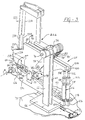
- FIG. 1 depicts part of a machine 10 for rolling the fillets of the seats of a workpiece, which are shown here as angularly offset and adjacent crank pins 12, 14 of an elongated crankshaft 16 of an internal combustion engine.
- the crankshaft 16 is mounted in a workpiece rotating lathe 17 or other mechanism with the front end or flange end 18 of the crankshaft mounted in the chuck of the driving stick 20 and the opposite end on a centering mandrel 24 of the lathe tailstock.
- the drive stick is selectively rotated by a motor 30 so that the crankshaft 16 rotates about its axis of rotation 32.
- the fillet rolling machine 10 has left and right side rows 36, 38, each of which has a plurality of oscillating claw units 40, 42.
- Each oscillating claw unit consists of upper and lower claw arms 44, 46 (left side row of the claw units 40) and 48, 50 (right side row of the claw units 42) which are rotatably connected between the inner and outer ends thereof by pivot pins 52, 54.
- the outer ends of each pair of arms are operatively connected by individually extendable and contractible pneumatic or hydraulic drive cylinders 56, 58 or other suitable control actuators which apply compressive force to the fillet machining rolls for rolling the fillet of the crank pin upon expansion.
- Each drive cylinder has a piston with a connecting rod 60 or 62 which is rotatably connected to a lower arm, while the corresponding cylinder tube projects into a fork shoe 64 or 66 which is rotatably connected to a corresponding upper claw arm 44 or 48.
- each claw unit face each other directly and are angularly offset with upper and lower tools 68, 70 or 72, 74 ( Figure 2) for deep rolling annular grooves 86, 88 and 90, 92 and adjacent crank pins 12, 14 of the crankshaft 16, which are separated by annular webs 94, 96.
- the lower tools 70, 74 are secured to the lower arms of the left and right claw units and have pairs of spaced support rollers 98, 100 which engage and support the pin seats while their fillets are being rolled.
- Such lower support tools are disclosed in more detail in copending U.S. Application No. 176,792, referred to above.
- Each left side 36 claw unit 40 and each right side claw unit 42 is supported by a respective upper swing arm 104, 106 rotatably mounted on the left and right sides of movable upper frames 108, 110 and suspended therefrom, the frames 108, 110 are mounted on a rectilinear slide mechanism or on carriages 112, 114 ( Figures 5 and 6) running along front and rear horizontal support rails 116, 118.
- the rails 116 are in turn fastened on a support beam 120 which is held by stands 122 which are fastened on the floor or a base plate 124.
- Actuators such as hydraulic drive cylinders 126, 128 are operatively connected to the left and right frames 108 and 110 and can be individually driven to move the frames and the associated rows of oscillating claw units operatively connected thereto between a retracted position ( Figure 5 ) for loading and unloading the workpieces and a closed position ( Figures 6 and 7) for the deep groove rolling process.
- a retracted position Figure 5
- a closed position Figures 6 and 7
- the drive motor 30 is connected to the chuck of the drive stick 20 and can optionally be actuated for rotatingly driving the crankshaft 16 about its axis 32.
- the pairs of clamp claws are pivotally attached to swing arms 104, 106 which are rotatably attached to the upper support structure provided by frames 108, 110. If the engine rotates the crankshaft for the deep rolling process, oscillate the arms on an arcuate path and the separate pairs of claws follow the circumference of the radially offset crank pin rotation axis 32 to machine and roll the fillets of these crank pins.
- the rolling pressure is built up by the expansion force of the cylinders 56, 58.
- deep rolling of circular fillets works on the metallic structure of the fillets to secure the fillets and the crankshaft.
- Each of the upper tools 68 and 72 carried by upper arms 44, 46 on the left and right sides of the claw units includes a housing which is releasably secured to the upper claw of each arm by fastening units 48, 150.
- Each housing has a support roller 152, 154 which is seated on needle bearings which are held on centrally aligned hubs 156, 158 arranged between the housing side plates.
- the hardened fillet rollers e.g. rollers 138, 140 are for rotation about mutually inclined axes A, A 'on the lower sides of the tools by cages such as e.g. Cages 160 and opposing adjustable screws 162 are adjustably attached.
- the cages have pockets 164 formed therein in which the hardened steel or other suitable material rollers are operably arranged.
- These fillet rollers touch corresponding annular running surfaces 166, 168 in the support rollers, so that locally limited rolling loads can be exerted on the fillets by the claw arms.
- the rollers When the crankshaft is rotated by operating the lathe motor, the rollers contact the front pairs of grooves 86, 88 and 90, 92 of the adjacent pins of the crankshaft so that the grooves are rolled under pressure and machined when the crankshaft is rotated.
- the transverse side loads resulting from the rolling operation with the tools shown in FIG. 2 are offset against one another because the rollers 138, 140 and the rollers 142, 144 in each of the tools have equally large and opposite inclinations.
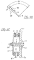
- the crankshaft as shown in FIG. 3, has no webs between the angularly offset pins 12 ', 14', only the fillets 86 'and 92' are rolled.
- a ball bearing unit 170 with a cage is arranged between the housing of the tools 68 ', 72' and enables the opposite side loads resulting from the deep rolling of the adjacent mortise grooves 86 'and 91' to be offset against one another as described in the also co-pending application 176,792 become.
- the bearing unit 170 is held by one of the tools and engages the side of the other tool so that the side loads caused by the rolling of the adjacent and opposite flutes against each other To get picked up.
- FIG. 3b shows the overlap (shaded connection surface F) that occurs between the adjacent and angularly offset crank pins 12 and 14 and on the inner grooves 88 and 90 with webs.
- the fillets 86, 88 and 90, 92 are first rolled with the tool from FIG. 2, preferably with variable rolling pressure, so that the sheet 12 '(dashed line) and 14th '(solid line) of the overlap is rolled at high pressure for deep machining and hardening of the inner grooves 88 and 90 in these areas.
- the remaining arcuate portions of the inner fillets are rolled at a lower pressure sufficient to leave the webs 94, 96 intact.
- outer grooves 86 and 92 are then rolled with the tool shown in FIG. 3a, with constant or variable pressure, so that the outer grooves 86 and 92 are completely rolled and fixed.
- This process can also be reversed, wherein, as shown in FIG. 3a, the outer fillets are first rolled and strengthened, and then the inner fillets 86 and 90 are rolled with variable pressures as described.
- the machine is shown diagrammatically as a front view, with the crankshaft 16 with radially offset pins inserted into the central lathe, and with the rows 36, 38 of the jaw units from each other and from the crankshaft by operating the drive cylinders 126 , 128 are moved away, the cylinder tubes of which are fastened to the stands 174, 176, which are fastened at their lower ends to the fixed rails 116, 118 and which in turn are fastened to the base plate 124.
- Middle tool lifting sections 180, 182 of control and counterweight cylinders 184, 186 have fork shoes at their upper ends that are rotatably attached to eyelets that extend from the upper ends of the posts 190, 192 of the upper frames of the left and right Rows of claw units extend and have lower ends that are pivotally attached at 194, 196 to the upper claws 44 and 48.
- the lifting portions can be selectively actuated to cause the jaws of the jaw units to open so that the crankshaft mounted in the center lathe 16 can be loaded into the rows of the jaw units when the rows move to the rolling position move from Figure 6.
- the claws of the units are subsequently closed by expanding the cylinders 56, 58, while the tool lifting sections 180, 182 of the control and counterweight units are disabled. Accordingly, the crank pins are gripped by the tools with a force which is low but sufficient to hold the crank shaft against rotation.
- the actual rolling of the fillets is then started by turning the crankshaft by the motor 30, the force exerted by the rolls on the fillets being increased up to the deep rolling force in that the force exerted by the cylinders 56, 58 on the corresponding claw units increases becomes.
- the rolling force can be changed during rolling since the crankshaft is driven in rotation until the fillet rolling is finished.
- the claws and tools follow the circular path of the corresponding pins to be rolled and the connected swing arms swing or swing back and forth along an arc to enable a swinging movement.
- the control and counterweight cylinders 186, 188 which is rotatably secured between the upper holding structure and the lower claw arms, can have a stroke changing section 196, 198 so that different crankshafts can be rolled with different crank pin positions.
- the cylinders 186, 188 have additional pneumatic spring counter sections 200, 202.
- the spring section is similar to a gas spring and serves to smoothly move the arms of the claw units while the fillets are being rolled.
- Figure 7 is a top view of the left and right rows of pivot arms which roll the offset crank pins shown in dashed lines in the drawing. It can be seen that this arrangement provides the rolling pressure to the claw units required cylinders can be easily used in the machine, since the cylinders and the claw units for adjacent pins are operably mounted on opposite sides of the crankshaft.
- the left row is for rolling the one set of pins and the right row is for rolling the set of pins adjacent to the first set of pins.
- the fillet rolling claws of the claw units 216, 218, 220 similar to the disclosed ones have tools such as that in FIG. 2 that can be used to roll the fillets of the main bearings while the trunnion fillets be rolled.
Landscapes
- Engineering & Computer Science (AREA)
- Mechanical Engineering (AREA)
- Life Sciences & Earth Sciences (AREA)
- Agronomy & Crop Science (AREA)
- Finish Polishing, Edge Sharpening, And Grinding By Specific Grinding Devices (AREA)
Applications Claiming Priority (2)
| Application Number | Priority Date | Filing Date | Title |
|---|---|---|---|
| US242262 | 1994-05-13 | ||
| US08/242,262 US5495738A (en) | 1994-05-13 | 1994-05-13 | Metal rolling machine with opposing banks of jaw units for working a centered workpiece and method of rolling annular fillets of workpieces |
Publications (2)
| Publication Number | Publication Date |
|---|---|
| EP0683012A1 true EP0683012A1 (fr) | 1995-11-22 |
| EP0683012B1 EP0683012B1 (fr) | 1998-08-19 |
Family
ID=22914092
Family Applications (1)
| Application Number | Title | Priority Date | Filing Date |
|---|---|---|---|
| EP95100046A Expired - Lifetime EP0683012B1 (fr) | 1994-05-13 | 1995-01-03 | Laminoir à métaux muni d'ensembles opposés d'unités à machines pour l'usinage d'une pièce centrée et procédé de laminage des gorges circulaires d'une pièce |
Country Status (4)
| Country | Link |
|---|---|
| US (1) | US5495738A (fr) |
| EP (1) | EP0683012B1 (fr) |
| CA (1) | CA2149182C (fr) |
| DE (1) | DE59503228D1 (fr) |
Cited By (3)
| Publication number | Priority date | Publication date | Assignee | Title |
|---|---|---|---|---|
| EP0750534A4 (fr) * | 1995-01-18 | 1998-11-18 | Hegenscheidt Corp | Laminage en profondeur de flancs de raccord arrondis pour manetons dedoubles de vilebrequins |
| US6666061B2 (en) | 2001-05-28 | 2003-12-23 | Hegenscheidt-Mfd Gmbh & Co. Kg | Apparatus for deep rolling of recesses and radii of crankshaft journal bearings |
| US7100413B2 (en) | 2002-07-05 | 2006-09-05 | Hegenscheidt-Mfd Gmbh & Co. Kg | Deep-rolling roller head |
Families Citing this family (13)
| Publication number | Priority date | Publication date | Assignee | Title |
|---|---|---|---|---|
| US5806184A (en) * | 1996-08-21 | 1998-09-15 | Lonero Engineering Company, Inc. | Process to manufacture upper work roll products |
| US5699692A (en) * | 1996-10-30 | 1997-12-23 | Lonero Engineering Co., Inc. | Tool mechanisms for deep rolling machines |
| DE19722308C1 (de) * | 1997-05-28 | 1998-04-16 | Hegenscheidt Mfd Gmbh | Festwalzmaschine für Kurbelwellen |
| US6272896B1 (en) | 1999-12-23 | 2001-08-14 | Daimlerchrysler Corporation | Secondary (back-up) roller design for the fillet rolling of the crankshaft |
| US6253590B1 (en) * | 2000-04-25 | 2001-07-03 | Lonero Engineering Company | Deep rolling tool mechanism with novel pin supported cage design |
| US6895793B2 (en) * | 2000-11-22 | 2005-05-24 | Ingersoll Cm Systems Llc | Apparatus and method for rolling workpieces |
| US6786073B2 (en) * | 2002-08-02 | 2004-09-07 | Ingersoll Cm Systems Llc | Apparatus and method for rolling crankshafts having split-pin bearings |
| DE10357441B3 (de) * | 2003-12-09 | 2005-03-24 | Hegenscheidt-Mfd Gmbh & Co. Kg | Festwalzrollenkopf für Split-Pin-Kurbelwellen |
| US7188500B2 (en) * | 2004-06-01 | 2007-03-13 | Ingersoll Cm Systems Llc | Apparatus and method of rolling split pin crankshafts |
| US7188497B2 (en) * | 2005-04-07 | 2007-03-13 | International Engine Intellectual Property Company, Llc | Method for straightening an eccentric shaft |
| US7588397B2 (en) * | 2005-08-31 | 2009-09-15 | Ingersoll Cm Systems Llc | Method and apparatus for machining crankshafts or camshafts |
| DE202006014371U1 (de) * | 2006-09-15 | 2007-03-08 | Hegenscheidt-Mfd Gmbh & Co. Kg | Festwalzmaschine für Kurbelwellen |
| CN104191158A (zh) * | 2014-08-08 | 2014-12-10 | 滨州海得曲轴有限责任公司 | 一种曲轴滚压装置 |
Citations (1)
| Publication number | Priority date | Publication date | Assignee | Title |
|---|---|---|---|---|
| EP0461293A1 (fr) * | 1990-06-15 | 1991-12-18 | Wilhelm Hegenscheidt Gesellschaft mbH | Procédé de galetage respectivement écrouissage de vilebrequins à excentricité différente et machine pour la mise en oeuvre de ce procédé |
Family Cites Families (2)
| Publication number | Priority date | Publication date | Assignee | Title |
|---|---|---|---|---|
| DE3037688C2 (de) * | 1980-10-06 | 1982-12-02 | Wilhelm Hegenscheidt, Gmbh, 5140 Erkelenz | Verfahren zum Festwalzen von Kurbelwellen |
| US4870845A (en) * | 1986-05-02 | 1989-10-03 | Mitsubishi Jidosha Kogyo Kabushiki Kaisha | Working apparatus for crankshaft |
-
1994
- 1994-05-13 US US08/242,262 patent/US5495738A/en not_active Expired - Lifetime
-
1995
- 1995-01-03 DE DE59503228T patent/DE59503228D1/de not_active Expired - Fee Related
- 1995-01-03 EP EP95100046A patent/EP0683012B1/fr not_active Expired - Lifetime
- 1995-05-11 CA CA002149182A patent/CA2149182C/fr not_active Expired - Fee Related
Patent Citations (1)
| Publication number | Priority date | Publication date | Assignee | Title |
|---|---|---|---|---|
| EP0461293A1 (fr) * | 1990-06-15 | 1991-12-18 | Wilhelm Hegenscheidt Gesellschaft mbH | Procédé de galetage respectivement écrouissage de vilebrequins à excentricité différente et machine pour la mise en oeuvre de ce procédé |
Cited By (3)
| Publication number | Priority date | Publication date | Assignee | Title |
|---|---|---|---|---|
| EP0750534A4 (fr) * | 1995-01-18 | 1998-11-18 | Hegenscheidt Corp | Laminage en profondeur de flancs de raccord arrondis pour manetons dedoubles de vilebrequins |
| US6666061B2 (en) | 2001-05-28 | 2003-12-23 | Hegenscheidt-Mfd Gmbh & Co. Kg | Apparatus for deep rolling of recesses and radii of crankshaft journal bearings |
| US7100413B2 (en) | 2002-07-05 | 2006-09-05 | Hegenscheidt-Mfd Gmbh & Co. Kg | Deep-rolling roller head |
Also Published As
| Publication number | Publication date |
|---|---|
| CA2149182C (fr) | 2001-07-10 |
| EP0683012B1 (fr) | 1998-08-19 |
| CA2149182A1 (fr) | 1995-11-14 |
| DE59503228D1 (de) | 1998-09-24 |
| US5495738A (en) | 1996-03-05 |
Similar Documents
| Publication | Publication Date | Title |
|---|---|---|
| EP0661137B1 (fr) | Dispositif pour la galetage de portées de vilebrequin, outil et procédé de galetage de portées de vilebrequin adjacents et décolés | |
| EP0683012B1 (fr) | Laminoir à métaux muni d'ensembles opposés d'unités à machines pour l'usinage d'une pièce centrée et procédé de laminage des gorges circulaires d'une pièce | |
| DE60133076T2 (de) | Walzverfahren und Walzwerkzeug, Walzwerkzeugaufbau und Vorrichtung | |
| DE3101924C2 (de) | Verfahren zum Bearbeiten der Lager- und Hubflächen von Kurbel- bzw. Nockenwellen durch Umfangsrundfräsen mittels Scheibenfräser | |
| DE69529342T2 (de) | Verfahren und vorrichtung zum herstellen von kurbelwellen | |
| DE212007000073U1 (de) | Vorrichtung zum Verfestigen von Werkstücken | |
| EP0318966A2 (fr) | Machine pour l'usinage de surfaces avec dispositif de positionnement d'outils | |
| DE2658970C3 (de) | Kurbelwellenfräsmaschine | |
| EP0275876B1 (fr) | Procédé et appareil de dressage d'une pièce | |
| DE60126707T2 (de) | Vorrichtung zum Bearbeiten von zylindrischen Laufflächen mittels eines Schleifbandes | |
| EP0461293A1 (fr) | Procédé de galetage respectivement écrouissage de vilebrequins à excentricité différente et machine pour la mise en oeuvre de ce procédé | |
| DE3011454C2 (de) | Verfahren für die Fertigbearbeitung von Nockenwellen | |
| DE60114623T2 (de) | Verfahren und formvorrichtung zum verformen eines hohlen werkstücks | |
| DE3011455C2 (de) | Maschine für die zweistufige Fertigbearbeitung der geschliffenen Nocken von Nockenwellen | |
| DE3885235T2 (de) | Schnellwechselbare Kühlrohre. | |
| DE2311248A1 (de) | Schleifmaschine und halterung fuer ein zu schleifendes werkstueck | |
| DE1070955B (de) | Vorrichtung zum gleich zeitigen Festwalzen der Hohlkehlen und der Laufflache an den Kurbelzapfen und Lagerstellen λ on Kurbelwellen | |
| DE3841976C1 (en) | Machine for the two-stage finish-machining of camshafts | |
| DE60115451T2 (de) | Verfahren und formvorrichtung zum verformen eines hohlen werkstücks | |
| DE10245071B4 (de) | Maschine zum Schruppen und Schlichten der Lagerzapfen von Kurbelwellen | |
| DE3333603C2 (fr) | ||
| DE10202547C1 (de) | Verfahren zum Bearbeiten von Hubzapfen einer Kurbelwelle sowie danach hergestellte Kurbelwelle | |
| DE69907368T2 (de) | Werkzeugmaschine und verfahren einer solchen maschine zum herstellen von kurbelwellen | |
| EP1372903A1 (fr) | Procede de fabrication d'un cylindre de laminage et cylindre de laminage | |
| DE3108746A1 (de) | "kurbelwellenfest- bzw. glattwalzmaschine" |
Legal Events
| Date | Code | Title | Description |
|---|---|---|---|
| PUAI | Public reference made under article 153(3) epc to a published international application that has entered the european phase |
Free format text: ORIGINAL CODE: 0009012 |
|
| AK | Designated contracting states |
Kind code of ref document: A1 Designated state(s): DE FR GB IT |
|
| RAP1 | Party data changed (applicant data changed or rights of an application transferred) |
Owner name: HEGENSCHEIDT-MFD GMBH |
|
| 17P | Request for examination filed |
Effective date: 19960422 |
|
| 17Q | First examination report despatched |
Effective date: 19970417 |
|
| GRAG | Despatch of communication of intention to grant |
Free format text: ORIGINAL CODE: EPIDOS AGRA |
|
| GRAG | Despatch of communication of intention to grant |
Free format text: ORIGINAL CODE: EPIDOS AGRA |
|
| GRAH | Despatch of communication of intention to grant a patent |
Free format text: ORIGINAL CODE: EPIDOS IGRA |
|
| GRAH | Despatch of communication of intention to grant a patent |
Free format text: ORIGINAL CODE: EPIDOS IGRA |
|
| GRAA | (expected) grant |
Free format text: ORIGINAL CODE: 0009210 |
|
| AK | Designated contracting states |
Kind code of ref document: B1 Designated state(s): DE FR GB IT |
|
| ITF | It: translation for a ep patent filed | ||
| REF | Corresponds to: |
Ref document number: 59503228 Country of ref document: DE Date of ref document: 19980924 |
|
| GBT | Gb: translation of ep patent filed (gb section 77(6)(a)/1977) |
Effective date: 19980911 |
|
| ET | Fr: translation filed | ||
| PLBE | No opposition filed within time limit |
Free format text: ORIGINAL CODE: 0009261 |
|
| STAA | Information on the status of an ep patent application or granted ep patent |
Free format text: STATUS: NO OPPOSITION FILED WITHIN TIME LIMIT |
|
| 26N | No opposition filed | ||
| PGFP | Annual fee paid to national office [announced via postgrant information from national office to epo] |
Ref country code: DE Payment date: 19991129 Year of fee payment: 6 |
|
| PGFP | Annual fee paid to national office [announced via postgrant information from national office to epo] |
Ref country code: FR Payment date: 19991130 Year of fee payment: 6 |
|
| PGFP | Annual fee paid to national office [announced via postgrant information from national office to epo] |
Ref country code: GB Payment date: 19991222 Year of fee payment: 6 |
|
| PG25 | Lapsed in a contracting state [announced via postgrant information from national office to epo] |
Ref country code: GB Free format text: LAPSE BECAUSE OF NON-PAYMENT OF DUE FEES Effective date: 20010103 |
|
| GBPC | Gb: european patent ceased through non-payment of renewal fee |
Effective date: 20010103 |
|
| PG25 | Lapsed in a contracting state [announced via postgrant information from national office to epo] |
Ref country code: FR Free format text: LAPSE BECAUSE OF NON-PAYMENT OF DUE FEES Effective date: 20010928 |
|
| PG25 | Lapsed in a contracting state [announced via postgrant information from national office to epo] |
Ref country code: DE Free format text: LAPSE BECAUSE OF NON-PAYMENT OF DUE FEES Effective date: 20011101 |
|
| REG | Reference to a national code |
Ref country code: FR Ref legal event code: ST |
|
| PG25 | Lapsed in a contracting state [announced via postgrant information from national office to epo] |
Ref country code: IT Free format text: LAPSE BECAUSE OF NON-PAYMENT OF DUE FEES;WARNING: LAPSES OF ITALIAN PATENTS WITH EFFECTIVE DATE BEFORE 2007 MAY HAVE OCCURRED AT ANY TIME BEFORE 2007. THE CORRECT EFFECTIVE DATE MAY BE DIFFERENT FROM THE ONE RECORDED. Effective date: 20050103 |