EP0683028B1 - Method of dehydrating a water containing resin melt in a twin screw extruder - Google Patents
Method of dehydrating a water containing resin melt in a twin screw extruder Download PDFInfo
- Publication number
- EP0683028B1 EP0683028B1 EP95107103A EP95107103A EP0683028B1 EP 0683028 B1 EP0683028 B1 EP 0683028B1 EP 95107103 A EP95107103 A EP 95107103A EP 95107103 A EP95107103 A EP 95107103A EP 0683028 B1 EP0683028 B1 EP 0683028B1
- Authority
- EP
- European Patent Office
- Prior art keywords
- melt
- water
- extruder
- phase
- zone
- Prior art date
- Legal status (The legal status is an assumption and is not a legal conclusion. Google has not performed a legal analysis and makes no representation as to the accuracy of the status listed.)
- Expired - Lifetime
Links
- XLYOFNOQVPJJNP-UHFFFAOYSA-N water Substances O XLYOFNOQVPJJNP-UHFFFAOYSA-N 0.000 title claims abstract description 80
- 238000000034 method Methods 0.000 title claims description 28
- 239000011347 resin Substances 0.000 title 1
- 229920005989 resin Polymers 0.000 title 1
- 239000000155 melt Substances 0.000 claims abstract description 43
- 229920000126 latex Polymers 0.000 claims abstract description 31
- 239000004816 latex Substances 0.000 claims abstract description 29
- 229920001169 thermoplastic Polymers 0.000 claims abstract description 23
- 239000000203 mixture Substances 0.000 claims abstract description 19
- 239000004416 thermosoftening plastic Substances 0.000 claims abstract description 19
- 230000005484 gravity Effects 0.000 claims abstract description 6
- 239000012071 phase Substances 0.000 claims description 52
- 230000008569 process Effects 0.000 claims description 18
- 238000005345 coagulation Methods 0.000 claims description 7
- 230000015271 coagulation Effects 0.000 claims description 7
- 238000002156 mixing Methods 0.000 claims description 6
- 239000008346 aqueous phase Substances 0.000 claims description 4
- 230000000694 effects Effects 0.000 claims description 4
- 239000011261 inert gas Substances 0.000 claims description 3
- 239000012530 fluid Substances 0.000 claims 4
- 238000000605 extraction Methods 0.000 claims 1
- 230000004941 influx Effects 0.000 claims 1
- 238000009849 vacuum degassing Methods 0.000 claims 1
- 239000007788 liquid Substances 0.000 abstract description 13
- 230000010006 flight Effects 0.000 abstract description 9
- 229920000058 polyacrylate Polymers 0.000 abstract description 3
- 239000004033 plastic Substances 0.000 description 25
- 229920003023 plastic Polymers 0.000 description 25
- 238000007872 degassing Methods 0.000 description 19
- 241000237858 Gastropoda Species 0.000 description 10
- 238000005191 phase separation Methods 0.000 description 7
- 239000002245 particle Substances 0.000 description 6
- 229920003229 poly(methyl methacrylate) Polymers 0.000 description 6
- 239000004926 polymethyl methacrylate Substances 0.000 description 6
- 230000003247 decreasing effect Effects 0.000 description 5
- 241001093575 Alma Species 0.000 description 4
- IJGRMHOSHXDMSA-UHFFFAOYSA-N Atomic nitrogen Chemical compound N#N IJGRMHOSHXDMSA-UHFFFAOYSA-N 0.000 description 4
- PPBRXRYQALVLMV-UHFFFAOYSA-N Styrene Chemical compound C=CC1=CC=CC=C1 PPBRXRYQALVLMV-UHFFFAOYSA-N 0.000 description 4
- 230000009471 action Effects 0.000 description 4
- 238000003860 storage Methods 0.000 description 4
- 239000000701 coagulant Substances 0.000 description 3
- 230000001427 coherent effect Effects 0.000 description 3
- 239000003995 emulsifying agent Substances 0.000 description 3
- 239000008187 granular material Substances 0.000 description 3
- 238000004898 kneading Methods 0.000 description 3
- 238000000926 separation method Methods 0.000 description 3
- KAKZBPTYRLMSJV-UHFFFAOYSA-N Butadiene Chemical compound C=CC=C KAKZBPTYRLMSJV-UHFFFAOYSA-N 0.000 description 2
- 238000009825 accumulation Methods 0.000 description 2
- 150000001875 compounds Chemical class 0.000 description 2
- 238000001704 evaporation Methods 0.000 description 2
- 238000001125 extrusion Methods 0.000 description 2
- 238000011049 filling Methods 0.000 description 2
- 238000000465 moulding Methods 0.000 description 2
- 229910052757 nitrogen Inorganic materials 0.000 description 2
- 238000005453 pelletization Methods 0.000 description 2
- 229920001485 poly(butyl acrylate) polymer Polymers 0.000 description 2
- 229920000642 polymer Polymers 0.000 description 2
- 238000005086 pumping Methods 0.000 description 2
- 238000007789 sealing Methods 0.000 description 2
- 239000002904 solvent Substances 0.000 description 2
- 239000000126 substance Substances 0.000 description 2
- 239000012808 vapor phase Substances 0.000 description 2
- NLHHRLWOUZZQLW-UHFFFAOYSA-N Acrylonitrile Chemical compound C=CC#N NLHHRLWOUZZQLW-UHFFFAOYSA-N 0.000 description 1
- 239000004908 Emulsion polymer Substances 0.000 description 1
- 239000004609 Impact Modifier Substances 0.000 description 1
- 239000006096 absorbing agent Substances 0.000 description 1
- 239000000654 additive Substances 0.000 description 1
- 238000005054 agglomeration Methods 0.000 description 1
- 230000002776 aggregation Effects 0.000 description 1
- 239000002216 antistatic agent Substances 0.000 description 1
- 230000008901 benefit Effects 0.000 description 1
- GCTPMLUUWLLESL-UHFFFAOYSA-N benzyl prop-2-enoate Chemical compound C=CC(=O)OCC1=CC=CC=C1 GCTPMLUUWLLESL-UHFFFAOYSA-N 0.000 description 1
- 239000003086 colorant Substances 0.000 description 1
- 239000000356 contaminant Substances 0.000 description 1
- 229920001577 copolymer Polymers 0.000 description 1
- 238000000354 decomposition reaction Methods 0.000 description 1
- 230000007423 decrease Effects 0.000 description 1
- 230000008021 deposition Effects 0.000 description 1
- 238000007599 discharging Methods 0.000 description 1
- 239000006185 dispersion Substances 0.000 description 1
- 239000003792 electrolyte Substances 0.000 description 1
- 230000008020 evaporation Effects 0.000 description 1
- 239000007789 gas Substances 0.000 description 1
- 230000009477 glass transition Effects 0.000 description 1
- 239000000314 lubricant Substances 0.000 description 1
- 230000014759 maintenance of location Effects 0.000 description 1
- 230000007257 malfunction Effects 0.000 description 1
- 238000004519 manufacturing process Methods 0.000 description 1
- 239000012803 melt mixture Substances 0.000 description 1
- 239000002991 molded plastic Substances 0.000 description 1
- 239000000178 monomer Substances 0.000 description 1
- 230000003287 optical effect Effects 0.000 description 1
- 230000000149 penetrating effect Effects 0.000 description 1
- 230000005501 phase interface Effects 0.000 description 1
- 229920000193 polymethacrylate Polymers 0.000 description 1
- 229920000915 polyvinyl chloride Polymers 0.000 description 1
- 239000004800 polyvinyl chloride Substances 0.000 description 1
- 239000011164 primary particle Substances 0.000 description 1
- 238000010008 shearing Methods 0.000 description 1
- 239000007787 solid Substances 0.000 description 1
- 239000003381 stabilizer Substances 0.000 description 1
- 239000012815 thermoplastic material Substances 0.000 description 1
- 238000003809 water extraction Methods 0.000 description 1
Images


Classifications
-
- C—CHEMISTRY; METALLURGY
- C08—ORGANIC MACROMOLECULAR COMPOUNDS; THEIR PREPARATION OR CHEMICAL WORKING-UP; COMPOSITIONS BASED THEREON
- C08F—MACROMOLECULAR COMPOUNDS OBTAINED BY REACTIONS ONLY INVOLVING CARBON-TO-CARBON UNSATURATED BONDS
- C08F6/00—Post-polymerisation treatments
- C08F6/14—Treatment of polymer emulsions
- C08F6/22—Coagulation
-
- B—PERFORMING OPERATIONS; TRANSPORTING
- B29—WORKING OF PLASTICS; WORKING OF SUBSTANCES IN A PLASTIC STATE IN GENERAL
- B29B—PREPARATION OR PRETREATMENT OF THE MATERIAL TO BE SHAPED; MAKING GRANULES OR PREFORMS; RECOVERY OF PLASTICS OR OTHER CONSTITUENTS OF WASTE MATERIAL CONTAINING PLASTICS
- B29B7/00—Mixing; Kneading
- B29B7/30—Mixing; Kneading continuous, with mechanical mixing or kneading devices
- B29B7/34—Mixing; Kneading continuous, with mechanical mixing or kneading devices with movable mixing or kneading devices
- B29B7/38—Mixing; Kneading continuous, with mechanical mixing or kneading devices with movable mixing or kneading devices rotary
- B29B7/46—Mixing; Kneading continuous, with mechanical mixing or kneading devices with movable mixing or kneading devices rotary with more than one shaft
- B29B7/48—Mixing; Kneading continuous, with mechanical mixing or kneading devices with movable mixing or kneading devices rotary with more than one shaft with intermeshing devices, e.g. screws
-
- B—PERFORMING OPERATIONS; TRANSPORTING
- B29—WORKING OF PLASTICS; WORKING OF SUBSTANCES IN A PLASTIC STATE IN GENERAL
- B29B—PREPARATION OR PRETREATMENT OF THE MATERIAL TO BE SHAPED; MAKING GRANULES OR PREFORMS; RECOVERY OF PLASTICS OR OTHER CONSTITUENTS OF WASTE MATERIAL CONTAINING PLASTICS
- B29B7/00—Mixing; Kneading
- B29B7/74—Mixing; Kneading using other mixers or combinations of mixers, e.g. of dissimilar mixers ; Plant
- B29B7/7461—Combinations of dissimilar mixers
-
- B—PERFORMING OPERATIONS; TRANSPORTING
- B29—WORKING OF PLASTICS; WORKING OF SUBSTANCES IN A PLASTIC STATE IN GENERAL
- B29B—PREPARATION OR PRETREATMENT OF THE MATERIAL TO BE SHAPED; MAKING GRANULES OR PREFORMS; RECOVERY OF PLASTICS OR OTHER CONSTITUENTS OF WASTE MATERIAL CONTAINING PLASTICS
- B29B7/00—Mixing; Kneading
- B29B7/80—Component parts, details or accessories; Auxiliary operations
- B29B7/84—Venting or degassing ; Removing liquids, e.g. by evaporating components
- B29B7/842—Removing liquids in liquid form
-
- B—PERFORMING OPERATIONS; TRANSPORTING
- B29—WORKING OF PLASTICS; WORKING OF SUBSTANCES IN A PLASTIC STATE IN GENERAL
- B29B—PREPARATION OR PRETREATMENT OF THE MATERIAL TO BE SHAPED; MAKING GRANULES OR PREFORMS; RECOVERY OF PLASTICS OR OTHER CONSTITUENTS OF WASTE MATERIAL CONTAINING PLASTICS
- B29B7/00—Mixing; Kneading
- B29B7/80—Component parts, details or accessories; Auxiliary operations
- B29B7/84—Venting or degassing ; Removing liquids, e.g. by evaporating components
- B29B7/845—Venting, degassing or removing evaporated components in devices with rotary stirrers
-
- B—PERFORMING OPERATIONS; TRANSPORTING
- B29—WORKING OF PLASTICS; WORKING OF SUBSTANCES IN A PLASTIC STATE IN GENERAL
- B29C—SHAPING OR JOINING OF PLASTICS; SHAPING OF MATERIAL IN A PLASTIC STATE, NOT OTHERWISE PROVIDED FOR; AFTER-TREATMENT OF THE SHAPED PRODUCTS, e.g. REPAIRING
- B29C48/00—Extrusion moulding, i.e. expressing the moulding material through a die or nozzle which imparts the desired form; Apparatus therefor
- B29C48/25—Component parts, details or accessories; Auxiliary operations
- B29C48/36—Means for plasticising or homogenising the moulding material or forcing it through the nozzle or die
- B29C48/375—Plasticisers, homogenisers or feeders comprising two or more stages
- B29C48/385—Plasticisers, homogenisers or feeders comprising two or more stages using two or more serially arranged screws in separate barrels
-
- B—PERFORMING OPERATIONS; TRANSPORTING
- B29—WORKING OF PLASTICS; WORKING OF SUBSTANCES IN A PLASTIC STATE IN GENERAL
- B29C—SHAPING OR JOINING OF PLASTICS; SHAPING OF MATERIAL IN A PLASTIC STATE, NOT OTHERWISE PROVIDED FOR; AFTER-TREATMENT OF THE SHAPED PRODUCTS, e.g. REPAIRING
- B29C48/00—Extrusion moulding, i.e. expressing the moulding material through a die or nozzle which imparts the desired form; Apparatus therefor
- B29C48/25—Component parts, details or accessories; Auxiliary operations
- B29C48/36—Means for plasticising or homogenising the moulding material or forcing it through the nozzle or die
- B29C48/395—Means for plasticising or homogenising the moulding material or forcing it through the nozzle or die using screws surrounded by a cooperating barrel, e.g. single screw extruders
- B29C48/40—Means for plasticising or homogenising the moulding material or forcing it through the nozzle or die using screws surrounded by a cooperating barrel, e.g. single screw extruders using two or more parallel screws or at least two parallel non-intermeshing screws, e.g. twin screw extruders
- B29C48/41—Intermeshing counter-rotating screws
-
- B—PERFORMING OPERATIONS; TRANSPORTING
- B29—WORKING OF PLASTICS; WORKING OF SUBSTANCES IN A PLASTIC STATE IN GENERAL
- B29C—SHAPING OR JOINING OF PLASTICS; SHAPING OF MATERIAL IN A PLASTIC STATE, NOT OTHERWISE PROVIDED FOR; AFTER-TREATMENT OF THE SHAPED PRODUCTS, e.g. REPAIRING
- B29C48/00—Extrusion moulding, i.e. expressing the moulding material through a die or nozzle which imparts the desired form; Apparatus therefor
- B29C48/25—Component parts, details or accessories; Auxiliary operations
- B29C48/36—Means for plasticising or homogenising the moulding material or forcing it through the nozzle or die
- B29C48/50—Details of extruders
- B29C48/76—Venting, drying means; Degassing means
-
- B—PERFORMING OPERATIONS; TRANSPORTING
- B29—WORKING OF PLASTICS; WORKING OF SUBSTANCES IN A PLASTIC STATE IN GENERAL
- B29B—PREPARATION OR PRETREATMENT OF THE MATERIAL TO BE SHAPED; MAKING GRANULES OR PREFORMS; RECOVERY OF PLASTICS OR OTHER CONSTITUENTS OF WASTE MATERIAL CONTAINING PLASTICS
- B29B7/00—Mixing; Kneading
- B29B7/74—Mixing; Kneading using other mixers or combinations of mixers, e.g. of dissimilar mixers ; Plant
- B29B7/7476—Systems, i.e. flow charts or diagrams; Plants
- B29B7/7495—Systems, i.e. flow charts or diagrams; Plants for mixing rubber
-
- B—PERFORMING OPERATIONS; TRANSPORTING
- B29—WORKING OF PLASTICS; WORKING OF SUBSTANCES IN A PLASTIC STATE IN GENERAL
- B29B—PREPARATION OR PRETREATMENT OF THE MATERIAL TO BE SHAPED; MAKING GRANULES OR PREFORMS; RECOVERY OF PLASTICS OR OTHER CONSTITUENTS OF WASTE MATERIAL CONTAINING PLASTICS
- B29B9/00—Making granules
- B29B9/02—Making granules by dividing preformed material
- B29B9/06—Making granules by dividing preformed material in the form of filamentary material, e.g. combined with extrusion
-
- B—PERFORMING OPERATIONS; TRANSPORTING
- B29—WORKING OF PLASTICS; WORKING OF SUBSTANCES IN A PLASTIC STATE IN GENERAL
- B29C—SHAPING OR JOINING OF PLASTICS; SHAPING OF MATERIAL IN A PLASTIC STATE, NOT OTHERWISE PROVIDED FOR; AFTER-TREATMENT OF THE SHAPED PRODUCTS, e.g. REPAIRING
- B29C48/00—Extrusion moulding, i.e. expressing the moulding material through a die or nozzle which imparts the desired form; Apparatus therefor
- B29C48/03—Extrusion moulding, i.e. expressing the moulding material through a die or nozzle which imparts the desired form; Apparatus therefor characterised by the shape of the extruded material at extrusion
-
- B—PERFORMING OPERATIONS; TRANSPORTING
- B29—WORKING OF PLASTICS; WORKING OF SUBSTANCES IN A PLASTIC STATE IN GENERAL
- B29K—INDEXING SCHEME ASSOCIATED WITH SUBCLASSES B29B, B29C OR B29D, RELATING TO MOULDING MATERIALS OR TO MATERIALS FOR MOULDS, REINFORCEMENTS, FILLERS OR PREFORMED PARTS, e.g. INSERTS
- B29K2021/00—Use of unspecified rubbers as moulding material
Definitions
- the invention relates to a method for dewatering a two-phase liquid mixture of a thermoplastic Plastic melt and a water phase in one counter rotating twin screw extruder and pulling off the aqueous phase from the extruder in liquid form.
- the procedure is part of a procedure for Dewatering a latex of a thermoplastic in a counter rotating twin screw extruder.
- the plastic is in shape in the dispersion used of latex particles in the coherent water phase equally distributed.
- the primary particles of latex coagulate under the influence of shear forces in the Extruder at a temperature in the thermoplastic range of the plastic and form a melt phase, which with the Water phase is mixed.
- Occurs in the screw extruder a phase separation based on a pressure gradient is based.
- the pressure gradient is determined by design features of the extruder, e.g. in the conveying direction decreasing screw pitch or decreasing free Cross-sectional areas due to increasing core diameter or decreasing cylinder and screw diameter or through a storage zone arranged behind a screw section with kneading or mixing elements.
- the pressure gradient causes a backflow in which the water phase due to its lower viscosity a higher flow rate reached as the melt phase. So there is one preferred backflow of the water phase.
- the melt phase collects in the zone of highest pressure during the water phase flows increasingly back into the zone of lower pressure. The However, phase separation is hampered if that back-flowing water as a coherent water phase collects because of the action of the snails is constantly mixed back into the plastic melt.
- the separation of the water phase in liquid form has before Evaporation of the entire water phase has the advantage that dissolved components, such as coagulants or Emulsifiers to be removed at the same time and that the Energy expenditure for evaporating the water and for pumping large steam volumes is saved.
- the invention is based, with one Process for dewatering a two-phase liquid Mixture of a thermoplastic melt and a water phase, especially a latex coagulum, in a counter rotating twin screw extruder problems of to avoid or reduce the described type.
- a two-phase liquid Mixture of a thermoplastic melt and a water phase, especially a latex coagulum in a counter rotating twin screw extruder problems of to avoid or reduce the described type.
- the watery Phase is in from the dewatering zone of the extruder subtracted in liquid form.
- the melt is in the Drainage zone divided into several sections that each promoted in separate screw flights become.
- the melt phase is at least one of these worm threads in the feed gap of the Twin screw forming a narrowly localized Pressure gradients to form a coherent melt cake jammed.
- the water is in front of the border of the Melt cake under the action of gravity like this flow down through at least one drain opening let the melt cake not with a connected water phase is in contact.
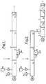
- the squeezed water phase can then best be drained off if the screw axes (4,5) are in a horizontal Level S-S are arranged in opposite directions rotate that the melt cake (7) below this level S-S is stowed and the water through a drain opening (8) allowed to drain off at the lowest point of the extruder wall becomes.
- the filling of the screw flights must then be limited be that the melt cake is not to the deepest Point of the extruder wall extends, because otherwise it is there would close the opening.
- the melt cake builds up above the direction of rotation Level of contact. It may then be necessary to have one to form larger melt cakes to drain the water in Ensure direction of gravity. The In this case, the drainage effect can result from Backmixing may be slightly less.
- the melt does not come out until the end of the drainage zone which no longer escapes water into a storage area led where the screw flights fill with melt and sealing the drainage zone from the reduced pressure of the subsequent degassing zone is formed becomes.
- the method of the invention is suitable for dewatering latices. They generally contain 30 to 50% by weight of dispersed plastic particles, the average particle size of which can be, for example, 100 to 500 nm. Accordingly, the water phase makes up 70 to 50% by weight; it generally contains dissolved emulsifiers, optionally coagulants or other auxiliaries and foreign substances.
- the latex particles consist of thermoplastic materials that can be processed in the melt on an extruder. These include thermoplastics with glass transition temperatures of 50 to 300 o C or a temperature range in the melt state in which they are sufficiently resistant to decomposition. The melt temperature in the twin-screw extruder is usually between 100 and 250 o C.
- thermoplastics are Copolymers based on butadiene, styrene and optionally acrylonitrile and polyvinyl chloride, Polyacrylates or polymethacrylates.
- Another important one Class are latices of multi-phase thermoplastic Plastics containing latex particles with a thermoplastic hard phase and a cross-linked tough phase. You can use a another thermoplastic that is in solid or molten form in the twin screw extruder is introduced and with the plastic of the hard phase of the Latex matches or is compatible with it, be mixed.
- the plastic is made of Hard phase predominantly made of polymethyl methacrylate and Toughened plastic predominantly made of cross-linked Polybutyl acrylate, which is used for the purpose of approximation of the optical refractive index to that of polymethyl methacrylate also be copolymerized with styrene or benzyl acrylate can.
- Typical mixtures of this type contain e.g. 4 to 50 %
- the Multi-phase latex plastic in which the Polybutyl acrylate content 2 to 80 wt .-% and Make up 20 to 98% by weight of polymethyl methacrylate can, as well as 2 to 60 wt .-% of the thermoplastic Polymethyl methacrylate plastic. If this is not in molten form is introduced, it is also possible the latex of the multi-phase plastic with a Mix and polymethyl methacrylate latex Latex mix according to the method of the invention to process.
- Twin screw extruder (1) contains parallel, intermeshing snails (2, 3) so that in each case the screw flights of one snail into the Engage the worm threads of the other worm.
- the two snails run closely along the entire length next to each other and form one at the screw gap (6) Closure through which practically no melt passes.
- the screw flights are through the Snail gap (6) spatially separated from each other.
- the in each cake contains melt cake (7) is forcibly without any significant mixing with the Amounts of melt in adjacent gears at every turn conveyed a helix turn.
- the closely meshing one Twin screw extruder is therefore "stiff in conveyance", which is the Fluctuation counteracts the phase boundary.
- the twin screw extruder can be used for production purposes Screw diameters from 55 to 300 mm and a length from 30 have up to 50 times the screw diameter.
- the optimal degree of filling of the screw turns in The drainage zone can be adjusted by coordinating the Form of latex and possibly plastic melt amount of plastic introduced with the conveyor and Adjust the extruder output precisely.
- the deposition of the plastic from the latex is not Part of the claimed process, but this goes usually ahead. It initially leads to a liquid Coagulate with melt particles or - distributed therein droplet. Under the shear in the coagulation zone (10) of the extruder unite more and more originally formed droplets of melt too steady growing, suspended in the water phase Melt agglomerations. By changing from Conveying, kneading and accumulation zones can accelerate this process become. This mixture of one melt and one Water phase forms the starting point of the process of Invention.
- the drainage process is suitable for continuous operation under constant conditions.
- the latex or one liquid precoagulate produced therefrom is by means of a suitable metering device (16), e.g. one Diaphragm pump, at one or more points in the extruder (1) introduced. If the latex or pre-coagulate alone processed, it can be inserted at the rear end become. In contrast, it becomes a mixture with another generated thermoplastic, so this can over a dosing device (17) from a storage container (18) drawn in as granules, melted and plasticized become.
- the plastic is preferably used as a melt pressed in. In the drainage zone (11) the mixes plastic separated from the latex or the pre-coagulate with the existing melt.
- the phase separation is carried out at a sufficiently high pressure so that the water phase does not evaporate even at the lowest pressure in the region of the pressure gradient.
- a pressure of 10 to 40 bar is required in the dewatering zone.
- the operating pressure can optionally be adjusted by pressurized inert gas; for example, nitrogen can be injected via a line (14) at a pressure above the vapor pressure of the water phase.
- the separated Water phase while maintaining the pressure above at least one discharge opening (8) in the extruder wall in a drainage vessel (19) to an expansion valve (20) headed.
- the Melted by injecting cold water and thereby increasing their viscosity. With that the Inclination of the melt diminishes, along with the water in to flow into the discharge opening.
- the Discharge opening (8) in the lower wall so that the deposited aqueous phase under the action of Gravity emerges from the twin screw extruder.
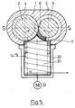
- One can also in the lower wall of the twin-screw extruder has a cylindrical exhaust duct Use (30) with a retaining screw (31), which is by means of of the drive (32) if necessary in the event of a malfunction penetrating melt into the twin screw channel promoted back.
- a pressure pot (33) held under pressure, from which the separated water phase over a Pressure maintaining valve (34) emerges.
- the separation of water-soluble secondary components, such as emulsifiers or Electrolytes, from the melt can be completed, if the dewatered melt in an additional Mixing zone of pure water or another volatile Solvent that removes the contaminants but not the Plastic dissolves, added and in another Drainage zone separated in the same way as before becomes.
- the remaining water or solvent is in the subsequent degassing zone (12) at normal pressure and / or largely evaporated at a pressure of 0.01 to 0.99 bar, if necessary in several stages with decreasing pressures. It has a water content below 0.1% by weight, preferably of 0.03 to 0.06% by weight is aimed for.
- the Melt in the final pump zone (13) to one Extrusion brought suitable melt pressure and extruded.
- phase separation the required size and Uniformity of pressure can be safely maintained, if the dewatering zone (11) from the degassing zone (12) is separated by equipment.
- the functions of phase separation and the degassing are in this case on two extruders distributed, only for the first function a combing Twin screw extruder is required.
- the pressure in the end the drainage zone (11), which has a pumping zone (21) can be connected downstream, can be by means of a Throttle valve (22) for the discharged melt exactly to adjust.
- the melt is in via a line (23) introduced a conventional degassing extruder.
- the latex is supplied with a diaphragm metering pump (16) Mass flow of 10 kg / h in the cylinder of a tight intermeshing, counter-rotating twin-screw extruder (1) pumped.
- the screw axes (4,5) lie in one horizontal plane S-S; the direction of rotation is below the level S-S to the screw gap (6).
- the Screw diameters are 34 mm.
- the snails (2,3) are three-course with a pitch of 30 mm.
- the coagulation zone (10, Fig.2) has a length of 600 mm and is kept at 230 o C; the drainage zone (11) has a length of 120 mm and is operated with a cylinder temperature of 210 o C.
- the two cylinders are on lowest point with 2 mm wide and 60 mm long slots open. Under these two openings is the Collection container (19) mounted pressure-tight.
- the collection container (19) for the separated water is via line (14) under a nitrogen pressure of 40 bar held.
- a liquid level control is used the valve (20) withdrawn a quantity of water of 5.27 kg / h.
- the water contains 0.4% by weight of organic substance.
- About the Valve (22) is the inflow to the downstream Degassing extruder controlled so that in front of the valve Melt pressure of 80 bar is constantly maintained. Of the Inflow into the degassing extruder contains 8% by weight of water.
Landscapes
- Engineering & Computer Science (AREA)
- Mechanical Engineering (AREA)
- Chemical & Material Sciences (AREA)
- Health & Medical Sciences (AREA)
- Chemical Kinetics & Catalysis (AREA)
- Medicinal Chemistry (AREA)
- Polymers & Plastics (AREA)
- Organic Chemistry (AREA)
- Processing And Handling Of Plastics And Other Materials For Molding In General (AREA)
- Extrusion Moulding Of Plastics Or The Like (AREA)
- Addition Polymer Or Copolymer, Post-Treatments, Or Chemical Modifications (AREA)
Abstract
Description
Die Erfindung betrifft ein Verfahren zum Entwässern eines zweiphasigen flüssigen Gemisches aus einer thermoplastischen Kunststoffschmelze und einer Wasserphase in einem gegenläufigen Doppelschneckenextruder und Abziehen der wäßrigen Phase aus dem Extruder in flüssiger Form. In der Regel ist das Verfahren Bestandteil eines Verfahrens zum Entwässern eines Latex eines thermoplastischen Kunststoffes in einem gegenläufigen Doppelschneckenextruder.The invention relates to a method for dewatering a two-phase liquid mixture of a thermoplastic Plastic melt and a water phase in one counter rotating twin screw extruder and pulling off the aqueous phase from the extruder in liquid form. In the As a rule, the procedure is part of a procedure for Dewatering a latex of a thermoplastic in a counter rotating twin screw extruder.
In der eingesetzten Dispersion ist der Kunststoff in Form von Latexteilchen in der zusammenhängenden Wasserphase gleichmäßig verteilt. Die Primärteilchen des Latex koagulieren unter der Einwirkung von Scherkräften im Extruder bei einer Temperatur im thermoplastischen Bereich des Kunststoffs und bilden eine Schmelzephase, die mit der Wasserphase vermischt ist. In dem Schneckenextruder tritt eine Phasentrennung auf, die auf einem Druckgradienten beruht. Der Druckgradient wird durch konstruktive Merkmale des Extruders hervorgerufen, z.B. in Förderrichtung abnehmende Schneckensteigung oder abnehmende freie Querschnittsflächen durch zunehmenden Kerndurchmesser oder abnehmenden Zylinder- und Schneckendurchmesser oder durch eine hinter einem Schneckenabschnitt angeordnete Stauzone mit Knet- oder Mischelementen. Der Druckgradient verursacht eine Rückströmung, bei der die Wasserphase aufgrund ihrer niedrigeren Viskosität eine höhere Strömungsgeschwindigkeit erreicht als die Schmelzephase. Es kommt also zu einer bevorzugten Rückströmung der Wasserphase. Auf diesem Effekt beruht die Phasentrennung: die Schmelzephase sammelt sich in der Zone des höchsten Druckes, während die Wasserphase verstärkt in die Zone geringeren Druckes zurückströmt. Die Phasentrennung wird jedoch behindert, wenn sich das rückströmende Wasser als zusammenhängende Wasserphase sammelt, weil es dann durch die Wirkung der Schnecken ständig wieder in die Kunststoffschmelze eingemischt wird.The plastic is in shape in the dispersion used of latex particles in the coherent water phase equally distributed. The primary particles of latex coagulate under the influence of shear forces in the Extruder at a temperature in the thermoplastic range of the plastic and form a melt phase, which with the Water phase is mixed. Occurs in the screw extruder a phase separation based on a pressure gradient is based. The pressure gradient is determined by design features of the extruder, e.g. in the conveying direction decreasing screw pitch or decreasing free Cross-sectional areas due to increasing core diameter or decreasing cylinder and screw diameter or through a storage zone arranged behind a screw section with kneading or mixing elements. The pressure gradient causes a backflow in which the water phase due to its lower viscosity a higher flow rate reached as the melt phase. So there is one preferred backflow of the water phase. On this effect is based on phase separation: the melt phase collects in the zone of highest pressure during the water phase flows increasingly back into the zone of lower pressure. The However, phase separation is hampered if that back-flowing water as a coherent water phase collects because of the action of the snails is constantly mixed back into the plastic melt.
Es ist seit langem bekannt, durch Koagulation und Entwässerung eines Kunststoff-Latex in einem Extruder eine thermoplastische Kunststoffschmelze zu gewinnen und diese gegebenenfalls gleichzeitig mit einem anderen thermoplastischen Kunststoff zu vermischen. Gemäß DE-A 20 37 784 erfolgt die Entwässerung in drei Stufen unter absteigendem Druck über die Dampfphase. Nach DE-A 22 43 696 wird die Koagulation unter einem Druck durchgeführt, bei dem das abgeschiedene Wasser flüssig bleibt. Aus dem Gemisch der Kunststoffschmelze mit der abgeschiedenen Wasserphase wird die Kunststoffschmelze unter Aufbau eines Druckgradienten strömungsabwärts gefördert und das darin befindliche Wasser ausgepreßt und zurückbefördert. Ein Teil des Gemisches aus Schmelze und Wasser dringt in eine seitlich an den Extruder angesetzte Entwässerungsleitung ein, aus der die Schmelzeanteile mittels einer Stopfschnecke in den Extruderkanal zurückbefördert werden, während die Wasserphase über ein Druckhalteventil austritt.It has long been known through coagulation and Dewatering a plastic latex in an extruder to win thermoplastic melt and this if necessary, simultaneously with another mix thermoplastic. According to DE-A 20 37 784 the drainage takes place in three stages descending pressure over the vapor phase. According to DE-A 22 43 696 the coagulation is carried out under a pressure at which the separated water remains liquid. From the mixture of Plastic melt with the separated water phase the plastic melt while building up a pressure gradient downstream and the water contained therein pressed out and transported back. Part of the mixture Melt and water penetrate into the side of the extruder attached drainage line from which the Melt proportions by means of a stuffing screw in the Extruder channel are conveyed back during the Water phase emerges via a pressure control valve.
Die Abtrennung der Wasserphase in flüssiger Form hat vor der Verdampfung der gesamten Wasserphase den Vorteil, daß gelöste Bestandteile, wie Koagulationsmittel oder Emulgatoren, zugleich entfernt werden und daß der Energieaufwand zum Verdampfen des Wassers und zum Abpumpen großer Dampfvolumina erspart wird.The separation of the water phase in liquid form has before Evaporation of the entire water phase has the advantage that dissolved components, such as coagulants or Emulsifiers to be removed at the same time and that the Energy expenditure for evaporating the water and for pumping large steam volumes is saved.
Gemäß US-A 4,136,251 wird für ein solches Verfahren ein dicht kämmender Doppelschneckenextruder verwendet. Das Gemisch aus Schmelze und Wasser wird über eine Engstelle in eine Entspannungszone des Extruders gefördert, aus der das Wasser über eine oben angesetzte Entwässerungsleitung mit Stopfschnecke bei mäßigem Druck austritt. Die zurückbleibende Schmelze wird zur vollständigen Entwässerung in eine weitere Druckzone und von dort in eine Entgasungszone gefördert. In der US-A 4,148,991 wird eine Verfahrensvariante beschrieben, bei der ein Kunststofflatex allein ohne zugesetzte Schmelze eines thermoplastischen Kunststoffes entwässert wird.According to US-A 4,136,251, such a method is used tightly intermeshing twin screw extruder used. The Mixture of melt and water is in a narrow point in promoted a relaxation zone of the extruder, from which the Water via a drainage pipe attached at the top Darning screw exits at moderate pressure. The remaining melt becomes complete drainage to another pressure zone and from there to one Degassing zone promoted. In US-A 4,148,991 a Process variant described, in which a plastic latex alone without the added melt of a thermoplastic Plastic is dewatered.
Allen beschriebenen Verfahren ist gemeinsam, daß das Gemisch aus der Kunststoffschmelze und der abgeschiedenen Wasserphase in eine Druckzone gefördert wird, die sich über mehrere Schneckengänge erstreckt und aus der das Wasser mit zunehmendem Druck stärker ausgepreßt und rückwärtgefördert wird. Die Schneckengänge sind mit diesem Schmelze-Wasser-Gemisch gefüllt, wobei der Wasseranteil in Richtung zunehmenden Druckes abnimmt. Je länger eine solche Druckzone ist, um so mehr Wasser wird ständig wieder in die Schmelzephase eingepreßt, so daß eine vollständige Entwässerung nur schwer zu erreichen ist.All of the methods described have in common that the mixture from the plastic melt and the deposited Water phase is conveyed into a pressure zone, which is about stretches several snails and out of which the water with increasing pressure squeezed out and promoted backwards becomes. The worm threads are with this melt-water mixture filled, the water content in the direction increasing pressure decreases. The longer such Pressure zone is, the more water is constantly being returned to the Melted phase, so that a complete Drainage is difficult to achieve.
Der Wasserabzug über einen Seitenkanal mit Stopfschnecke muß in einem Bereich erfolgen, wo das Wasser die zusammenhängende und die Schmelze die darin verteilte Phase bilden. Liegt der Seitenkanal zu nahe an der Eintrittsstelle des Latex, so gehen mit dem abgepreßten Wasser beträchtliche Anteile des noch unkoagulierten Latex-Kunststoffes verloren. Daher wird das Wasser an einer möglichst weit strömungsabwärts gelegenen Zone abgenommen. Die Phasenumkehrungsgrenze, wo die Schmelze-in-Wasser-Mischung in eine Wasser-in-Schmelze-Mischung übergeht, ist jedoch wegen Instabilität der Förderwirkung während des laufenden Betriebs nicht ortsfest. Zieht sie sich bis zum Ansatzpunkt des Entwässerungskanals zurück, so dringt dort verstärkt Schmelze ein, die durch die Wirkung der Stopfschnecken manchmal nicht oder schwer zurückgehalten werden kann. Der Betrieb eines Entwässerungsextruders verlangt daher laufende aufmerksame Beobachtung und muß trotz aller Sorgfalt häufig zur Behebung von Störungen unterbrochen werden.The water drainage via a side channel with a stuffing screw must be done in an area where the water contiguous and the melt the distributed phase form. If the side channel is too close to the entry point of latex, so go with the squeezed water considerable Parts of the still uncoagulated latex plastic lost. Therefore, the water is as wide as possible downstream zone decreased. The Phase inversion limit where the melt-in-water mixture passes into a water-in-melt mixture, however due to instability of the funding effect during the current Operating not stationary. It pulls up to the starting point of the drainage channel back, so penetrates there intensified Melt one by the action of the snails sometimes not or difficult to hold back. Of the Operation of a dewatering extruder therefore requires ongoing careful observation and must, despite all care, be frequent interrupted to remedy faults.
Der Erfindung liegt die Aufgabe zugrunde, bei einem Verfahren zum Entwässern eines zweiphasigen flüssigen Gemisches aus einer thermoplastischen Kunststoffschmelze und einer Wasserphase, insbesondere eines Latex-Koagulats, in einem gegenläufigen Doppelschneckenextruder Probleme der beschriebenen Art zu vermeiden oder zu vermindern. Durch eine gesteigerte Entwässerungsleistung soll der Mengendurchsatz erhöht und der über die Dampfphase zu entgasende Wasseranteil vermindert werden. The invention is based, with one Process for dewatering a two-phase liquid Mixture of a thermoplastic melt and a water phase, especially a latex coagulum, in a counter rotating twin screw extruder problems of to avoid or reduce the described type. By an increased drainage capacity should Volume throughput increased and the vapor phase too degassing water content can be reduced.
Ebenso wie die bekannten Entwässerungsverfahren wird das Verfahren der Erfindung unter einem Druck ausgeführt, der größer ist als der Wasserdampfdruck bei der Temperatur der Schmelze des thermoplastischen Kunststoffes. Die wäßrige Phase wird aus der Entwässerungszone des Extruders in flüssiger Form abgezogen. Die Schmelze ist in der Entwässerungszone in mehrere Abschnitte unterteilt, die jeweils in voneinander getrennten Schneckengängen gefördert werden. Erfindungsgemäß wird die Schmelzephase in wenigstens einem dieser Schneckengänge im Einzugsspalt der Doppelschnecke unter Bildung eines örtlich eng begrenzten Druckgradienten zu einem zusammenhängenden Schmelzekuchen gestaut. Dabei wird das Wasser vor der Grenze des Schmelzekuchens unter der Wirkung der Schwerkraft derart nach unten durch wenigstens eine Abzugsöffnung abfließen gelassen, daß der Schmelzekuchen nicht mit einer zusammenhängenden Wasserphase in Berührung steht.Just like the well-known drainage processes, it will Process of the invention carried out under a pressure that is greater than the water vapor pressure at the temperature of the Melt of the thermoplastic. The watery Phase is in from the dewatering zone of the extruder subtracted in liquid form. The melt is in the Drainage zone divided into several sections that each promoted in separate screw flights become. According to the invention, the melt phase is at least one of these worm threads in the feed gap of the Twin screw forming a narrowly localized Pressure gradients to form a coherent melt cake jammed. The water is in front of the border of the Melt cake under the action of gravity like this flow down through at least one drain opening let the melt cake not with a connected water phase is in contact.
Zur Erläuterung der Wirkungsweise wird auf die Figuren 1 bis
5 verwiesen.
Im Gegensatz zu bekannten Entwässerungsverfahren wird die Schmelze nicht vor einer Widerstandszone der Schnecken aufgestaut, sondern in jedem einzelnen Schneckengang der Entwässerungszone. Dadurch ist der Druckgradient auf einen engen Raum begrenzt und wesentlich steiler als in einer herkömmlichen, über mehrere Schneckenwindungen erstreckten Druckzone. Durch die dicht kämmende Anordnung der Doppelschnecken ist der Schmelzedurchtritt im Schneckenspalt (6) vernachlässigbar, so daß sich in jedem Schneckengang in dem Zwickel vor dem Schneckenspalt ein dichter Schmelzekuchen (7) ansammelt und mit der Rotataion der Schnecken linear weiterbefördert wird. Unter der Einwirkung des örtlich eng begrenzten Druckgradienten tritt in den teilgefüllten Schneckengängen eine intensive Entwässerung ein. Wichtig ist, daß das abgepreßte Wasser unmittelbar ablaufen kann und nicht aus einer vor der Grenze des Schmelzekuchens stehenden geschlossenen Wasserphase ständig wieder eingewalkt wird. Der Schmelzekuchen steht vielmehr überwiegend mit einer Dampf- bzw. Gasphase in Berührung.In contrast to known drainage processes, the Do not melt in front of a snail's resistance zone pent up, but in every single worm gear Drainage zone. This is the pressure gradient on one limited space and much steeper than in a conventional, extending over several screw turns Pressure zone. Due to the closely intermeshing arrangement of the Twin screws is the melt passage in the screw gap (6) negligible, so that in each worm gear in the gusset in front of the snail gap Melt cake (7) accumulates and with the rotation of the Screws are conveyed linearly. Under the influence of the locally limited pressure gradient occurs in the partially filled screw flights an intensive drainage on. It is important that the squeezed water immediately can run out and not from a before the border of the Melt cake standing closed water phase constantly is rolled in again. The melt cake stands rather mainly in contact with a vapor or gas phase.
Die abgepreßte Wasserphase kann dann am besten abgeleitet werden, wenn die Schneckenachsen (4,5) in einer waagerechten Ebene S-S angeordnet sind und in der Weise gegenläufig rotieren, daß der Schmelzekuchen (7) unterhalb dieser Ebene S-S gestaut wird und das Wasser durch eine Abzugsöffnung (8) am tiefsten Punkt der Extruderwandung abfließen gelassen wird. Die Füllung der Schneckengänge muß dann so begrenzt sein, daß sich der Schmelzekuchen nicht bis zum tiefsten Punkt der Extruderwandung erstreckt, weil er sonst die dort liegende Abzugsöffnung verschließen würde. Bei umgekehrter Drehrichtung staut sich der Schmelzekuchen oberhalb der Berührungsebene. Es kann dann erforderlich sein, einen größeren Schmelzekuchen zu bilden, um den Wasserablauf in Richtung der Schwerkraft zu gewährleisten. Die Entwässerungswirkung kann in diesem Falle infolge von Rückvermischung etwas geringer sein.The squeezed water phase can then best be drained off if the screw axes (4,5) are in a horizontal Level S-S are arranged in opposite directions rotate that the melt cake (7) below this level S-S is stowed and the water through a drain opening (8) allowed to drain off at the lowest point of the extruder wall becomes. The filling of the screw flights must then be limited be that the melt cake is not to the deepest Point of the extruder wall extends, because otherwise it is there would close the opening. In reverse The melt cake builds up above the direction of rotation Level of contact. It may then be necessary to have one to form larger melt cakes to drain the water in Ensure direction of gravity. The In this case, the drainage effect can result from Backmixing may be slightly less.
Erst am Ende der Entwässerungszone wird die Schmelze, aus der nun kein Wasser mehr austritt, in einen Staubereich geführt, wo sich die Schneckengänge mit Schmelze füllen und eine Abdichtung der Entwässerungszone gegenüber dem verminderten Druck der nachfolgenden Entgasungszone gebildet wird.The melt does not come out until the end of the drainage zone which no longer escapes water into a storage area led where the screw flights fill with melt and sealing the drainage zone from the reduced pressure of the subsequent degassing zone is formed becomes.
Das Verfahren der Erfindung eignet sich zum Entwässern von Latices. Sie enthalten in der Regel 30 bis 50 Gew.-% an dispergierten Kunststoffteilchen, deren mittlere Teilchengröße z.B. 100 bis 500 nm betragen kann. Die Wasserphase macht dementsprechend 70 bis 50 Gew.-% aus; sie enthält im allgemeinen gelöste Emulgatoren, gegebenenfalls Koagulationsmittel oder andere Hilfs- und Fremdstoffe. Die Latexteilchen bestehen aus thermoplastischen Kunststoffen, die im Schmelzezustand auf einem Extruder verarbeitbar sind. Dazu gehören thermoplastische Kunststoffe mit Glasübergangstemperaturen von 50 bis 300oC bzw. einem Temperaturbereich im Schmelzezustand, in welchem sie hinreichend zersetzungsbeständig sind. Die Schmelzetemperatur im Doppelschneckenextruder liegt in der Regel zwischen 100 und 250oC.The method of the invention is suitable for dewatering latices. They generally contain 30 to 50% by weight of dispersed plastic particles, the average particle size of which can be, for example, 100 to 500 nm. Accordingly, the water phase makes up 70 to 50% by weight; it generally contains dissolved emulsifiers, optionally coagulants or other auxiliaries and foreign substances. The latex particles consist of thermoplastic materials that can be processed in the melt on an extruder. These include thermoplastics with glass transition temperatures of 50 to 300 o C or a temperature range in the melt state in which they are sufficiently resistant to decomposition. The melt temperature in the twin-screw extruder is usually between 100 and 250 o C.
Wichtige Klassen von thermoplastischen Kunststoffen sind
Copolymerisate auf der Basis von Butadien, Styrol und
gegebenenfalls Acrylnitril, sowie Polyvinylchlorid,
Polyacrylate bzw. Polymethacrylate. Eine weitere wichtige
Klasse sind Latices von mehrphasigen thermoplastischen
Kunststoffen, enthaltend Latexteilchen mit einer
thermoplastischen Hartphase und einer vernetzten Zähphase.
Sie können gegebenenfalls während des Verfahrens mit einem
weiteren thermoplastischen Kunststoff, der in fester oder
geschmolzener Form in den Doppelschneckenextruder
eingebracht wird und mit dem Kunststoff der Hartphase des
Latex übereinstimmt oder mit diesem verträglich ist,
vermischt werden. Vorzugsweise besteht der Kunststoff der
Hartphase überwiegend aus Polymethylmethacrylat und der
Kunststoff der Zähphase überwiegend aus vernetztem
Polybutylacrylat, das zum Zwecke der Angleichung des
optischen Brechungsindexes an den des Polymethylmethacrylats
auch mit Styrol oder Benzylacrylat mischpolymerisiert sein
kann. Typische Mischungen dieser Art enthalten z.B. 4 bis 50
Gew.-% des mehrphasigen Latex-Kunststoffes, worin der
Polybutylacrylat-Anteil 2 bis 80 Gew.-% und der
Polymethylmethacrylat-Anteil 20 bis 98 Gew.-% ausmachen
kann, sowie 2 bis 60 Gew.-% des thermoplastischen
Polymethylmethacrylat-Kunststoffes. Wenn dieser nicht in
geschmolzener Form eingebracht wird, ist es auch möglich,
den Latex des mehrphasigen Kunststoffes mit einem
Polymethylmethacrylat-Latex zu vermischen und die
Latexmischung nach dem Verfahren der Erfindung zu
verarbeiten.Major classes of thermoplastics are
Copolymers based on butadiene, styrene and
optionally acrylonitrile and polyvinyl chloride,
Polyacrylates or polymethacrylates. Another important one
Class are latices of multi-phase thermoplastic
Plastics containing latex particles with a
thermoplastic hard phase and a cross-linked tough phase.
You can use a
another thermoplastic that is in solid or
molten form in the twin screw extruder
is introduced and with the plastic of the hard phase of the
Latex matches or is compatible with it,
be mixed. Preferably, the plastic is made of
Hard phase predominantly made of polymethyl methacrylate and
Toughened plastic predominantly made of cross-linked
Polybutyl acrylate, which is used for the purpose of approximation of the
optical refractive index to that of polymethyl methacrylate
also be copolymerized with styrene or benzyl acrylate
can. Typical mixtures of this type contain e.g. 4 to 50
% By weight of the multi-phase latex plastic, in which the
Aus dem Doppelschneckenextruder wird der entwässerte Kunststoff in Form einer Schmelze ausgetragen. Dies kann mit Hilfe einer Granulierdüse (9) geschehen, aus der eine Vielzahl dünner Stränge extrudiert, unter die Erweichungstemperatur gekühlt und zu einem handelsüblichen Formmassen-Granulat gebrochen wird. Man kann jedoch auch unmittelbar mit einer geeigneten Extrusionsdüse in an sich bekannter Weise ein geformtes Kunststoffprofil, z.B. eine Folie, extrudieren.From the twin screw extruder the dewatered Plastic discharged in the form of a melt. This can be done with With the help of a pelletizing nozzle (9) from which one Extruded multitude of thin strands under which Softening temperature cooled and to a commercial Molding compound granulate is broken. But you can also immediately with a suitable extrusion nozzle in itself a molded plastic profile, e.g. a Film, extrude.
Der beim Verfahren der Erfindung verwendete Doppelschneckenextruder (1) enthält parallel angeordnete, kammartig ineinandergreifende Schnecken (2,3), so daß jeweils die Schneckenstege der einen Schnecke in die Schneckengänge der anderen Schnecke eingreifen. In der Mittelebene S-S, in der die beiden Schneckenachsen (4,5) liegen, laufen die beiden Schnecken auf der ganzen Länge eng nebeneinander und bilden am Schneckenspalt (6) einen Verschluß, durch den praktisch keine Schmelze hindurchtritt. Man spricht deshalb auch von "dicht kämmenden Doppelschneckenextrudern". Die Schneckengänge sind durch den Schneckenspalt (6) räumlich voneinander getrennt. Der in jedem einzelnen Schneckengang enthaltene Schmelzekuchen (7) wird zwangsweise ohne nennenswerte Vermischung mit den Schmelzemengen in benachbarten Gängen bei jeder Umdrehung um eine Schneckenwindung weiterbefördert. Der dicht kämmende Doppelschneckenextruder ist daher "fördersteif", was der Fluktuation der Phasengrenze entgegenwirkt.The one used in the method of the invention Twin screw extruder (1) contains parallel, intermeshing snails (2, 3) so that in each case the screw flights of one snail into the Engage the worm threads of the other worm. In the Middle plane S-S, in which the two screw axes (4,5) lie, the two snails run closely along the entire length next to each other and form one at the screw gap (6) Closure through which practically no melt passes. One therefore speaks of "closely intermeshing Twin screw extruders ". The screw flights are through the Snail gap (6) spatially separated from each other. The in each cake contains melt cake (7) is forcibly without any significant mixing with the Amounts of melt in adjacent gears at every turn conveyed a helix turn. The closely meshing one Twin screw extruder is therefore "stiff in conveyance", which is the Fluctuation counteracts the phase boundary.
Man kann in dem Extruder verschiedene Zonen nach ihrer Funktion unterscheiden; in jeder Zone ist die Schneckengeometrie der jeweiligen Funktion angepaßt. Man unterscheidet in der Regel
- eine Koagulationszone (10), wo der Latex, gegebenenfalls ein Koagulationsmittel und gegebenenfalls der zusätzliche thermoplastische Kunststoff eingeführt und koaguliert werden und wo bei einem Betriebsdruck oberhalb des Wasserdampfdruckes durch scherende Elemente, wie Knet-, Misch- und Stauzonen die Phasentrennung eingeleitet wird,
- eine Entwässerungszone (11), aus der Wasser flüssig abgenommen wird,
- eine Entgasungszone (12), die von der Entwässerungszone durch eine druckabdichtende Stauzone (15) getrennt ist,
- eine Pumpzone (13) zum erneuten Druckaufbau und zum Austragen der Schmelze.
- a coagulation zone (10) where the latex, optionally a coagulant and optionally the additional thermoplastic plastic are introduced and coagulated and where the phase separation is initiated by shearing elements such as kneading, mixing and accumulation zones at an operating pressure above the water vapor pressure,
- a drainage zone (11) from which water is removed in liquid form,
- a degassing zone (12) which is separated from the dewatering zone by a pressure-sealing storage zone (15),
- a pump zone (13) for renewed pressure build-up and for discharging the melt.
Für Produktionszwecke kann der Doppelschneckenextruder einen Schneckendurchmesser von 55 bis 300 mm und eine Länge vom 30 bis 50-fachen des Schneckendurchmessers haben.The twin screw extruder can be used for production purposes Screw diameters from 55 to 300 mm and a length from 30 have up to 50 times the screw diameter.
Man kann die Betriebsbedingungen so einstellen, daß in jedem Schneckengang die Phasengrenze P des Schmelzekuchens (7) dicht neben der Abzugsöffnung (8 bzw. 8') - in Rotationsrichtung dicht hinter dieser - liegt. Die Wasserphase kann dadurch ungehindert abgezogen werden. Zweckmäßig ist die Abzugsöffnung (8) am tiefsten Punkt unterhalb der - vorzugsweise waagerecht liegenden - Mittelebene S-S angeordnet, so daß das Wasser der Schwerkraft folgend in die Abzugsöffnung (8) einströmen kann. Der optimale Füllungsgrad der Schneckenwindungen in der Entwässerungszone läßt sich durch die Abstimmung der in Form von Latex und gegebenenfalls Kunststoffschmelze eingebrachten Kunststoffmenge mit der Förder- und Ausstoßleistung des Extruders genau einstellen.You can set the operating conditions so that in each The phase limit P of the melt cake (7) close to the exhaust opening (8 or 8 ') - in Direction of rotation close behind this - lies. The This allows the water phase to be drawn off unhindered. The discharge opening (8) is expedient at the lowest point below the - preferably horizontal - Middle plane S-S arranged so that the water of the Follow gravity into the discharge opening (8) can. The optimal degree of filling of the screw turns in The drainage zone can be adjusted by coordinating the Form of latex and possibly plastic melt amount of plastic introduced with the conveyor and Adjust the extruder output precisely.
Die Abscheidung des Kunststoffes aus dem Latex ist nicht Bestandteil des beanspruchten Verfahrens, geht diesem aber in der Regel voraus. Sie führt zunächst zu einem flüssigen Koagulat mit darin verteilten Schmelzeteilchen bzw. - tröpfchen. Unter der Scherwirkung in der Koagulationszone (10) des Extruders vereinigen sich immer mehr der ursprünglich gebildeten Schmelzetröpfchen zu stetig wachsenden, in der Wasserphase suspendierten Schmelzeagglomerationen. Durch mehrfachen Wechsel von Förder-, Knet- und Stauzonen kann dieser Prozeß beschleunigt werden. Dieses Gemisch aus einer Schmelze- und einer Wasserphase bildet den Ausgangspunkt des Verfahrens der Erfindung.The deposition of the plastic from the latex is not Part of the claimed process, but this goes usually ahead. It initially leads to a liquid Coagulate with melt particles or - distributed therein droplet. Under the shear in the coagulation zone (10) of the extruder unite more and more originally formed droplets of melt too steady growing, suspended in the water phase Melt agglomerations. By changing from Conveying, kneading and accumulation zones can accelerate this process become. This mixture of one melt and one Water phase forms the starting point of the process of Invention.
Das Entwässerungsverfahren eignet sich zum Dauerbetrieb unter gleichbleibenden Bedingungen. Der Latex oder ein daraus hergestelltes, förderbares flüssiges Vorkoagulat wird mittels einer geeigneten Dosiervorrichtung (16), z.B. einer Membranpumpe, an einer oder mehreren Stellen in den Extruder (1) eingebracht. Wird der Latex oder das Vorkoagulat allein verarbeitet, so kann er bzw. es am hinteren Ende eingeführt werden. Wird dagegen eine Mischung mit einem weiteren thermoplastischen Kunststoff erzeugt, so kann dieser über eine Dosiervorrichtung (17) aus einem Vorratsbehälter (18) als Granulat eingezogen, aufgeschmolzen und plastifiziert werden. Vorzugsweise wird der Kunststoff schon als Schmelze eingepreßt. In der Entwässerungszone (11) vermischt sich der aus dem Latex bzw. dem Vorkoagulat abgeschiedene Kunststoff mit der schon vorhandenen Schmelze.The drainage process is suitable for continuous operation under constant conditions. The latex or one liquid precoagulate produced therefrom is by means of a suitable metering device (16), e.g. one Diaphragm pump, at one or more points in the extruder (1) introduced. If the latex or pre-coagulate alone processed, it can be inserted at the rear end become. In contrast, it becomes a mixture with another generated thermoplastic, so this can over a dosing device (17) from a storage container (18) drawn in as granules, melted and plasticized become. The plastic is preferably used as a melt pressed in. In the drainage zone (11) the mixes plastic separated from the latex or the pre-coagulate with the existing melt.
Die Phasentrennung wird bei einem ausreichend hohen Druck durchgeführt, so daß die Wasserphase auch beim niedrigsten Druck im Bereich des Druckgradienten nicht verdampft. Bei Schmelzetemperaturen von 100 bis 240oC ist in der Entwässerungszone ein Druck von 10 bis 40 bar erforderlich. Der Betriebsdruck kann gegebenenfalls durch aufgepreßtes Inertgas eingestellt werden; beispielsweise kann über eine Leitung (14) Stickstoff mit einem Druck oberhalb des Dampfdruckes der Wasserphase eingepreßt werden.The phase separation is carried out at a sufficiently high pressure so that the water phase does not evaporate even at the lowest pressure in the region of the pressure gradient. At melt temperatures of 100 to 240 o C, a pressure of 10 to 40 bar is required in the dewatering zone. The operating pressure can optionally be adjusted by pressurized inert gas; for example, nitrogen can be injected via a line (14) at a pressure above the vapor pressure of the water phase.
In der Entwässerungszone (11) wird die abgeschiedene Wasserphase unter Aufrechthaltung des Druckes über wenigstens eine Abzugsöffnung (8) in der Extruderwandung in ein Entwässerungsgefäß (19) zu einem Entspannungsventil (20) geleitet. Vor dem Eintritt in die Entwässerungszone kann die Schmelze durch Einpressen von kaltem Wasser abgekühlt und dadurch ihre Viskosität erhöht werden. Damit wird die Neigung der Schmelze vermindert, zusammen mit dem Wasser in die Abzugsöffnung einzuströmen. Vorzugsweise liegt die Abzugsöffnung (8) in der unteren Wandung, so daß die abgeschiedene wäßrige Phase unter der Wirkung der Schwerkraft aus dem Doppelschneckenextruder austritt.In the drainage zone (11) the separated Water phase while maintaining the pressure above at least one discharge opening (8) in the extruder wall in a drainage vessel (19) to an expansion valve (20) headed. Before entering the drainage zone, the Melted by injecting cold water and thereby increasing their viscosity. With that the Inclination of the melt diminishes, along with the water in to flow into the discharge opening. Preferably, the Discharge opening (8) in the lower wall, so that the deposited aqueous phase under the action of Gravity emerges from the twin screw extruder.
Auf dem Wege zum Entspannungsventil (20) kann die Wasserphase abgekühlt werden, damit sie beim Entspannen nicht siedet. Als Abzugsöffnung (8) eignet sich ein parallel zur Schneckenachse verlaufender Schlitz mit einer Breite von etwa 0,01 bis 0,1 D und einer Länge von 1 bis 3 D (= Schneckendurchmesser). Man kann auch in der unteren Wandung des Doppelschneckenextruders einen zylindrischen Abzugskanal (30) mit einer Rückhalteschnecke (31) verwenden, die mittels des Antriebs (32) gegebenenfalls bei einer Betriebsstörung eindringende Schmelze in den Doppelschneckenkanal zurückfördert. Am äußeren Ende der Rückhalteschnecke befindet sich ein unter Druck gehaltener Sammeltopf (33), aus dem die abgetrennte Wasserphase über ein Druckhalteventil (34) austritt. Zweckmäßig wird die Druckleitung (14) für das Inertgas an den Sammeltopf (33) angeschlossen.On the way to the expansion valve (20) Water phase can be cooled so that they relax does not boil. A parallel is suitable as a discharge opening (8) slot with a width of about 0.01 to 0.1 D and a length of 1 to 3 D (= Screw diameter). One can also in the lower wall of the twin-screw extruder has a cylindrical exhaust duct Use (30) with a retaining screw (31), which is by means of of the drive (32) if necessary in the event of a malfunction penetrating melt into the twin screw channel promoted back. At the outer end of the retention screw there is a pressure pot (33) held under pressure, from which the separated water phase over a Pressure maintaining valve (34) emerges. The is expedient Pressure line (14) for the inert gas to the collecting pot (33) connected.
Nach dem Abzug der Wasserphase enthält die Kunststoffschmelze meistens noch 5 bis 20 Gew.-% Wasser in gelöster oder flüssig eingeschlossener Form. Die Abtrennung von wasserlöslichen Nebenbestandteilen, wie Emulgatoren oder Elektrolyte, aus der Schmelze läßt sich vervollständigen, wenn der entwässerten Schmelze in einer zusätzlichen Mischzone reines Wasser oder ein anderes flüchtiges Lösemittel, das die Verunreinigungen, jedoch nicht den Kunststoff löst, zugesetzt und in einer weiteren Entwässerungszone in gleicher Weise wie zuvor abgetrennt wird. Das restliche Wasser bzw. Lösemittel wird in der anschließenden Entgasungszone (12) bei Normaldruck und/oder einem Druck von 0,01 bis 0,99 bar weitgehend verdampft, gegebenenfalls in mehreren Stufen bei absteigenden Drücken. Es wird ein Wassergehalt unter 0,1 Gew.-%, vorzugsweise von 0,03 bis 0,06 Gew.-% angestrebt. Nach der Entgasung wird die Schmelze in der abschließenden Pumpzone (13) auf einen zur Extrusion geeigneten Schmelzedruck gebracht und extrudiert.After subtracting the water phase, the contains Plastic melt mostly still 5 to 20 wt .-% water in dissolved or liquid enclosed form. The separation of water-soluble secondary components, such as emulsifiers or Electrolytes, from the melt can be completed, if the dewatered melt in an additional Mixing zone of pure water or another volatile Solvent that removes the contaminants but not the Plastic dissolves, added and in another Drainage zone separated in the same way as before becomes. The remaining water or solvent is in the subsequent degassing zone (12) at normal pressure and / or largely evaporated at a pressure of 0.01 to 0.99 bar, if necessary in several stages with decreasing pressures. It has a water content below 0.1% by weight, preferably of 0.03 to 0.06% by weight is aimed for. After degassing, the Melt in the final pump zone (13) to one Extrusion brought suitable melt pressure and extruded.
Während der Phasentrennung kann die erforderliche Größe und Gleichmäßigkeit des Druckes sicher aufrechterhalten werden, wenn die Entwässerungszone (11) von der Entgasungszone (12) apparativ getrennt wird. Die Funktionen der Phasentrennung und der Entgasung werden in diesem Falle auf zwei Extruder verteilt, wobei nur für die erste Funktion ein kämmender Doppelschneckenextruder erforderlich ist. Der Druck am Ende der Entwässerungszone (11), der eine Pumpzone (21) nachgeschaltet werden kann, läßt sich mittels eines Drosselventils (22) für die ausgetragene Schmelze genau einstellen. Die Schmelze wird über eine Leitung (23) in einen herkömmlichen Entgasungsextruder eingeführt. Dort können gewünschtenfalls nach der Entgasungszone (12) in einer oder mehreren Mischzonen (25) nochmals eine Kunststoffschmelze sowie gegebenenfalls andere Additive, wie Gleitmittel, Stabilisatoren, Antistatika, Färbemittel, UV-Absorber u.dergl. zugeführt werden; anschließend können in einer weiteren Entgasungszone (26) unter Vakuum letzte flüchtige Anteile aus der Schmelze entfernt werden. Am Ende des Entgasungsextruders wird die Schmelze mittels einer Pumpzone (27) ausgetragen. During phase separation, the required size and Uniformity of pressure can be safely maintained, if the dewatering zone (11) from the degassing zone (12) is separated by equipment. The functions of phase separation and the degassing are in this case on two extruders distributed, only for the first function a combing Twin screw extruder is required. The pressure in the end the drainage zone (11), which has a pumping zone (21) can be connected downstream, can be by means of a Throttle valve (22) for the discharged melt exactly to adjust. The melt is in via a line (23) introduced a conventional degassing extruder. There can if desired after the degassing zone (12) in one or more mixing zones (25) again one Plastic melt and possibly other additives, such as Lubricants, stabilizers, antistatic agents, colorants, UV absorbers etc. be fed; then in another degassing zone (26) under vacuum last volatile components are removed from the melt. At the end the degassing extruder, the melt is by means of a Pump zone (27) discharged.
Es wird ein dreistufig aufgebautes Emulsionspolymerisat mit
folgender Zusammensetzung verarbeitet: (In Klammern
Massenverhältnisse der mit Kurzbezeichnungen angegebenen
Monomerbestandteile)
Der Latex wird mit einer Membrandosierpumpe (16) mit einem Massestrom von 10 kg/h in den Zylinder eines dicht kämmenden, gegenläufigen Doppelschneckenextruders (1) gepumpt. Die Schneckenachsen (4,5) liegen in einer waagerechten Ebene S-S; die Drehrichtung verläuft unterhalb der Ebene S-S zum Schneckenspalt (6). Die Schneckendurchmesser betragen 34 mm. Die Schnecken (2,3) sind dreigängig mit einer Steigung von 30 mm.The latex is supplied with a diaphragm metering pump (16) Mass flow of 10 kg / h in the cylinder of a tight intermeshing, counter-rotating twin-screw extruder (1) pumped. The screw axes (4,5) lie in one horizontal plane S-S; the direction of rotation is below the level S-S to the screw gap (6). The Screw diameters are 34 mm. The snails (2,3) are three-course with a pitch of 30 mm.
Die Koagulationszone (10, Fig.2) hat eine Länge von 600 mm und wird auf 230oC gehalten; die Entwässerungszone (11) hat eine Länge von 120 mm und wird mit einer Zylindertemperatur von 210oC betrieben. Die Schneckendrehzahl wird auf 80 U/min eingestellt, sodaß die Phasengrenzfläche zwischen Schmelzekuchen (7) und Wasserphase in einem Winkel W = 45o unterhalb der Mittelebene, gemessen vom Schneckenspalt aus, zu liegen kommt.The coagulation zone (10, Fig.2) has a length of 600 mm and is kept at 230 o C; the drainage zone (11) has a length of 120 mm and is operated with a cylinder temperature of 210 o C. The screw speed is set to 80 rpm so that the phase interface between the melt cake (7) and the water phase comes to lie at an angle W = 45 o below the central plane, measured from the screw gap.
In der Entwässerungszone sind die beiden Zylinder am tiefsten Punkt mit 2 mm breiten und 60 mm langen Schlitzen geöffnet. Unter diesen beiden Öffnungen ist der Sammelbehälter (19) druckdicht montiert.In the drainage zone, the two cylinders are on lowest point with 2 mm wide and 60 mm long slots open. Under these two openings is the Collection container (19) mounted pressure-tight.
Der Sammelbehälter (19) für das abgeschiedene Wasser wird über die Leitung (14) unter einem Stickstoffdruck von 40 bar gehalten. Über eine Flüssigkeitsniveausteuerung wird über das Ventil (20) eine Wassermenge von 5,27 kg/h abgezogen. Das Wasser enthält 0,4 Gew.-% organische Substanz. Über das Ventil (22) wird der Zustrom zum nachgeschalteten Entgasungsextruder so geregelt, daß vor dem Ventil ein Schmelzedruck von 80 bar konstant eingehalten wird. Der Zustrom in den Entgasungsextruder enthält 8 Gew.-% Wasser.The collection container (19) for the separated water is via line (14) under a nitrogen pressure of 40 bar held. A liquid level control is used the valve (20) withdrawn a quantity of water of 5.27 kg / h. The water contains 0.4% by weight of organic substance. About the Valve (22) is the inflow to the downstream Degassing extruder controlled so that in front of the valve Melt pressure of 80 bar is constantly maintained. Of the Inflow into the degassing extruder contains 8% by weight of water.
Im Entgasungsextruder (Schneckendurchmeser 34 mm) werden die Restmengen an flüchtigen Anteilen durch eine Vorwärts- und eine Rückwärts-Entgasungszone abgetrennt. Der Druck in der Rückwärtsentgasung beträgt 600 mbar, in der nachfolgenden Vorwärtsentgasung 30 mbar. Das an der Granulierdüse (9) abgenommene Extrudat bzw. Granulat hat eine Restfeuchte von 0,06 Gew.-%. Es wird als Schlagzäh-Modifizierungsmittel für PMMA-Formmassen verwendet.In the degassing extruder (screw diameter 34 mm) Residual amounts of volatile components through a forward and separated a reverse degassing zone. The pressure in the Backward degassing is 600 mbar, in the following Forward degassing 30 mbar. That on the pelletizing nozzle (9) removed extrudate or granulate has a residual moisture content of 0.06% by weight. It is used as an impact modifier for PMMA molding compounds used.
Claims (8)
- A process for dewatering a two-phase fluid mixture of a thermoplastic melt and an aqueous phase, especially a latex coagulate, in a contra-rotating double screw extruder (1) under a pressure which is greater than the water steam pressure at the temperature of the thermoplastic melt, and extraction of the aqueous phase from the dewatering zone of the extruder (1) in fluid form,
characterised in that the melt in the dewatering zone is conveyed into partially-filled spiral passages and is stored as a cohesive melt cake (7) in at least one of these spiral passages in the feed slot of the double screw, forming a locationally tightly-limited steep pressure gradient, and that the water is allowed to flow off downwards through at least one discharge opening under the effects of gravity before the limit of the melt cake (7) in such a way that the melt cake (7) does not come into contact with a cohesive water phase. - A process according to claim 1, characterised in that the screw axes (4,5) are arranged in a horizontal plane S - S and rotate in a contra-rotating manner in such a way that the melt cake (7) is stored beneath this plane and that the water is allowed to flow off through a discharge opening (8) at the deepest point of the extruder wall.
- A process according to claim 2, characterised in that the discharged water flows under pressure into a collecting vessel (19,33), wherein the fluid level is kept below the inner extruder wall.
- A process according to one or more of claims 1 to 3, characterised in that the mixture which is to be dewatered is formed, at least partly, by coagulation of a latex of a thermoplastic in a coagulation zone (10) of the double screw extruder preceding the dewatering zone (11).
- A process according to one or more of claims 1 to 4, characterised in that the mixture which is to be dewatered is formed, at least partly, by the introduction of a melt of a thermoplastic into a mixing zone of the double screw extruder preceding the dewatering zone.
- A process according to claim 4 or 5, characterised in that the influx of the latex which is to be coagulated and/or the melt of the thermoplastic and the conveying performance of the double screw extruder are coordinated in such a way that in the spiral passages of the dewatering zone, the boundary line between (sic.) the melt cake runs so that this does not cover the discharge openings in the extruder wall.
- A process according to one or more of claims 1 to 6, characterised in that an inert gas is forced into the dewatering zone.
- A process according to one or more of claims 1 to 7, characterised in that after removal of the fluid water phase, the melt of the thermoplastic is subjected to vacuum degassing in order to remove the residual water.
Applications Claiming Priority (2)
| Application Number | Priority Date | Filing Date | Title |
|---|---|---|---|
| DE4417559A DE4417559A1 (en) | 1994-05-19 | 1994-05-19 | Process for dewatering a water-containing plastic melt in a twin-screw extruder |
| DE4417559 | 1994-05-19 |
Publications (2)
| Publication Number | Publication Date |
|---|---|
| EP0683028A1 EP0683028A1 (en) | 1995-11-22 |
| EP0683028B1 true EP0683028B1 (en) | 1999-09-22 |
Family
ID=6518496
Family Applications (1)
| Application Number | Title | Priority Date | Filing Date |
|---|---|---|---|
| EP95107103A Expired - Lifetime EP0683028B1 (en) | 1994-05-19 | 1995-05-11 | Method of dehydrating a water containing resin melt in a twin screw extruder |
Country Status (8)
| Country | Link |
|---|---|
| US (1) | US5650107A (en) |
| EP (1) | EP0683028B1 (en) |
| JP (1) | JP3863581B2 (en) |
| KR (1) | KR100352350B1 (en) |
| AT (1) | ATE184833T1 (en) |
| DE (2) | DE4417559A1 (en) |
| DK (1) | DK0683028T3 (en) |
| ES (1) | ES2138678T3 (en) |
Families Citing this family (66)
| Publication number | Priority date | Publication date | Assignee | Title |
|---|---|---|---|---|
| DE19544563A1 (en) | 1995-11-30 | 1997-06-05 | Roehm Gmbh | Color and weather-resistant impact-molding compounds based on polymethyl methacrylate and process for their production |
| AU4773897A (en) * | 1996-09-26 | 1998-04-17 | Basf Aktiengesellschaft | Process for producing thermoplastics |
| DE19718597C1 (en) * | 1997-05-02 | 1999-01-07 | Roehm Gmbh | Two-stage process for dewatering plastic dispersions |
| JP2002519219A (en) | 1998-07-06 | 2002-07-02 | エクソンモービル・ケミカル・パテンツ・インク | Apparatus and method for dewatering a rubber elastic polymer |
| US6280667B1 (en) | 1999-04-19 | 2001-08-28 | Andersen Corporation | Process for making thermoplastic-biofiber composite materials and articles including a poly(vinylchloride) component |
| US6273599B1 (en) * | 1999-09-17 | 2001-08-14 | Flint Ink Corporation | Process for preparing pigment flush |
| DE10012421A1 (en) * | 2000-03-15 | 2001-09-20 | Roehm Gmbh | Hot pressure bonding of plastics, e.g. transparent acrylic parts, involves coating the surface of the components with lower softening point material |
| DE10042120A1 (en) * | 2000-08-28 | 2002-03-14 | Roehm Gmbh | Process for reducing the polymer content in the dewatering of plastic / water mixtures |
| DE10129702A1 (en) | 2001-06-22 | 2003-01-02 | Roehm Gmbh | Extrusion tool for the production of hollow profile sheets made of thermoplastic material with internal coextruded layer |
| DE10243062A1 (en) | 2002-09-16 | 2004-03-25 | Röhm GmbH & Co. KG | A sanitary material made from thermoplastic polymethyl methacrylate molding material useful for sanitary material resistant to hot water,which is crack resistant, cheap to produce, and can be recycled |
| DE50210766D1 (en) * | 2002-09-20 | 2007-10-04 | Basf Ag | Apparatus and method for extruding thermoplastics and use thereof. |
| DE10320318A1 (en) | 2003-05-06 | 2004-12-02 | Röhm GmbH & Co. KG | Process for the preparation of light-scattering molded parts with excellent optical properties |
| DE10336129A1 (en) | 2003-08-04 | 2005-02-24 | Röhm GmbH & Co. KG | Back projection screen for LCD monitors comprises at least one light scattering polymethylmethacrylate layer containing spherical particles (A) and spherical particles (B) having different average particle sizes |
| DE10349142A1 (en) | 2003-10-17 | 2005-05-12 | Roehm Gmbh | Polymer blend for production of injection mouldings, e.g. car body parts, contains low-mol. wt. and high-mol. wt. (meth)acrylate (co)polymers and an impact modifier based on crosslinked poly(meth)acrylate |
| ATE527483T1 (en) * | 2004-05-13 | 2011-10-15 | Caldera Engineering L C | MULTIPHASE NOZZLE WITH CONTROLLED DISPERSION AND PRODUCTION METHOD THEREOF |
| KR101082638B1 (en) | 2006-10-19 | 2011-11-10 | 주식회사 엘지화학 | Method for dehydrating thermoplastic resin slurry |
| DE102007005432A1 (en) | 2007-01-30 | 2008-07-31 | Evonik Röhm Gmbh | Molding material useful for making shaped products comprises a (meth)acrylate (co)polymer and ceramic beads |
| DE102007006825A1 (en) | 2007-02-07 | 2008-08-14 | Evonik Röhm Gmbh | Plastic mold with anisotropic light scattering |
| DE102007029263A1 (en) | 2007-06-22 | 2008-12-24 | Evonik Röhm Gmbh | PMMA / PVDF film with particularly high weather resistance and high UV protection |
| DE102008009735A1 (en) * | 2008-02-19 | 2009-08-20 | Basf Se | Device for extruding molding compounds |
| DE102008001431A1 (en) | 2008-04-28 | 2009-10-29 | Evonik Röhm Gmbh | Fast photocurable polymerization adhesive based on MMA with improved material properties |
| DE102008001596A1 (en) | 2008-05-06 | 2009-11-12 | Evonik Röhm Gmbh | Plastic mixtures comprising a thermoplastic polyurethane (TPU) and an impact-resistant poly (meth) acrylate |
| DE102008041338A1 (en) | 2008-08-19 | 2010-02-25 | Evonik Röhm Gmbh | Dyeing process for poly (meth) acrylates with water-based liquid paints and water-based liquid paints |
| DE102009000813A1 (en) | 2009-02-12 | 2010-08-19 | Evonik Degussa Gmbh | Fluorescence conversion solar cell I Production by the plate casting method |
| DE102009001102A1 (en) | 2009-02-24 | 2010-08-26 | Evonik Röhm Gmbh | Method and design rule for dimensioning and manufacturing Fresnel lenses for light focusing |
| DE102009002386A1 (en) | 2009-04-15 | 2010-10-21 | Evonik Degussa Gmbh | Fluorescence Conversion Solar Cell - Injection Molding Production |
| DE102009003223A1 (en) | 2009-05-19 | 2010-12-09 | Evonik Degussa Gmbh | Transparent, weather-resistant barrier film for the encapsulation of solar cells III |
| DE102009003218A1 (en) | 2009-05-19 | 2010-12-09 | Evonik Degussa Gmbh | Transparent. weather-resistant barrier film for the encapsulation of solar cells I |
| DE102009003225A1 (en) | 2009-05-19 | 2010-11-25 | Evonik Degussa Gmbh | Transparent, weather-resistant barrier film, production by lamination, extrusion lamination or extrusion coating |
| DE102009027431A1 (en) | 2009-07-02 | 2011-01-05 | Evonik Degussa Gmbh | Fluorescence conversion solar cell - Production by extrusion or coextrusion |
| DE102009045122A1 (en) | 2009-09-29 | 2011-03-31 | Evonik Röhm Gmbh | Process and plant for coloring plastic molding compounds |
| EP2311886A1 (en) | 2009-10-16 | 2011-04-20 | Nanoresins AG | Method for producing hybrid particles |
| EP2311909A1 (en) | 2009-10-16 | 2011-04-20 | Nanoresins AG | Hybrid particles made of polymers and nano-particles |
| DE102009046197A1 (en) | 2009-10-30 | 2011-05-05 | Evonik Röhm Gmbh | Homopolymers and copolymers of hydroxyisobutyric acid (ester) (meth) acrylates |
| DE102010028180A1 (en) | 2010-04-26 | 2011-10-27 | Evonik Röhm Gmbh | Plastic molding useful for manufacturing solar panels, comprises polymethyl(meth)acrylate coated with a film made of several individual layers, which are dyed with a fluorescent dye |
| DE102010028186A1 (en) | 2010-04-26 | 2011-10-27 | Evonik Röhm Gmbh | Plastic molded body made from a transparent, thermoplastic polymer, useful in an arrangement for producing a collector of solar cell, comprises coatings, which are colored with fluorescent dye, and are applied by roll coating method |
| DE102010030074A1 (en) | 2010-06-15 | 2011-12-15 | Evonik Degussa Gmbh | Plastic photovoltaic module and method for its production |
| ES2742290T3 (en) | 2010-07-09 | 2020-02-13 | Roehm Gmbh | Water-based liquid paint containing thermosetting dispersant additives for dyeing poly (meth) acrylates |
| DE102010038288A1 (en) | 2010-07-22 | 2012-01-26 | Evonik Röhm Gmbh | Transparent, weather-resistant barrier film with improved barrier effect and scratch-resistant properties |
| DE102010038292A1 (en) | 2010-07-22 | 2012-01-26 | Evonik Röhm Gmbh | Weatherproof backsheets |
| DE102010038685A1 (en) | 2010-07-30 | 2012-02-02 | Evonik Röhm Gmbh | Fluorescence Conversion Solar Cell Manufactured by plate casting |
| PE20140597A1 (en) | 2011-01-28 | 2014-06-02 | Evonik Roehm Gmbh | NEW SOLAR CONCENTRATION DEVICES |
| DE102011003317A1 (en) | 2011-01-28 | 2012-08-02 | Evonik Röhm Gmbh | Impact-modified reaction resin |
| CN102909796B (en) * | 2011-08-03 | 2017-05-17 | 天胶科技(大连)有限公司 | Natural rubber primary processing device and method thereof |
| DE102012108950A1 (en) | 2011-09-23 | 2013-03-28 | Kunststoff- Und Farben-Gesellschaft Mbh | Polymerizable mixture, useful to prepare fiber reinforced molded body, as adhesive and in cartridge, comprises a specified range of alkylmethacrylate, preferably methylmethacrylate, and impact-resistant acrylic glass |
| DE102012216081A1 (en) | 2012-09-11 | 2013-03-14 | Evonik Industries Ag | Manufacturing light diffusing molded part useful e.g. in a light-emitting diodes-lighting control system, comprises injecting a molding composition comprising a polymethyl methacrylate matrix and spherical plastic particles, into a tool |
| WO2014060342A1 (en) | 2012-10-16 | 2014-04-24 | Basf Se | Thermoplastically processable transparent blends of thermoplastic polyurethane and poly(meth)acrylates |
| ES2784301T3 (en) * | 2013-03-28 | 2020-09-24 | Basf Se | Procedure for coagulation of polymer dispersions using expandable microspheres |
| CA3042577C (en) | 2016-12-07 | 2021-04-13 | Evonik Rohm Gmbh | Extruded matt foil with improved mechanical properties and a high weathering resistance |
| SG11202000253WA (en) | 2017-07-10 | 2020-02-27 | Arlanxeo Deutschland Gmbh | Extruder system with pressure regulating device |
| PL3450163T3 (en) | 2017-08-30 | 2020-03-31 | Evonik Röhm Gmbh | Brittle acrylic films and forgery prevention labels comprising the same |
| EP3659798B1 (en) | 2018-11-29 | 2021-09-08 | Röhm GmbH | Acrylic foils with improved uv-protection properties |
| US11807699B2 (en) | 2018-12-19 | 2023-11-07 | Röhm Gmbh | Acrylic composition having an increased resistance to alcohols, oils and fats |
| ES2874676T3 (en) | 2019-02-27 | 2021-11-05 | Roehm Gmbh | Counterfeit Prevention Labels for High Temperature Applications |
| KR102151704B1 (en) * | 2019-10-10 | 2020-09-03 | 최영채 | apparatus for melting expanded plastics |
| KR20210063644A (en) * | 2019-11-25 | 2021-06-02 | 주식회사 엘지화학 | Extruder |
| IL295583A (en) | 2020-02-18 | 2022-10-01 | Roehm Gmbh | Multi-layered acrylic foil with improved mechanical properties and high resistance to weathering |
| WO2021165381A1 (en) | 2020-02-18 | 2021-08-26 | Röhm Gmbh | Acrylic multilayer foil with improved mechanical properties and a high weathering resistance |
| JP7748399B2 (en) | 2020-06-10 | 2025-10-02 | レーム・ゲーエムベーハー | Method for coloring thermoplastic polymers - Patent Application 20070122997 |
| EP4165118B1 (en) | 2020-06-10 | 2024-11-06 | Röhm GmbH | Thermoplastic moulding composition with improved weathering resistance |
| EP3967491A1 (en) | 2020-09-15 | 2022-03-16 | Röhm GmbH | Heat reflective foils with improved mechanical properties and a high weathering resistance |
| EP3988294A1 (en) | 2020-10-26 | 2022-04-27 | Röhm GmbH | Laser engravable labels |
| US20240317987A1 (en) | 2021-07-16 | 2024-09-26 | Röhm Gmbh | Transparent acrylic polymer composition having an increased resistance to alcohols and fats |
| ES3037139T3 (en) | 2021-07-30 | 2025-09-29 | Roehm Gmbh | Opaque lightly coloured thermoplastic moulding composition |
| WO2023208919A1 (en) | 2022-04-28 | 2023-11-02 | Röhm Gmbh | Poly(meth)acrylat impact modifier with reduced metal ion content and method for its production |
| US20250277067A1 (en) | 2022-04-28 | 2025-09-04 | Röhm Gmbh | Poly(meth)acrylat impact modifier with improved optical properties and method for its production |
Family Cites Families (6)
| Publication number | Priority date | Publication date | Assignee | Title |
|---|---|---|---|---|
| GB1186770A (en) * | 1967-11-14 | 1970-04-02 | French Oil Mill Machinery | Process and System for Treating Rubber |
| US4110843A (en) * | 1973-02-23 | 1978-08-29 | Welding Engineers, Inc. | Pressure restricting means for a liquid outlet of an extruder |
| US4446094A (en) * | 1982-09-23 | 1984-05-01 | Welding Engineers, Inc. | Apparatus and method for extracting fluid from an extruded material |
| FR2601380B1 (en) * | 1986-07-08 | 1989-08-18 | Clextral | PROCESS AND DEVICE FOR THE CONTINUOUS MANUFACTURE OF MIXED FUELS BASED ON ORGANIC MATERIALS AND HYDROCARBON MATERIALS |
| US5232649A (en) * | 1990-10-31 | 1993-08-03 | Werner & Pfleiderer | Method of removing liquids from solids |
| JPH04311703A (en) * | 1991-04-10 | 1992-11-04 | Asahi Chem Ind Co Ltd | Dehydrative extruder |
-
1994
- 1994-05-19 DE DE4417559A patent/DE4417559A1/en not_active Withdrawn
-
1995
- 1995-05-11 JP JP11343995A patent/JP3863581B2/en not_active Expired - Lifetime
- 1995-05-11 DE DE59506869T patent/DE59506869D1/en not_active Expired - Lifetime
- 1995-05-11 DK DK95107103T patent/DK0683028T3/en active
- 1995-05-11 EP EP95107103A patent/EP0683028B1/en not_active Expired - Lifetime
- 1995-05-11 AT AT95107103T patent/ATE184833T1/en not_active IP Right Cessation
- 1995-05-11 ES ES95107103T patent/ES2138678T3/en not_active Expired - Lifetime
- 1995-05-12 US US08/439,847 patent/US5650107A/en not_active Expired - Lifetime
- 1995-05-18 KR KR1019950012356A patent/KR100352350B1/en not_active Expired - Fee Related
Also Published As
| Publication number | Publication date |
|---|---|
| KR950031427A (en) | 1995-12-18 |
| KR100352350B1 (en) | 2002-10-31 |
| EP0683028A1 (en) | 1995-11-22 |
| ES2138678T3 (en) | 2000-01-16 |
| DK0683028T3 (en) | 2000-01-24 |
| ATE184833T1 (en) | 1999-10-15 |
| JP3863581B2 (en) | 2006-12-27 |
| JPH0839558A (en) | 1996-02-13 |
| US5650107A (en) | 1997-07-22 |
| DE59506869D1 (en) | 1999-10-28 |
| DE4417559A1 (en) | 1995-11-23 |
Similar Documents
| Publication | Publication Date | Title |
|---|---|---|
| EP0683028B1 (en) | Method of dehydrating a water containing resin melt in a twin screw extruder | |
| EP0979162B1 (en) | Two-step method for dehydrating plastic dispersions | |
| EP1240209B1 (en) | Method for reducing the polymer content of effluent during the drainage of polymer/water mixtures | |
| DE68917673T2 (en) | Process for injection molding and extrusion of wet hygroscopic ionomers. | |
| EP0734825B1 (en) | Process for producing thermoplastic resins | |
| DE3817941C2 (en) | ||
| EP0087699B1 (en) | Multiaxial machine for continuously mixing and kneading plastifiable material, having intermeshing screws rotating in the same direction and at a constant distance between the axes | |
| DE2451886A1 (en) | PROCESS FOR DEGASSING HYGROSCOPIC RESIN MATERIAL AND DEGASSING EXTRUDER FOR CARRYING OUT THE PROCESS | |
| EP0735077B1 (en) | Process for producing thermoplastic resin | |
| DE3885086T2 (en) | Process for producing foils from thermoplastic resin and plant. | |
| EP0735078A1 (en) | Process for producing thermoplastic resin | |
| EP0666161A2 (en) | Method for short-term treatment of thermoplastic molten material with a fluid treating agent and obtained thermoplastic material | |
| DE2351328A1 (en) | Thermoplastics waste processed without prior granulation - together with new material in single screw extruder in one operation | |
| DE102007057613B4 (en) | Extruder screw for a screw extruder | |
| DE2822635C2 (en) | ||
| EP3749499A1 (en) | Extruder, facility comprising an extruder, and method for producing target polymer products consisting of a plastic-containing material from a solution using such an extruder | |
| EP0734826A1 (en) | Process for producing thermoplastic resins | |
| DD231314A5 (en) | DEVOLATILIZING MIXING EXTRUDER | |
| EP3995278A1 (en) | Method and device for processing polycondensates | |
| DE2051253A1 (en) | Method and device for plasticizing thermoplastic synthetic resins | |
| DE3544642C2 (en) | ||
| DE1901636A1 (en) | Removal of volatile components from molten polymers | |
| DE102018124523A1 (en) | Process for the production of polymers in which fillers with particle sizes smaller than 10 μm are incorporated and homogeneously distributed. | |
| EP3455043B1 (en) | Method for producing a thermoplastic moulding material | |
| DE2433702C2 (en) | Venting extruder for the removal of volatile substances that are in contact with viscous liquids and its use in an extruder |
Legal Events
| Date | Code | Title | Description |
|---|---|---|---|
| PUAI | Public reference made under article 153(3) epc to a published international application that has entered the european phase |
Free format text: ORIGINAL CODE: 0009012 |
|
| AK | Designated contracting states |
Kind code of ref document: A1 Designated state(s): AT BE CH DE DK ES FR GB IT LI NL SE |
|
| 17P | Request for examination filed |
Effective date: 19960508 |
|
| GRAG | Despatch of communication of intention to grant |
Free format text: ORIGINAL CODE: EPIDOS AGRA |
|
| 17Q | First examination report despatched |
Effective date: 19981127 |
|
| GRAG | Despatch of communication of intention to grant |
Free format text: ORIGINAL CODE: EPIDOS AGRA |
|
| GRAH | Despatch of communication of intention to grant a patent |
Free format text: ORIGINAL CODE: EPIDOS IGRA |
|
| GRAH | Despatch of communication of intention to grant a patent |
Free format text: ORIGINAL CODE: EPIDOS IGRA |
|
| GRAA | (expected) grant |
Free format text: ORIGINAL CODE: 0009210 |
|
| AK | Designated contracting states |
Kind code of ref document: B1 Designated state(s): AT BE CH DE DK ES FR GB IT LI NL SE |
|
| REF | Corresponds to: |
Ref document number: 184833 Country of ref document: AT Date of ref document: 19991015 Kind code of ref document: T |
|
| REG | Reference to a national code |
Ref country code: CH Ref legal event code: EP |
|
| REG | Reference to a national code |
Ref country code: CH Ref legal event code: NV Representative=s name: BOVARD AG PATENTANWAELTE |
|
| REF | Corresponds to: |
Ref document number: 59506869 Country of ref document: DE Date of ref document: 19991028 |
|
| ET | Fr: translation filed | ||
| REG | Reference to a national code |
Ref country code: ES Ref legal event code: FG2A Ref document number: 2138678 Country of ref document: ES Kind code of ref document: T3 |
|
| GBT | Gb: translation of ep patent filed (gb section 77(6)(a)/1977) |
Effective date: 19991223 |
|
| REG | Reference to a national code |
Ref country code: DK Ref legal event code: T3 |
|
| PLBE | No opposition filed within time limit |
Free format text: ORIGINAL CODE: 0009261 |
|
| STAA | Information on the status of an ep patent application or granted ep patent |
Free format text: STATUS: NO OPPOSITION FILED WITHIN TIME LIMIT |
|
| 26N | No opposition filed | ||
| NLT1 | Nl: modifications of names registered in virtue of documents presented to the patent office pursuant to art. 16 a, paragraph 1 |
Owner name: ROEHM GMBH & CO. KG |
|
| REG | Reference to a national code |
Ref country code: GB Ref legal event code: IF02 |
|
| REG | Reference to a national code |
Ref country code: FR Ref legal event code: CJ |
|
| REG | Reference to a national code |
Ref country code: CH Ref legal event code: PFA Owner name: EVONIK ROEHM GMBH Free format text: ROEHM GMBH#KIRSCHENALLEE#64293 DARMSTADT (DE) -TRANSFER TO- EVONIK ROEHM GMBH#KIRSCHENALLEE#64293 DARMSTADT (DE) |
|
| REG | Reference to a national code |
Ref country code: FR Ref legal event code: CJ Ref country code: FR Ref legal event code: CD |
|
| REG | Reference to a national code |
Ref country code: NL Ref legal event code: TD Effective date: 20100223 Ref country code: NL Ref legal event code: SD Effective date: 20100223 |
|
| PGFP | Annual fee paid to national office [announced via postgrant information from national office to epo] |
Ref country code: ES Payment date: 20100525 Year of fee payment: 16 Ref country code: DK Payment date: 20100512 Year of fee payment: 16 |
|
| PGFP | Annual fee paid to national office [announced via postgrant information from national office to epo] |
Ref country code: NL Payment date: 20100514 Year of fee payment: 16 Ref country code: AT Payment date: 20100513 Year of fee payment: 16 |
|
| PGFP | Annual fee paid to national office [announced via postgrant information from national office to epo] |
Ref country code: CH Payment date: 20100525 Year of fee payment: 16 |
|
| PGFP | Annual fee paid to national office [announced via postgrant information from national office to epo] |
Ref country code: SE Payment date: 20100517 Year of fee payment: 16 |
|
| REG | Reference to a national code |
Ref country code: CH Ref legal event code: PFA Owner name: EVONIK ROEHM GMBH Free format text: EVONIK ROEHM GMBH#KIRSCHENALLEE#64293 DARMSTADT (DE) -TRANSFER TO- EVONIK ROEHM GMBH#KIRSCHENALLEE#64293 DARMSTADT (DE) |
|
| REG | Reference to a national code |
Ref country code: NL Ref legal event code: V1 Effective date: 20111201 |
|
| REG | Reference to a national code |
Ref country code: CH Ref legal event code: PL |
|
| REG | Reference to a national code |
Ref country code: DK Ref legal event code: EBP |
|
| REG | Reference to a national code |
Ref country code: SE Ref legal event code: EUG |
|
| PG25 | Lapsed in a contracting state [announced via postgrant information from national office to epo] |
Ref country code: NL Free format text: LAPSE BECAUSE OF NON-PAYMENT OF DUE FEES Effective date: 20111201 Ref country code: CH Free format text: LAPSE BECAUSE OF NON-PAYMENT OF DUE FEES Effective date: 20110531 Ref country code: LI Free format text: LAPSE BECAUSE OF NON-PAYMENT OF DUE FEES Effective date: 20110531 |
|
| REG | Reference to a national code |
Ref country code: AT Ref legal event code: MM01 Ref document number: 184833 Country of ref document: AT Kind code of ref document: T Effective date: 20110511 |
|
| PG25 | Lapsed in a contracting state [announced via postgrant information from national office to epo] |
Ref country code: AT Free format text: LAPSE BECAUSE OF NON-PAYMENT OF DUE FEES Effective date: 20110511 |
|
| PG25 | Lapsed in a contracting state [announced via postgrant information from national office to epo] |
Ref country code: DK Free format text: LAPSE BECAUSE OF NON-PAYMENT OF DUE FEES Effective date: 20110531 |
|
| PGFP | Annual fee paid to national office [announced via postgrant information from national office to epo] |
Ref country code: GB Payment date: 20120522 Year of fee payment: 18 Ref country code: FR Payment date: 20120601 Year of fee payment: 18 Ref country code: BE Payment date: 20120524 Year of fee payment: 18 |
|
| PGFP | Annual fee paid to national office [announced via postgrant information from national office to epo] |
Ref country code: IT Payment date: 20120531 Year of fee payment: 18 |
|
| PG25 | Lapsed in a contracting state [announced via postgrant information from national office to epo] |
Ref country code: SE Free format text: LAPSE BECAUSE OF NON-PAYMENT OF DUE FEES Effective date: 20110512 |
|
| REG | Reference to a national code |
Ref country code: ES Ref legal event code: FD2A Effective date: 20130605 |
|
| PG25 | Lapsed in a contracting state [announced via postgrant information from national office to epo] |
Ref country code: ES Free format text: LAPSE BECAUSE OF NON-PAYMENT OF DUE FEES Effective date: 20110512 |
|
| PGFP | Annual fee paid to national office [announced via postgrant information from national office to epo] |
Ref country code: DE Payment date: 20130522 Year of fee payment: 19 |
|
| BERE | Be: lapsed |
Owner name: EVONIK ROHM G.M.B.H. Effective date: 20130531 |
|
| GBPC | Gb: european patent ceased through non-payment of renewal fee |
Effective date: 20130511 |
|
| PG25 | Lapsed in a contracting state [announced via postgrant information from national office to epo] |
Ref country code: IT Free format text: LAPSE BECAUSE OF NON-PAYMENT OF DUE FEES Effective date: 20130511 Ref country code: BE Free format text: LAPSE BECAUSE OF NON-PAYMENT OF DUE FEES Effective date: 20130531 |
|
| REG | Reference to a national code |
Ref country code: FR Ref legal event code: ST Effective date: 20140131 |
|
| PG25 | Lapsed in a contracting state [announced via postgrant information from national office to epo] |
Ref country code: GB Free format text: LAPSE BECAUSE OF NON-PAYMENT OF DUE FEES Effective date: 20130511 |
|
| PG25 | Lapsed in a contracting state [announced via postgrant information from national office to epo] |
Ref country code: FR Free format text: LAPSE BECAUSE OF NON-PAYMENT OF DUE FEES Effective date: 20130531 |
|
| REG | Reference to a national code |
Ref country code: DE Ref legal event code: R119 Ref document number: 59506869 Country of ref document: DE |
|
| REG | Reference to a national code |
Ref country code: DE Ref legal event code: R119 Ref document number: 59506869 Country of ref document: DE Effective date: 20141202 |
|
| PG25 | Lapsed in a contracting state [announced via postgrant information from national office to epo] |
Ref country code: DE Free format text: LAPSE BECAUSE OF NON-PAYMENT OF DUE FEES Effective date: 20141202 |