EP0683031A2 - Procédé de fabrication d'objets en plusieurs parties moulés par injection et dispositif pour la mise en oeuvre du procédé - Google Patents
Procédé de fabrication d'objets en plusieurs parties moulés par injection et dispositif pour la mise en oeuvre du procédé Download PDFInfo
- Publication number
- EP0683031A2 EP0683031A2 EP95106902A EP95106902A EP0683031A2 EP 0683031 A2 EP0683031 A2 EP 0683031A2 EP 95106902 A EP95106902 A EP 95106902A EP 95106902 A EP95106902 A EP 95106902A EP 0683031 A2 EP0683031 A2 EP 0683031A2
- Authority
- EP
- European Patent Office
- Prior art keywords
- mold
- individual parts
- parts
- plate
- axially
- Prior art date
- Legal status (The legal status is an assumption and is not a legal conclusion. Google has not performed a legal analysis and makes no representation as to the accuracy of the status listed.)
- Withdrawn
Links
- 238000002347 injection Methods 0.000 title claims abstract description 21
- 239000007924 injection Substances 0.000 title claims abstract description 21
- 238000000034 method Methods 0.000 title claims abstract description 20
- 238000004519 manufacturing process Methods 0.000 title claims abstract description 16
- 238000001746 injection moulding Methods 0.000 claims description 11
- 239000004033 plastic Substances 0.000 claims description 8
- 238000005507 spraying Methods 0.000 claims description 3
- 238000000465 moulding Methods 0.000 claims 3
- 238000001125 extrusion Methods 0.000 claims 1
- 239000002991 molded plastic Substances 0.000 abstract description 2
- 230000000875 corresponding effect Effects 0.000 description 4
- 230000009286 beneficial effect Effects 0.000 description 1
- 238000006243 chemical reaction Methods 0.000 description 1
- 230000000295 complement effect Effects 0.000 description 1
- 238000010276 construction Methods 0.000 description 1
- 238000011109 contamination Methods 0.000 description 1
- 230000002596 correlated effect Effects 0.000 description 1
- 238000011161 development Methods 0.000 description 1
- 230000018109 developmental process Effects 0.000 description 1
- 238000000605 extraction Methods 0.000 description 1
- 239000000463 material Substances 0.000 description 1
- 239000000243 solution Substances 0.000 description 1
Images


Classifications
-
- B—PERFORMING OPERATIONS; TRANSPORTING
- B29—WORKING OF PLASTICS; WORKING OF SUBSTANCES IN A PLASTIC STATE IN GENERAL
- B29C—SHAPING OR JOINING OF PLASTICS; SHAPING OF MATERIAL IN A PLASTIC STATE, NOT OTHERWISE PROVIDED FOR; AFTER-TREATMENT OF THE SHAPED PRODUCTS, e.g. REPAIRING
- B29C45/00—Injection moulding, i.e. forcing the required volume of moulding material through a nozzle into a closed mould; Apparatus therefor
- B29C45/0053—Injection moulding, i.e. forcing the required volume of moulding material through a nozzle into a closed mould; Apparatus therefor combined with a final operation, e.g. shaping
- B29C45/006—Joining parts moulded in separate cavities
- B29C45/0062—Joined by injection moulding
-
- B—PERFORMING OPERATIONS; TRANSPORTING
- B29—WORKING OF PLASTICS; WORKING OF SUBSTANCES IN A PLASTIC STATE IN GENERAL
- B29C—SHAPING OR JOINING OF PLASTICS; SHAPING OF MATERIAL IN A PLASTIC STATE, NOT OTHERWISE PROVIDED FOR; AFTER-TREATMENT OF THE SHAPED PRODUCTS, e.g. REPAIRING
- B29C65/00—Joining or sealing of preformed parts, e.g. welding of plastics materials; Apparatus therefor
- B29C65/66—Joining or sealing of preformed parts, e.g. welding of plastics materials; Apparatus therefor by liberation of internal stresses, e.g. shrinking of one of the parts to be joined
- B29C65/665—Joining or sealing of preformed parts, e.g. welding of plastics materials; Apparatus therefor by liberation of internal stresses, e.g. shrinking of one of the parts to be joined using shrinking during cooling
-
- B—PERFORMING OPERATIONS; TRANSPORTING
- B29—WORKING OF PLASTICS; WORKING OF SUBSTANCES IN A PLASTIC STATE IN GENERAL
- B29C—SHAPING OR JOINING OF PLASTICS; SHAPING OF MATERIAL IN A PLASTIC STATE, NOT OTHERWISE PROVIDED FOR; AFTER-TREATMENT OF THE SHAPED PRODUCTS, e.g. REPAIRING
- B29C66/00—General aspects of processes or apparatus for joining preformed parts
- B29C66/50—General aspects of joining tubular articles; General aspects of joining long products, i.e. bars or profiled elements; General aspects of joining single elements to tubular articles, hollow articles or bars; General aspects of joining several hollow-preforms to form hollow or tubular articles
- B29C66/51—Joining tubular articles, profiled elements or bars; Joining single elements to tubular articles, hollow articles or bars; Joining several hollow-preforms to form hollow or tubular articles
- B29C66/54—Joining several hollow-preforms, e.g. half-shells, to form hollow articles, e.g. for making balls, containers; Joining several hollow-preforms, e.g. half-cylinders, to form tubular articles
- B29C66/542—Joining several hollow-preforms, e.g. half-shells, to form hollow articles, e.g. for making balls, containers; Joining several hollow-preforms, e.g. half-cylinders, to form tubular articles joining hollow covers or hollow bottoms to open ends of container bodies
-
- B—PERFORMING OPERATIONS; TRANSPORTING
- B29—WORKING OF PLASTICS; WORKING OF SUBSTANCES IN A PLASTIC STATE IN GENERAL
- B29C—SHAPING OR JOINING OF PLASTICS; SHAPING OF MATERIAL IN A PLASTIC STATE, NOT OTHERWISE PROVIDED FOR; AFTER-TREATMENT OF THE SHAPED PRODUCTS, e.g. REPAIRING
- B29C45/00—Injection moulding, i.e. forcing the required volume of moulding material through a nozzle into a closed mould; Apparatus therefor
- B29C45/0053—Injection moulding, i.e. forcing the required volume of moulding material through a nozzle into a closed mould; Apparatus therefor combined with a final operation, e.g. shaping
- B29C45/006—Joining parts moulded in separate cavities
- B29C2045/0063—Joining parts moulded in separate cavities facing before assembling, i.e. bringing the parts opposite to each other before assembling
-
- B—PERFORMING OPERATIONS; TRANSPORTING
- B29—WORKING OF PLASTICS; WORKING OF SUBSTANCES IN A PLASTIC STATE IN GENERAL
- B29C—SHAPING OR JOINING OF PLASTICS; SHAPING OF MATERIAL IN A PLASTIC STATE, NOT OTHERWISE PROVIDED FOR; AFTER-TREATMENT OF THE SHAPED PRODUCTS, e.g. REPAIRING
- B29C45/00—Injection moulding, i.e. forcing the required volume of moulding material through a nozzle into a closed mould; Apparatus therefor
- B29C45/0053—Injection moulding, i.e. forcing the required volume of moulding material through a nozzle into a closed mould; Apparatus therefor combined with a final operation, e.g. shaping
- B29C45/006—Joining parts moulded in separate cavities
- B29C2045/0072—Joining parts moulded in separate cavities the parts to be joined being moulded in a stack mould
-
- B—PERFORMING OPERATIONS; TRANSPORTING
- B29—WORKING OF PLASTICS; WORKING OF SUBSTANCES IN A PLASTIC STATE IN GENERAL
- B29C—SHAPING OR JOINING OF PLASTICS; SHAPING OF MATERIAL IN A PLASTIC STATE, NOT OTHERWISE PROVIDED FOR; AFTER-TREATMENT OF THE SHAPED PRODUCTS, e.g. REPAIRING
- B29C66/00—General aspects of processes or apparatus for joining preformed parts
- B29C66/50—General aspects of joining tubular articles; General aspects of joining long products, i.e. bars or profiled elements; General aspects of joining single elements to tubular articles, hollow articles or bars; General aspects of joining several hollow-preforms to form hollow or tubular articles
- B29C66/51—Joining tubular articles, profiled elements or bars; Joining single elements to tubular articles, hollow articles or bars; Joining several hollow-preforms to form hollow or tubular articles
- B29C66/54—Joining several hollow-preforms, e.g. half-shells, to form hollow articles, e.g. for making balls, containers; Joining several hollow-preforms, e.g. half-cylinders, to form tubular articles
- B29C66/545—Joining several hollow-preforms, e.g. half-shells, to form hollow articles, e.g. for making balls, containers; Joining several hollow-preforms, e.g. half-cylinders, to form tubular articles one hollow-preform being placed inside the other
Definitions
- the invention relates to a method for producing multi-part injection molded plastic parts and to an injection molding tool for carrying out the method.
- the molded articles are produced in such a way that the plastically moldable material is injected into the cavity (mold cavity) of a closed tool under pressure and then solidifies by heat extraction or by chemical transformation solidified.
- the tool required for this consists of two mold halves, each of which carries partial contours of the mold cavity or - in the case of multiple injection molds - the mold cavities, which complement each other when the mold is closed to form the full mold cavity that determines the shape of the finished part. In this way it is possible to produce one-piece finished parts.
- To produce multi-part molded parts it is necessary to remove the individual parts manufactured in the manner described above from the tool and to assemble them outside the tool in appropriately designed further devices or even by hand to produce the multi-part finished part. This is not only time-consuming, but also disrupts the production flow and requires additional production steps, such as re-aligning the individual parts, etc. The individual parts can also be damaged and contaminated before assembly. Overall, this makes production more expensive.
- the object of the invention is to provide a method of the type specified in the preamble of claim 1 and an apparatus for carrying out this method, which lead to a simplified production of multi-part injection molded parts.
- the device it should be possible to combine the individual manufacturing steps in one work step, so that the time required for manufacturing is correspondingly reduced and finished parts of high accuracy are produced.
- the entire manufacturing process is carried out in one and the same tool, such that the individual parts of the molded part are injected simultaneously in one shot and then these individual parts remain in their mold nests or parts of these mold cavities and are assembled into a unit and can only be removed from the tool after final assembly. Damage and contamination of the individual parts is therefore excluded.
- Assembly is carried out by axially bringing the individual parts together and positively and / or non-positively connecting them to the unit.
- the actual assembly step is carried out by a simple axial movement corresponding to the closing movement of the tool.
- the individual parts therefore do not have to be realigned before the assembly process, but instead retain their positional alignment obtained during the spraying process, so that a high-precision assembly of the individual parts to the finished part is possible. Additional external assembly or handling devices are not required.
- plastic is additionally injected at least partially in the region of the parting line or parting line formed between the assembled individual parts, which on the one hand brings about a good connection of the individual parts and on the other hand results in a secure seal, so that hollow bodies are produced in this way, for example can be. Since the simple axial assembly movement has the same direction as the closing movement of the tool, it can be implemented without the use of additional gears, so that the tool can be kept simple in construction and therefore not susceptible to faults.
- the injection mold for carrying out the method has at least one intermediate disk or plate which has alternating partial contours for forming the mold cavities for the individual parts and openings or through holes for axially bringing the individual parts together.
- the intermediate disc or plate is rotatable - preferably with a rotationally symmetrical design - or displaceable - for example linear - stored and each positionable for spraying and merging the individual parts with their partial contours and the openings in correlation with the injected individual parts.
- At least one mold cavity for an individual part is arranged in an axially displaceable punch which, when the individual parts are brought together axially, passes through one of the openings in the intermediate plate.
- the injection mold is designed as a multiple tool, so that several finished parts can be produced in one shot.
- the geometry and design of the mold cavities is expediently chosen in such a way that when the mold cavities are brought together, that is to say during the assembly process, a cavity remains in the region of the joint or joint, which is filled with plastic to seal the finished parts.
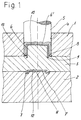
- the injection molding tool shown in detail in FIGS. 1 and 2 has a first mold plate 1 and a second mold plate 2, between which an intermediate plate 3 is arranged.
- the mold plate 1 has — in the embodiment of the injection mold as a multiple tool — a plurality of openings 4, in each of which a mold punch 5 engages, which can be displaced in the axial direction.
- the mold plate 2 is arranged towards the injection unit (not shown further) and is equipped with corresponding injection channels (also not shown further) for feeding the plasticized plastic into the mold nests 6 and 7 formed between the two mold plates 1 and 2 and the intermediate plate 3.
- the mold cavity 6 is used to form one individual part 6 'and the mold cavity 7 is used to form the other individual part 7'.
- the present injection molding device thus serves for the production of two-part finished parts.
- Each mold cavity 6 and 7 is determined by partial contours, which for the mold cavity 6 in a corresponding arrangement on the side of the intermediate plate 3 (mold contours 9) facing the mold plate 1 and the mold stamp 5 (shape contours 10) and for the mold cavity 7 on the mold plate 2 facing side of the intermediate plate or - Disk 3 (shape contours 11) and the mold plate 2 (shape contours 12) are provided.
- the forming die 5 has an annular chamfer 8, in which, in the injection position, as shown in FIG. 1, a correspondingly configured annular collar 13 of the intermediate plate 3 engages.
- the intermediate plate 3 as shown schematically in FIG. 3, is designed to be rotationally symmetrical and the shape-forming contours 11 (and 10) and the openings 14 lie on a pitch circle, with a total of four openings 14 in the present case and a corresponding number of shape contours are provided.
- the intermediate plate 3 is rotatably supported and rotatable relative to the mold plates 1 and 2 by a division step, so that either the mold contours 10 and 11 or one of the openings 14 are correlated with the mold stamp 5.
- the process for producing multi-part molded parts using the injection molding process is as follows: In the injection position (FIG. 1), the intermediate disk 3 assumes the position shown in FIG. 3, in which the individual shape contours of the intermediate disk 3 and the two mold plates 1 and 2 form the mold nests 6 and 7, respectively.
- the individual parts 6 'and 7' are now produced by injecting the plastic into the mold cavities 6 and 7 in one shot, but separately from one another.
- opening the Tool lifts the mold plate 1 in the axial direction; after the axial lifting of the intermediate plate 3 by a certain amount, the intermediate plate 3 is rotated by the dividing step, so that the opening 14 of the intermediate plate 3 is now in a coaxial orientation to the die 5, as can be seen in FIG. 2.
- the two individual molded parts 6 'and 7' are now brought together axially and connected and assembled with one another in a positive and / or non-positive manner, so that the finished part consisting of the individual parts 6 'and 7' is formed. Due to the annular recess 8 and the correspondingly designed collar 13 in the region of the parting line between the individual parts 6 'and 7' an annular circumferential cavity 15 is formed, which is injected with plastic after the assembly of the two individual parts 6 'and 7', so that a Additional connection of the two individual parts 6 'and 7' is created and the finished part forms a tight hollow body through this tight connection.
Landscapes
- Engineering & Computer Science (AREA)
- Mechanical Engineering (AREA)
- Manufacturing & Machinery (AREA)
- Moulds For Moulding Plastics Or The Like (AREA)
- Injection Moulding Of Plastics Or The Like (AREA)
Applications Claiming Priority (2)
| Application Number | Priority Date | Filing Date | Title |
|---|---|---|---|
| DE4417979 | 1994-05-21 | ||
| DE19944417979 DE4417979C2 (de) | 1994-05-21 | 1994-05-21 | Spritzgießwerkzeug zum Herstellen mehrteiliger Spritzguß-Formteile |
Publications (2)
| Publication Number | Publication Date |
|---|---|
| EP0683031A2 true EP0683031A2 (fr) | 1995-11-22 |
| EP0683031A3 EP0683031A3 (fr) | 1996-09-11 |
Family
ID=6518769
Family Applications (1)
| Application Number | Title | Priority Date | Filing Date |
|---|---|---|---|
| EP95106902A Withdrawn EP0683031A3 (fr) | 1994-05-21 | 1995-05-08 | Procédé de fabrication d'objets en plusieurs parties moulés par injection et dispositif pour la mise en oeuvre du procédé. |
Country Status (2)
| Country | Link |
|---|---|
| EP (1) | EP0683031A3 (fr) |
| DE (1) | DE4417979C2 (fr) |
Cited By (6)
| Publication number | Priority date | Publication date | Assignee | Title |
|---|---|---|---|---|
| FR2785915A1 (fr) * | 1998-11-17 | 2000-05-19 | Seb Sa | Procede d'obtention d'un reservoir d'eau en deux parties et reservoir selon ce procede |
| EP1166999A1 (fr) * | 2000-06-21 | 2002-01-02 | Ask Industries S.p.A. | Procédé pour l'assembage automatique et centré de pieces moulées |
| EP1484162A1 (fr) * | 2003-06-04 | 2004-12-08 | Weener Plastik GmbH & Co. KG | Procédé de fabrication d'un corps en matière plastique et récipient |
| US7241413B2 (en) | 2000-02-09 | 2007-07-10 | Trisa Holding Ag | Method for producing a hollow handle for a teeth cleaning device |
| US8826756B2 (en) | 2003-08-08 | 2014-09-09 | Brose Fahrzeugteile Gmbh & Co. Kg, Coburg | Adjustable mechanism for a motor vehicle |
| DE102014203979A1 (de) | 2014-03-05 | 2015-09-10 | Johnson Controls Gmbh | Verfahren und Vorrichtung zur Herstellung eines ausgeschäumten Hohlkörperspritzgusselementes |
Families Citing this family (9)
| Publication number | Priority date | Publication date | Assignee | Title |
|---|---|---|---|---|
| DE19727786C2 (de) * | 1997-06-30 | 2000-01-20 | Siegfried Hofmann Gmbh Werkzeu | Verfahren und Werkzeug zum Spritzgießen von Gegenständen |
| JP3368203B2 (ja) | 1998-06-02 | 2003-01-20 | ジー・ピー・ダイキョー株式会社 | 合成樹脂製中空体の製造方法及びその装置 |
| US6026852A (en) * | 1998-06-08 | 2000-02-22 | Blue Water Plastics, Inc. | Pressure relief valve and method of manufacturing the same |
| US6210619B1 (en) * | 1998-10-19 | 2001-04-03 | Ford Motor Company | Method for manufacturing a two-piece plastic assembly |
| DE20017737U1 (de) | 2000-10-16 | 2000-12-21 | Braun Formenbau GmbH, 79353 Bahlingen | Etagenwerkzeug zum Spritzgießen von Kunststoffteilen |
| DE10211663B4 (de) * | 2002-03-15 | 2011-02-10 | Johnson Controls Interiors Gmbh & Co. Kg | Verfahren zur Herstellung eines aus zwei einstückig miteinander verbundenen Segmenten bestehenden Formteils, insbesondere für einen Fahrzeuginnenraum, sowie nach diesem Verfahren hergestelltes Formteil |
| DE102008044694A1 (de) * | 2008-08-28 | 2010-03-04 | Hella Kgaa Hueck & Co. | Verfahren und Vorrichtung zur Herstellung einer Leuchtenbaueinheit |
| DE102014212300B4 (de) | 2014-05-08 | 2019-08-08 | FKT Formenbau und Kunststofftechnik GmbH | Verfahren zum Spritzgießen von mehrdimensionalen Gegenständen sowie Antriebsmodul für ein Spritzgusswerkzeug |
| JP6451603B2 (ja) * | 2015-11-18 | 2019-01-16 | 株式会社デンソー | 中空品の製造方法 |
Family Cites Families (7)
| Publication number | Priority date | Publication date | Assignee | Title |
|---|---|---|---|---|
| DE2501291A1 (de) * | 1975-01-15 | 1976-07-22 | Roehm Gmbh | Verfahren zur herstellung von hohlkoerpern nach dem spritzgiessverfahren |
| JPS59165632A (ja) * | 1983-03-10 | 1984-09-18 | Japan Steel Works Ltd:The | 中空品の射出成形方法及び装置 |
| JPS61193815A (ja) * | 1985-02-22 | 1986-08-28 | Hisanori Hatsutori | 合成樹脂中空成形体の製造方法 |
| GB2172837A (en) * | 1985-03-30 | 1986-10-01 | Mckecknie Brothers Plc | Injection moulding composite bodies |
| JPS6287315A (ja) * | 1985-10-15 | 1987-04-21 | Japan Steel Works Ltd:The | 中空成形品の成形方法及びそれに用いられる金型 |
| IT1206351B (it) * | 1986-11-06 | 1989-04-14 | Ferri Alberto Artuso Fedelia | Procedimento per la formazione di oggetti cavi in elastomero, ad iniezione e vulcanizzazione, con stampi ad elevata aderenza. |
| US5221538A (en) * | 1990-08-06 | 1993-06-22 | Japan Steel Works, Ltd. | Rotational injection molding machine having a plurality of combinations of male and female dies |
-
1994
- 1994-05-21 DE DE19944417979 patent/DE4417979C2/de not_active Expired - Lifetime
-
1995
- 1995-05-08 EP EP95106902A patent/EP0683031A3/fr not_active Withdrawn
Cited By (10)
| Publication number | Priority date | Publication date | Assignee | Title |
|---|---|---|---|---|
| FR2785915A1 (fr) * | 1998-11-17 | 2000-05-19 | Seb Sa | Procede d'obtention d'un reservoir d'eau en deux parties et reservoir selon ce procede |
| WO2000029203A1 (fr) * | 1998-11-17 | 2000-05-25 | Rowenta Werke Gmbh | Procede d'obtention d'un reservoir d'eau en deux parties et reservoir selon ce procede |
| US6425198B2 (en) | 1998-11-17 | 2002-07-30 | Rowenta Werke Gmbh | Method for making a two part reservoir and resulting reservoir |
| US7241413B2 (en) | 2000-02-09 | 2007-07-10 | Trisa Holding Ag | Method for producing a hollow handle for a teeth cleaning device |
| EP1166999A1 (fr) * | 2000-06-21 | 2002-01-02 | Ask Industries S.p.A. | Procédé pour l'assembage automatique et centré de pieces moulées |
| EP1484162A1 (fr) * | 2003-06-04 | 2004-12-08 | Weener Plastik GmbH & Co. KG | Procédé de fabrication d'un corps en matière plastique et récipient |
| US8826756B2 (en) | 2003-08-08 | 2014-09-09 | Brose Fahrzeugteile Gmbh & Co. Kg, Coburg | Adjustable mechanism for a motor vehicle |
| US9517589B2 (en) | 2003-08-08 | 2016-12-13 | Brose Fahrzeugteile Gmbh & Co. Kg, Coburg | Method for mounting adjustable mechanism for motor vehicle |
| EP1658451B2 (fr) † | 2003-08-08 | 2017-03-01 | Brose Fahrzeugteile GmbH & Co. Kommanditgesellschaft, Coburg | Mécanisme de réglage pour véhicule automobile et procédé de fabrication de cette mécanisme |
| DE102014203979A1 (de) | 2014-03-05 | 2015-09-10 | Johnson Controls Gmbh | Verfahren und Vorrichtung zur Herstellung eines ausgeschäumten Hohlkörperspritzgusselementes |
Also Published As
| Publication number | Publication date |
|---|---|
| DE4417979C2 (de) | 1996-10-02 |
| DE4417979A1 (de) | 1995-11-23 |
| EP0683031A3 (fr) | 1996-09-11 |
Similar Documents
| Publication | Publication Date | Title |
|---|---|---|
| DE4126041C2 (de) | Spritzgießform mit verdrehbaren, zu verschiedenen Kombinationen zusammenstellbaren Patrizen- und Matrizen-Einzelformen | |
| EP0683031A2 (fr) | Procédé de fabrication d'objets en plusieurs parties moulés par injection et dispositif pour la mise en oeuvre du procédé | |
| EP1226916A1 (fr) | Dispositif et procédé pour la production d'objects en matière plastic | |
| EP2726265B1 (fr) | Dispositif et procédé de production de pièces moulées par injection comprenant différents composants | |
| EP0946347A1 (fr) | Procede et dispositif de production d'un element en matiere plastique multicouche | |
| EP0504571A2 (fr) | Moule pour le moulage par injection de corps de brosse à plusieurs composants | |
| EP0147571A2 (fr) | Outil pour mouler par injection des objets en matière plastique | |
| DE2055261B2 (de) | Kunststoff-spritzgiessmaschine zum herstellen von aus zwei verschiedenen kunststoffmassen bestehenden spritzgussteilen | |
| DE102007026385A1 (de) | Entlüftungsvorrichtung für ein Kraftfahrzeug sowie Formwerkzeug und Verfahren zur Herstellung der Entlüftungsvorrichtung | |
| EP3093115B1 (fr) | Dispositif de réception et procédé d'injection | |
| EP2585276A1 (fr) | Procédé et dispositif de production d'une pièce structurale | |
| DE102007051701A1 (de) | Vorrichtung und Verfahren zur Herstellung mehrkomponentiger Kunststoff-Formteile | |
| DE4241409C2 (de) | Verfahren sowie Vorrichtung zum Herstellen eines Bauteils durch Spritzen wenigstens zweier Elemente aus Kunststoff und durch Zusammenfügen dieser Elemente nach dem Spritzen | |
| EP3482905B1 (fr) | Moule ainsi que procédé de moulage d'un composant | |
| DE2927642A1 (de) | Uebertragungseinrichtung fuer vorformlinge und fertigerzeugnisse fuer kunststoffspritzblaseinrichtungen | |
| EP0710534B1 (fr) | Procédé et dispositif pour fabriquer des corps de brosse à partir d'au moins deux composants de matière plastique | |
| EP0419953A2 (fr) | Dispositif pour le moulage par injection en deux couches | |
| DE19504332A1 (de) | Verfahren zur gleichzeitigen Herstellung und Montage von Einzelteilen im Spritzguß | |
| EP1338399A1 (fr) | Objet moulé par injection de plusieurs matières, et dispositif et procédé pour sa fabrication | |
| EP0139841B1 (fr) | Procédé et dispositif pour fabriquer un corps creux en matériel thermoplastique par procédé de soufflage | |
| EP1046486B1 (fr) | Outil de moulage pour fabriquer plusieurs pièces montées par moulage par injection | |
| DE3102219C2 (fr) | ||
| DE102021129386A1 (de) | Mischkopf und Herstellungsverfahren für Mischkopf | |
| DE3906914A1 (de) | Vorrichtung zum press-spritzen von presslingen insbesondere o-ringen | |
| DE202016104347U1 (de) | Spritzgießmaschine zum Herstellen eines Mehrkomponenten-Kunststoffteils |
Legal Events
| Date | Code | Title | Description |
|---|---|---|---|
| PUAI | Public reference made under article 153(3) epc to a published international application that has entered the european phase |
Free format text: ORIGINAL CODE: 0009012 |
|
| AK | Designated contracting states |
Kind code of ref document: A2 Designated state(s): AT CH DE ES FR GB IT LI PT SE |
|
| PUAL | Search report despatched |
Free format text: ORIGINAL CODE: 0009013 |
|
| AK | Designated contracting states |
Kind code of ref document: A3 Designated state(s): AT CH DE ES FR GB IT LI PT SE |
|
| STAA | Information on the status of an ep patent application or granted ep patent |
Free format text: STATUS: THE APPLICATION IS DEEMED TO BE WITHDRAWN |
|
| 18D | Application deemed to be withdrawn |
Effective date: 19970312 |