EP0683047A1 - Dispositif pour fixer une plaque d'impression - Google Patents
Dispositif pour fixer une plaque d'impression Download PDFInfo
- Publication number
- EP0683047A1 EP0683047A1 EP95103229A EP95103229A EP0683047A1 EP 0683047 A1 EP0683047 A1 EP 0683047A1 EP 95103229 A EP95103229 A EP 95103229A EP 95103229 A EP95103229 A EP 95103229A EP 0683047 A1 EP0683047 A1 EP 0683047A1
- Authority
- EP
- European Patent Office
- Prior art keywords
- plate cylinder
- strip
- clamping
- terminal
- strips
- Prior art date
- Legal status (The legal status is an assumption and is not a legal conclusion. Google has not performed a legal analysis and makes no representation as to the accuracy of the status listed.)
- Granted
Links
- 238000007639 printing Methods 0.000 title claims description 16
- 230000008878 coupling Effects 0.000 claims abstract description 7
- 238000010168 coupling process Methods 0.000 claims abstract description 7
- 238000005859 coupling reaction Methods 0.000 claims abstract description 7
- 238000012937 correction Methods 0.000 claims description 3
- 238000007645 offset printing Methods 0.000 claims description 2
- 230000002093 peripheral effect Effects 0.000 abstract 1
- 102000001999 Transcription Factor Pit-1 Human genes 0.000 description 8
- 108010040742 Transcription Factor Pit-1 Proteins 0.000 description 8
- 238000005452 bending Methods 0.000 description 2
- 229910000639 Spring steel Inorganic materials 0.000 description 1
- 238000004873 anchoring Methods 0.000 description 1
- 230000006835 compression Effects 0.000 description 1
- 238000007906 compression Methods 0.000 description 1
- 238000011161 development Methods 0.000 description 1
- 230000018109 developmental process Effects 0.000 description 1
- 238000004519 manufacturing process Methods 0.000 description 1
- 230000000149 penetrating effect Effects 0.000 description 1
- 230000036316 preload Effects 0.000 description 1
- 239000000725 suspension Substances 0.000 description 1
Images


Classifications
-
- B—PERFORMING OPERATIONS; TRANSPORTING
- B41—PRINTING; LINING MACHINES; TYPEWRITERS; STAMPS
- B41F—PRINTING MACHINES OR PRESSES
- B41F27/00—Devices for attaching printing elements or formes to supports
- B41F27/12—Devices for attaching printing elements or formes to supports for attaching flexible printing formes
- B41F27/1218—Devices for attaching printing elements or formes to supports for attaching flexible printing formes comprising printing plate tensioning devices
- B41F27/1225—Devices for attaching printing elements or formes to supports for attaching flexible printing formes comprising printing plate tensioning devices moving in the printing plate end substantially rectilinearly
- B41F27/1231—Devices for attaching printing elements or formes to supports for attaching flexible printing formes comprising printing plate tensioning devices moving in the printing plate end substantially rectilinearly by translatory motion substantially tangential to support surface
Definitions
- the invention relates to a device for fastening printing plates according to the preamble of claim 1.
- the printing plates are usually clamped on a plate cylinder between a clamping bar which is fixed with respect to the plate cylinder and a clamping bar which is movably mounted relative to the latter.
- the mechanism for applying the clamping force between the movable and the fixed terminal block can consist, for example, of an eccentric shaft.
- Fastening devices for printing plates in which the clamping force is applied by spring elements, are known from JP 3-252A and DE 4 129 831 A1.
- an upper terminal strip is movably mounted relative to a lower terminal strip which is fixed to the cylinder by means of a degree guide, the upper terminal strip being pressed against the lower terminal strip by compression springs attached in the lower, fixed terminal strip.
- An eccentric shaft is provided for introducing a new pressure plate or for removing a used pressure plate, by means of which the upper clamping bar is lifted from the lower clamping bar against the force of the spring elements.
- the upper clamping bar is mounted in a cylinder-fixed manner and the lower clamping bar is mounted so that it can be pressed against it under spring preload.
- this fastening device is opened by restoring elements acting counter to the spring force.
- a disadvantage of these previously known fastening devices for printing plates is, on the one hand, the structural outlay in order to mount one terminal strip so that it can move relative to the other. Furthermore, in order to ensure a sufficient fastening force for the printing plate, a plurality of spring elements must be accommodated in corresponding recesses across the format width of the terminal strip and plate cylinder, which in turn represents a manufacturing outlay.
- DE 3 806 526 C2 discloses a mounting of a tensioning rail with respect to the plate cylinder formed from leaf springs.
- the leaf spring is not used to attach (clamp) a pressure plate.
- the object of the present invention is therefore to develop a device for fastening printing plates in accordance with the preamble of claim 1 in such a way that the disadvantages mentioned are avoided.
- the movable clamping bar is supported by at least one leaf spring element with respect to the cylinder-fixed clamping bar, this leaf spring element being set in such a way that the holding force for the pressure plate is applied between the movable and the fixed clamping bar.
- the leaf spring elements provided thus represent the bearing and the spring elements for the terminal strips.
- the one terminal strip is mounted as a coupling in the manner of a coupling quadrilateral with the two leaf springs as rockers relative to the other clamping strip as a frame.
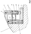
- FIG. 1 shows a part of a plate cylinder 1 with a pit 2 mounted therein.
- a lower clamping strip 3 is attached, for example, in one piece and extends across the format width of the plate cylinder 1.
- the clamped end of the leaf spring 5 facing surfaces of the terminal block 3 and the bar 6 are made in a slope, so that the leaf spring 5 is held by a curvature of a bias when its other end on the terminal block 3rd lies on.
- the movable terminal block 4 is formed in this embodiment by the pivotable end of the leaf spring 5.
- Pressure plate is thus held between the surfaces of the movable clamping bar 4 formed by the pivotable end of the leaf spring 5 and the lower clamping bar 3 by the force of the preloaded leaf spring 5.
- an actuating device 8 is provided between the leaf spring 5 and the clamping strip 3, which in this exemplary embodiment is an eccentric shaft or a shaft a flat is formed.
- actuating elements 8 can also be provided here.
- this shaft is, as shown in FIG. 1, embedded in a groove-shaped groove in the terminal strip 3 below the leaf spring 5.
- the fastening device for printing plates shown in FIG. 1, consisting of the clamping strip 3 with the leaf spring 5 clamped therein, can either be made in one piece extending over the format width of the plate cylinder 1 or else it can be divided one or more times. Furthermore, it is possible that, for example, the terminal strip 3 extends in one piece over the format width and a plurality of divided leaf springs 5 are attached.
- the actuating element 8 When the actuating element 8 is designed to release the terminal strip 4 from the terminal strip 3 by bending the leaf spring 5 as an eccentric shaft or a shaft with a flattening, as shown in FIG. 1, this shaft is in a trough-shaped groove in the terminal strip 3 below the leaf spring 5 let in.
- the terminal strip 3 is designed here as an angle rail with two additional strips 3.1, 3.2.
- a pair of leaf springs 5 are clamped between two additional strips 3.1 and 3.2 via fastening screws 7 spaced axially apart from one another.
- the upper terminal block 4 is designed as an angle rail, at the end facing the bottom of the pit 2 via two further strips 4.1, 4.2 and axially spaced fastening screws 7, the ends of the pair of leaf springs 5 are clamped.
- the upper terminal block 4 is thus movably mounted relative to the lower terminal block 3 via the pair of leaf springs 5 in the manner of a parallel suspension or a parallel rocker (with the terminal block 4 as a coupling).
- an actuating element 8 is attached which is supported on the terminal strip 3, which is shown in FIG. 2 as an eccentric shaft or as a shaft with a flattened portion.
- the storage of the terminal block 4 via the leaf springs 5 with respect to the terminal block 3 is here placed under tension so that between the upper surface of the bar 3.2 and the opposite surface of the terminal block 4, the force necessary to hold a pressure plate is generated.
- the actuating element 8 the terminal strip 4 can be lifted off the terminal strip 3 or the strip 3.2 against the pretension of the leaf springs 5. A gap thus arises between the terminal strip 4 and the upper surface of the strip 3.2, so that a clamped pressure plate can be removed or a new pressure plate can be inserted.
- the actuating element 8 guides the upper clamping strip 4, which is guided over the prestressed leaf springs 5, predominantly in a straight vertical manner.
- the additional bending of the leaf springs 5 results in only a slight horizontal movement.
- the leaf springs 5 run at an angle to one another in order to achieve an additional pivoting movement of the terminal strip 4 when opening.
- the upper terminal block 4 is also supported by a pair of leaf springs 5 with respect to the lower terminal block 3.
- the terminal strip 3 is essentially designed as a U-profile.
- One end of a leaf spring 5 is clamped in each case by one leg of the U-profile-shaped clamping strip 3 relative to one another by means of strips 3.1, 3.2 and fastening screws 7 spaced apart in the axial direction of the plate cylinder 1.
- the ends of the leaf springs 5 are attached to the underside of the upper terminal block 4 via two strips 4.1, 4.2 and further fastening screws 7.
- dashed screws 7 are indicated by dashed lines, which are axially offset in the axial direction of the plate cylinder 1 with respect to the fastening screws 7 penetrating the strips 4.1 and 4.2 from below.
- the leaf springs 5 result in an anti-parallel rocker with the terminal block 4 as a coupling element.
- Fig. 3 shows the fastening device according to the invention for printing plates in the so-called clamping position.
- a pressure plate is clamped here by the prestressing of the leaf springs 5 between the underside of the terminal strip 4 and the top of the strip 3.1 connected to the terminal strip 3.
- the shaft of the actuating element 8 which is symbolically provided here as an eccentric shaft or as a shaft with a flattened portion, the upper terminal strip 4 is pressed upwards over the strips 4.1, 4.2 against the bias of the leaf springs 5 with a simultaneous slight pivoting movement in the clockwise direction. There is thus a relatively large gap for inserting a new pressure plate between the underside of the upper terminal strip 4 and the correspondingly opposite surface of the strip 3.1.
- the fastening device shown in FIGS. 3 and 4 is preferably suitable as a tensioning device for the printing end of the plate cylinder 1.
- the lower clamping bar 3 is preferably movably mounted parallel to the bottom of the pit 2 of the plate cylinder 1 (guide means not shown).
- a clamping device 9 is arranged between a wall of the pit 2 and the opposite surface of the terminal strip 3 or the bar 3.1, by means of which the terminal strip 3 can be moved in the direction of the center of the pit 2. As a result, a clamped pressure plate is stretched around the outer circumference of the plate cylinder 1.
- the holding force to be provided is to set the pressure plate between the terminal strips 3 and 4 by a corresponding preloading of the leaf springs 5 to be provided according to the invention.
- the leaf springs 5 can preferably be made of spring steel with a predetermined profile or curvature.
- a plurality of leaf springs 5 can also be arranged at an angle to one another.
- the fastening device according to the invention for printing plates consisting of the terminal strips 3 and 4 and their connection via the leaf springs 5, can be formed in one part but also in several parts over the format width of the plate cylinder 1.
Landscapes
- Supply, Installation And Extraction Of Printed Sheets Or Plates (AREA)
- Connection Of Plates (AREA)
- Character Spaces And Line Spaces In Printers (AREA)
Applications Claiming Priority (2)
| Application Number | Priority Date | Filing Date | Title |
|---|---|---|---|
| DE4410385 | 1994-03-25 | ||
| DE4410385A DE4410385C2 (de) | 1994-03-25 | 1994-03-25 | Vorrichtung zum Befestigen von Druckplatten |
Publications (2)
| Publication Number | Publication Date |
|---|---|
| EP0683047A1 true EP0683047A1 (fr) | 1995-11-22 |
| EP0683047B1 EP0683047B1 (fr) | 1997-07-23 |
Family
ID=6513840
Family Applications (1)
| Application Number | Title | Priority Date | Filing Date |
|---|---|---|---|
| EP95103229A Expired - Lifetime EP0683047B1 (fr) | 1994-03-25 | 1995-03-07 | Dispositif pour fixer une plaque d'impression |
Country Status (3)
| Country | Link |
|---|---|
| EP (1) | EP0683047B1 (fr) |
| AT (1) | ATE155740T1 (fr) |
| DE (2) | DE4410385C2 (fr) |
Cited By (1)
| Publication number | Priority date | Publication date | Assignee | Title |
|---|---|---|---|---|
| DE102009027508A1 (de) * | 2009-07-07 | 2011-01-20 | Manroland Ag | Greifer einer bogenhandhabenden Maschine |
Families Citing this family (2)
| Publication number | Priority date | Publication date | Assignee | Title |
|---|---|---|---|---|
| DE10024087C2 (de) * | 2000-05-18 | 2002-05-08 | Torald Rohloff | Vorrichtung zum Befestigen einer Druckplatte auf einem Zylinder einer Rotationsdruckmaschine |
| DE102012207106B4 (de) * | 2012-04-27 | 2015-04-02 | Koenig & Bauer Aktiengesellschaft | Plattenzylinder |
Citations (4)
| Publication number | Priority date | Publication date | Assignee | Title |
|---|---|---|---|---|
| US2378478A (en) * | 1943-02-18 | 1945-06-19 | Goss Printing Press Co Ltd | Printing press gripper mechanism |
| DE1761308A1 (de) * | 1968-05-02 | 1971-05-13 | Polygraph Leipzig | Verfahren und Vorrichtung zum Klemmen von Materialbogen |
| DD237815A1 (de) * | 1985-05-31 | 1986-07-30 | Polygraph Leipzig | Vorrichtung zur befestigung einer biegsamen druckplatte |
| EP0276736A2 (fr) * | 1987-01-24 | 1988-08-03 | BASF Aktiengesellschaft | Dispositif de tension de plaques d'impression |
Family Cites Families (7)
| Publication number | Priority date | Publication date | Assignee | Title |
|---|---|---|---|---|
| DD261770A1 (de) * | 1987-07-02 | 1988-11-09 | Polygraph Leipzig | Vorrichtung zum befestigen einer biegsamen druckplatte |
| DD261769A1 (de) * | 1987-07-02 | 1988-11-09 | Polygraph Leipzig | Vorrichtung zum befestigen einer biegsamen druckplatte |
| DE3806526A1 (de) * | 1988-03-01 | 1989-09-14 | Heidelberger Druckmasch Ag | Vorrichtung zum spannen von biegsamen druckplatten am plattenzylinder von rotationsdruckmaschinen |
| DE3900818C1 (fr) * | 1989-01-13 | 1990-05-10 | Heidelberger Druckmaschinen Ag, 6900 Heidelberg, De | |
| JPH0649369B2 (ja) * | 1989-05-29 | 1994-06-29 | アキヤマ印刷機製造株式会社 | 枚葉印刷機の版締め装置 |
| DE4129831C3 (de) * | 1990-12-21 | 1998-08-13 | Heidelberger Druckmasch Ag | Schnellklemmvorrichtung |
| DE4315906A1 (de) * | 1993-05-12 | 1994-11-17 | Philips Patentverwaltung | Stromversorgungsschaltung |
-
1994
- 1994-03-25 DE DE4410385A patent/DE4410385C2/de not_active Expired - Fee Related
-
1995
- 1995-03-07 EP EP95103229A patent/EP0683047B1/fr not_active Expired - Lifetime
- 1995-03-07 AT AT95103229T patent/ATE155740T1/de not_active IP Right Cessation
- 1995-03-07 DE DE59500409T patent/DE59500409D1/de not_active Expired - Fee Related
Patent Citations (4)
| Publication number | Priority date | Publication date | Assignee | Title |
|---|---|---|---|---|
| US2378478A (en) * | 1943-02-18 | 1945-06-19 | Goss Printing Press Co Ltd | Printing press gripper mechanism |
| DE1761308A1 (de) * | 1968-05-02 | 1971-05-13 | Polygraph Leipzig | Verfahren und Vorrichtung zum Klemmen von Materialbogen |
| DD237815A1 (de) * | 1985-05-31 | 1986-07-30 | Polygraph Leipzig | Vorrichtung zur befestigung einer biegsamen druckplatte |
| EP0276736A2 (fr) * | 1987-01-24 | 1988-08-03 | BASF Aktiengesellschaft | Dispositif de tension de plaques d'impression |
Cited By (1)
| Publication number | Priority date | Publication date | Assignee | Title |
|---|---|---|---|---|
| DE102009027508A1 (de) * | 2009-07-07 | 2011-01-20 | Manroland Ag | Greifer einer bogenhandhabenden Maschine |
Also Published As
| Publication number | Publication date |
|---|---|
| EP0683047B1 (fr) | 1997-07-23 |
| DE4410385C2 (de) | 1997-07-17 |
| DE59500409D1 (de) | 1997-08-28 |
| DE4410385A1 (de) | 1995-09-28 |
| ATE155740T1 (de) | 1997-08-15 |
Similar Documents
| Publication | Publication Date | Title |
|---|---|---|
| DE69601121T2 (de) | Schnellspannvorrichtung für wenigstens ein Werkzeug einer Werkzeugmaschine | |
| EP0238804B1 (fr) | Dispositif de fixation des clichés souples sur les cylindres de clichés dans les rotatives | |
| EP1278636B1 (fr) | Dispositif pour fixer une plaque souple | |
| DE3428668A1 (de) | Umfuehrtrommel fuer bogendruckmaschinen, insbesondere kartonmaschinen | |
| EP0596337B1 (fr) | Dispositif pour placer en répérage des plaques d'impression sur des cylindres de plaque des machines | |
| DE4214168A1 (de) | Vorrichtung zum aufspannen von druckplatten auf dem plattenzylinder von druckmaschinen, insbesondere bogenoffsetdruckmaschinen | |
| DE3620883C2 (fr) | ||
| EP0739726A2 (fr) | Dispositif pour tendre une plaque d'impression sur le cylindre porte-plaque d'une machine d'impression rotative | |
| DE102007002785A1 (de) | Rotationssymmetrischer Körper mit einer Spannvorrichtung zur Befestigung von plattenförmigen Gegenständen | |
| EP0683047B1 (fr) | Dispositif pour fixer une plaque d'impression | |
| DE10009667B4 (de) | Spanneinrichtung zum Aufspannen von Druckformen | |
| EP1497126B1 (fr) | Cylindre d'une machine a imprimer rotative avec un dispositif de fixation d'au moins un habillage sur ce cylindre | |
| WO1997047813A1 (fr) | Dispositif de commutation de lames d'aiguille | |
| EP1182036B1 (fr) | Dispositif pour réglage d'au moins un élément de repérage dans une machine d'impression et procédé correspondant | |
| EP0483535B1 (fr) | Dispositif de serrage pour fixer de fins revêtements sur des cylindres transportant des feuilles dans des rotatives d'impression pour feuilles | |
| DE2720673B2 (de) | Vorrichtung zum ungleichförmigen Spannen eines Gummituches in einer Offsetdruckmaschine | |
| EP0755785A1 (fr) | Dispositif de fixation d'une plaque avec réduction de la zÔne sans pression | |
| DE19816512A1 (de) | Bogengreifer in einer Bogenrotationsdruckmaschine | |
| EP0734861B1 (fr) | Procédé et appareil pour le montage de plaques d'impression flexibles | |
| DE19611124B4 (de) | Bogenübertragungseinrichtung einer Bogenrotationsdruckmaschine | |
| EP0875378B2 (fr) | Dispositif de serrage | |
| DE4314436C2 (de) | Spannschiene für den Plattenzylinder einer Druckmaschine, insbesondere Bogenoffsetdruckmaschine | |
| EP3546215B1 (fr) | Dispositif pour fixer des plaques d'impression sur un cylindre porte-plaque | |
| DE3521590C1 (de) | Bogenglaetteinrichtung fuer die Greiferkante eines Bogens an der Bogenanlage einer Bogenrotationsdruckmaschine | |
| DE4134309C2 (de) | Einrichtung zum Schnellaufspannen von Druckplatten |
Legal Events
| Date | Code | Title | Description |
|---|---|---|---|
| PUAI | Public reference made under article 153(3) epc to a published international application that has entered the european phase |
Free format text: ORIGINAL CODE: 0009012 |
|
| 17P | Request for examination filed |
Effective date: 19950322 |
|
| AK | Designated contracting states |
Kind code of ref document: A1 Designated state(s): AT CH DE FR GB LI |
|
| GRAG | Despatch of communication of intention to grant |
Free format text: ORIGINAL CODE: EPIDOS AGRA |
|
| GRAH | Despatch of communication of intention to grant a patent |
Free format text: ORIGINAL CODE: EPIDOS IGRA |
|
| 17Q | First examination report despatched |
Effective date: 19961213 |
|
| GRAH | Despatch of communication of intention to grant a patent |
Free format text: ORIGINAL CODE: EPIDOS IGRA |
|
| GRAA | (expected) grant |
Free format text: ORIGINAL CODE: 0009210 |
|
| AK | Designated contracting states |
Kind code of ref document: B1 Designated state(s): AT CH DE FR GB LI |
|
| REF | Corresponds to: |
Ref document number: 155740 Country of ref document: AT Date of ref document: 19970815 Kind code of ref document: T |
|
| REG | Reference to a national code |
Ref country code: CH Ref legal event code: NV Representative=s name: E. BLUM & CO. PATENTANWAELTE Ref country code: CH Ref legal event code: EP |
|
| REF | Corresponds to: |
Ref document number: 59500409 Country of ref document: DE Date of ref document: 19970828 |
|
| ET | Fr: translation filed | ||
| GBT | Gb: translation of ep patent filed (gb section 77(6)(a)/1977) |
Effective date: 19971029 |
|
| PLBE | No opposition filed within time limit |
Free format text: ORIGINAL CODE: 0009261 |
|
| STAA | Information on the status of an ep patent application or granted ep patent |
Free format text: STATUS: NO OPPOSITION FILED WITHIN TIME LIMIT |
|
| 26N | No opposition filed | ||
| PGFP | Annual fee paid to national office [announced via postgrant information from national office to epo] |
Ref country code: GB Payment date: 20000211 Year of fee payment: 6 |
|
| PGFP | Annual fee paid to national office [announced via postgrant information from national office to epo] |
Ref country code: CH Payment date: 20000221 Year of fee payment: 6 |
|
| PGFP | Annual fee paid to national office [announced via postgrant information from national office to epo] |
Ref country code: FR Payment date: 20000224 Year of fee payment: 6 |
|
| PGFP | Annual fee paid to national office [announced via postgrant information from national office to epo] |
Ref country code: AT Payment date: 20010226 Year of fee payment: 7 |
|
| PG25 | Lapsed in a contracting state [announced via postgrant information from national office to epo] |
Ref country code: GB Free format text: LAPSE BECAUSE OF NON-PAYMENT OF DUE FEES Effective date: 20010307 |
|
| PG25 | Lapsed in a contracting state [announced via postgrant information from national office to epo] |
Ref country code: LI Free format text: LAPSE BECAUSE OF NON-PAYMENT OF DUE FEES Effective date: 20010331 Ref country code: CH Free format text: LAPSE BECAUSE OF NON-PAYMENT OF DUE FEES Effective date: 20010331 |
|
| GBPC | Gb: european patent ceased through non-payment of renewal fee |
Effective date: 20010307 |
|
| REG | Reference to a national code |
Ref country code: CH Ref legal event code: PL |
|
| PG25 | Lapsed in a contracting state [announced via postgrant information from national office to epo] |
Ref country code: FR Free format text: LAPSE BECAUSE OF NON-PAYMENT OF DUE FEES Effective date: 20011130 |
|
| REG | Reference to a national code |
Ref country code: FR Ref legal event code: ST |
|
| PG25 | Lapsed in a contracting state [announced via postgrant information from national office to epo] |
Ref country code: AT Free format text: LAPSE BECAUSE OF NON-PAYMENT OF DUE FEES Effective date: 20020307 |
|
| PGFP | Annual fee paid to national office [announced via postgrant information from national office to epo] |
Ref country code: DE Payment date: 20080321 Year of fee payment: 14 |
|
| PG25 | Lapsed in a contracting state [announced via postgrant information from national office to epo] |
Ref country code: DE Free format text: LAPSE BECAUSE OF NON-PAYMENT OF DUE FEES Effective date: 20091001 |