EP0683064A1 - Fenêtre glissante pour véhicule - Google Patents
Fenêtre glissante pour véhicule Download PDFInfo
- Publication number
- EP0683064A1 EP0683064A1 EP95105078A EP95105078A EP0683064A1 EP 0683064 A1 EP0683064 A1 EP 0683064A1 EP 95105078 A EP95105078 A EP 95105078A EP 95105078 A EP95105078 A EP 95105078A EP 0683064 A1 EP0683064 A1 EP 0683064A1
- Authority
- EP
- European Patent Office
- Prior art keywords
- vehicle
- pane
- window according
- sliding
- sliding window
- Prior art date
- Legal status (The legal status is an assumption and is not a legal conclusion. Google has not performed a legal analysis and makes no representation as to the accuracy of the status listed.)
- Granted
Links
- 238000009423 ventilation Methods 0.000 description 9
- 238000006073 displacement reaction Methods 0.000 description 4
- 230000006978 adaptation Effects 0.000 description 1
- 239000000969 carrier Substances 0.000 description 1
- 230000002349 favourable effect Effects 0.000 description 1
- 239000011521 glass Substances 0.000 description 1
- 238000009434 installation Methods 0.000 description 1
- 230000005226 mechanical processes and functions Effects 0.000 description 1
- 230000004048 modification Effects 0.000 description 1
- 238000012986 modification Methods 0.000 description 1
Images


Classifications
-
- E—FIXED CONSTRUCTIONS
- E05—LOCKS; KEYS; WINDOW OR DOOR FITTINGS; SAFES
- E05D—HINGES OR SUSPENSION DEVICES FOR DOORS, WINDOWS OR WINGS
- E05D15/00—Suspension arrangements for wings
- E05D15/06—Suspension arrangements for wings for wings sliding horizontally more or less in their own plane
- E05D15/10—Suspension arrangements for wings for wings sliding horizontally more or less in their own plane movable out of one plane into a second parallel plane
- E05D15/1065—Suspension arrangements for wings for wings sliding horizontally more or less in their own plane movable out of one plane into a second parallel plane with transversely moving track
- E05D15/1081—Suspension arrangements for wings for wings sliding horizontally more or less in their own plane movable out of one plane into a second parallel plane with transversely moving track specially adapted for vehicles
-
- B—PERFORMING OPERATIONS; TRANSPORTING
- B60—VEHICLES IN GENERAL
- B60J—WINDOWS, WINDSCREENS, NON-FIXED ROOFS, DOORS, OR SIMILAR DEVICES FOR VEHICLES; REMOVABLE EXTERNAL PROTECTIVE COVERINGS SPECIALLY ADAPTED FOR VEHICLES
- B60J1/00—Windows; Windscreens; Accessories therefor
- B60J1/08—Windows; Windscreens; Accessories therefor arranged at vehicle sides
- B60J1/12—Windows; Windscreens; Accessories therefor arranged at vehicle sides adjustable
- B60J1/16—Windows; Windscreens; Accessories therefor arranged at vehicle sides adjustable slidable
-
- E—FIXED CONSTRUCTIONS
- E05—LOCKS; KEYS; WINDOW OR DOOR FITTINGS; SAFES
- E05D—HINGES OR SUSPENSION DEVICES FOR DOORS, WINDOWS OR WINGS
- E05D15/00—Suspension arrangements for wings
- E05D15/56—Suspension arrangements for wings with successive different movements
- E05D15/58—Suspension arrangements for wings with successive different movements with both swinging and sliding movements
-
- E—FIXED CONSTRUCTIONS
- E05—LOCKS; KEYS; WINDOW OR DOOR FITTINGS; SAFES
- E05D—HINGES OR SUSPENSION DEVICES FOR DOORS, WINDOWS OR WINGS
- E05D15/00—Suspension arrangements for wings
- E05D15/06—Suspension arrangements for wings for wings sliding horizontally more or less in their own plane
- E05D15/10—Suspension arrangements for wings for wings sliding horizontally more or less in their own plane movable out of one plane into a second parallel plane
- E05D15/1065—Suspension arrangements for wings for wings sliding horizontally more or less in their own plane movable out of one plane into a second parallel plane with transversely moving track
- E05D2015/1071—Suspension arrangements for wings for wings sliding horizontally more or less in their own plane movable out of one plane into a second parallel plane with transversely moving track the track being directly linked to the fixed frame, e.g. slidingly
- E05D2015/1078—Suspension arrangements for wings for wings sliding horizontally more or less in their own plane movable out of one plane into a second parallel plane with transversely moving track the track being directly linked to the fixed frame, e.g. slidingly swinging or rotating in a horizontal plane
-
- E—FIXED CONSTRUCTIONS
- E05—LOCKS; KEYS; WINDOW OR DOOR FITTINGS; SAFES
- E05D—HINGES OR SUSPENSION DEVICES FOR DOORS, WINDOWS OR WINGS
- E05D15/00—Suspension arrangements for wings
- E05D15/06—Suspension arrangements for wings for wings sliding horizontally more or less in their own plane
- E05D15/10—Suspension arrangements for wings for wings sliding horizontally more or less in their own plane movable out of one plane into a second parallel plane
- E05D15/1065—Suspension arrangements for wings for wings sliding horizontally more or less in their own plane movable out of one plane into a second parallel plane with transversely moving track
- E05D2015/1084—Suspension arrangements for wings for wings sliding horizontally more or less in their own plane movable out of one plane into a second parallel plane with transversely moving track the carriage being directly linked to the fixed frame, e.g. slidingly
-
- E—FIXED CONSTRUCTIONS
- E05—LOCKS; KEYS; WINDOW OR DOOR FITTINGS; SAFES
- E05Y—INDEXING SCHEME ASSOCIATED WITH SUBCLASSES E05D AND E05F, RELATING TO CONSTRUCTION ELEMENTS, ELECTRIC CONTROL, POWER SUPPLY, POWER SIGNAL OR TRANSMISSION, USER INTERFACES, MOUNTING OR COUPLING, DETAILS, ACCESSORIES, AUXILIARY OPERATIONS NOT OTHERWISE PROVIDED FOR, APPLICATION THEREOF
- E05Y2900/00—Application of doors, windows, wings or fittings thereof
- E05Y2900/50—Application of doors, windows, wings or fittings thereof for vehicles
- E05Y2900/53—Type of wing
- E05Y2900/55—Windows
Definitions
- the invention relates to a vehicle sliding window that can be inserted into an opening in side parts of a vehicle body and / or in the vehicle doors.
- opening windows In vehicles, opening windows are known which can be pivoted about a vertical axis or about an axis slightly inclined to the vertical. These windows are often used when it is a two-door car.
- the pivot axis of such opening windows lies in the area of the front edge of the windows when viewed in the forward direction of travel.
- a suitable opening fitting is provided on the opposite rear edge in the direction of travel in order to open the window to the outside.
- Windows are also known, the panes of which can be moved up and down in the vertical direction by means of a window lift drive. Such windows are designed for the doors of a vehicle. Windows of this type are usually used in multi-door passenger cars. In the case of passenger cars, these options have long been proven individually or in combination.
- the invention has for its object to provide a vehicle sliding window that offers the possibility in a structurally simple manner that either a ventilation slot such as the conventional opening windows or a ventilation opening can be formed, the level of the glass panes in the closed state approximately with the level of The outer skin of the body collapses in the window area.
- the vehicle sliding window has two panes which are in alignment in the closed position, that the front pane in the forward direction of travel can be tilted outwards about a vertical or slightly inclined axis relative to the vertical, and that the rear pane is displaceably arranged in the direction of travel so that in the open position it is laterally next to the inside of the issued front pane.
- the vehicle sliding window has two panes aligned in the closed position, that the front pane in the forward driving direction can be tilted outwards about a vertical or slightly inclined axis relative to the vertical, while the rear pane in the direction of travel is arranged to be stationary , and that the front disc is arranged so that it is at least partially laterally adjacent to the outside of the rear stationary disc in the open position.
- the vehicle sliding window is symmetrically or asymmetrically divided by the front and rear window in the closed position of the windows, with the asymmetrical division the length of the rear window in the forward direction is less than the front window.
- the lengths of the front pane to the rear pane are expediently in a ratio of approximately 2: 1. This results in particularly favorable installation conditions when the panes are next to each other. So that the vehicle sliding window can be used as a prefabricated unit in an opening in the body or the door, provision is made for the panes to be arranged on an outer frame which can be inserted into the opening of the body or the door.
- this frame is expediently made of profile bars of suitable cross-section, so that these bars can simultaneously be used as a guide for the displacement of the respective pane.
- the vertical profile spar, which is at the front in the direction of travel, of an additionally provided display frame is mounted in at least one bearing sleeve.
- the central longitudinal axis of this bearing sleeve then forms the pivot axis.
- a profiled rail which can preferably be moved back and forth on the lower horizontal profiled rail, is provided as the pane holder. This keeps the number of components to a minimum, so that the vehicle sliding window as a whole is very compact.
- a guide rail is expediently assigned to the upper and lower edge of the displaceable disk.
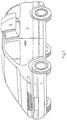
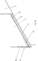
- FIGS. 2 and 3 A first embodiment of such a vehicle sliding window is shown in schematic form in FIGS. 2 and 3.
- a base frame 3, which is angular in cross section, is fixed to the side body parts.
- the vehicle sliding window 2 comprises a front pane 4 and a rear pane 5.
- the window is drawn in the closed position.
- the two disks 4, 5 are flush with one another in one plane.
- the forward direction of travel of the MPV 1 is indicated by the arrow A in FIG. 2.
- the front disc 4 is can be pivoted about a front vertical axis 6 and can thus be opened about this axis. This position is shown in the upper illustration.
- the pivoting movement is indicated in FIG. 2 by the double arrow B.
- the pane 4 On the side opposite to the axis of rotation 6, the pane 4 is equipped with an opening fitting designated as a whole as 7, which can be actuated from inside the vehicle.
- the opening fitting 7 can be moved on a guide rod 8.
- the opening fitting 7 is moved towards the axis 6.
- the rear disc 5 is also slidable on the guide rod 8. For this purpose, it is provided with bearing blocks 9 on the inside.
- the length of the front disc 4 is approximately twice as long as the length of the rear disc 5.
- the disc dimensions can of course also have a different relationship to one another. This makes it possible that after the front disk 4 has been raised, the rear disk 5 can be moved in the direction of the axis 6 to such an extent that the two rear ends of the disks 4, 5 stand side by side at the same height. This creates a ventilation opening that is the size of the rear disc 5 corresponds. It is evident from FIG. 2 that in this example only the front pane 4 can perform an opening movement in order to form a ventilation slot of relatively small width, while the rear pane 5 can be moved back and forth in the direction of arrow C.
- FIG. 3 shows a perspective view of the representation according to FIG. 2 with the vehicle sliding window 2 open in accordance with FIG. the upper representation in Figure 2.
- the guide rod 8 and the bearing blocks 9 are not shown in Fig. 3.
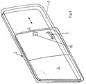
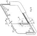
- FIGS. 4-8 show a second embodiment of the vehicle sliding window 2 according to the invention.
- This vehicle sliding window can also be divided asymmetrically in the shape 10, so that the length of the front pane 4 is twice or approximately twice as large as the length of the rear pane 5.
- the front pane 4 can be opened by means of an opening fitting 7.
- the rear window 5 is immovably attached to the body.
- the guide rod 8, which can also be part of a frame made of round rods, follows the opening movement of the front pane 4. There is one on the lower, possibly also on the upper edge of the pane 4 Guide rail 11 attached.
- the guide rail 11 is guided in a stationary guide rail holder 12.
- FIG. 4 shows the closed position of the two disks 4 and 5. In this position, the two disks are again in alignment with one another.
- the front pane 4 is flipped outwards, so that the two panes 4, 5 are at an angle to one another.
- a push handle 10 is in turn arranged to move the front disc 4 against the forward driving direction to the rear, thereby forming a ventilation opening.
- FIG. 5 shows the deployed position of the pane 4, while FIG. 6 shows the open position, in which the rear region of the front pane 4 is offset outwards relative to the rear pane 5.
- the rear disc 5 is gem in the embodiment. 4-8 stationary, i.e. it cannot be issued or postponed.
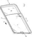
- Figures 7 u. 8 show the vehicle sliding window 2 of the above-described embodiment in a perspective view.
- Figure 7 shows the position shown
- Figure 8 shows the open position.
- the guide rod 8 is not shown.
- the direction of travel is indicated by arrow A. It can be seen from FIG. 8 that the size of the opening corresponds approximately to the size of the rear stationary disk 5.
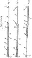
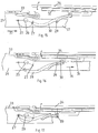
- FIGS. 9-11 show the complete front pane 4 with the associated fitting parts.
- the disc holder 13 consists of the two outer linear bushings 13 a and the intermediate receiving bush 13 b.
- FIG. 10 shows that the disc holder 13 is slidable on the guide rod 8.
- the guide rail holder 12 is arranged in the rear region of the front disk 4.
- FIG. 10 shows that the guide rail 11 is fixed on the edge of the front disk 4 in a manner that is not explained in detail.
- the guide rod 8 can be part of a frame, the front vertical spar being identified by the reference number 8 a.
- a bearing sleeve 14 is placed, which is attached to the base frame 3 (Fig. 4 to 6).
- the central axis 6 of the bearing sleeve 14 is the pivot axis for the opening movement of the front disk 4.
- FIG. 11 shows how the front pane 4 can be pushed laterally next to the rear stationary pane 5.
- the guide rail holder forms a stop for the sliding movement, since the disc holder 13 strikes against it.
- the respective discs 4 and 5 are closed in the reverse order.
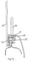
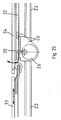
- FIGS. 12-18 show a further embodiment for a sliding and opening mechanism in detail. Since this is a variant which is preferably used in practice, it is explained in more detail below. Since the mechanical functions largely correspond to the other exemplary embodiments, what has been said here also applies to the other variants.
- the opening mechanism comprises a vertical axis 20, which is supported with its lower end in a mounting rail 21.
- the rear pane 33 which is in the direction of travel, is glued to the support rail 21 at several points or fastened in another suitable manner.
- the support rail 21 is placed on the lower horizontal beam 22 so that it can slide freely on this.
- the profile spar 22 simultaneously forms the lower part of the support frame 3.
- the upper corresponding profile spar of the frame 3 is designated by 23.
- the lateral vertical bars of the frame bear the reference numbers 24 and 25.
- the profile frame is screwed onto the edge of the body cut-out by means of screws 26 '.
- the vertical axis 20, which can be rotated at its upper end by means of a suitable handle, not shown, has at its lower end a nose 26, into which a driving pin 27 is inserted, which, when the axis 20 is rotated about its virtual axis, from the Nose 26 is taken eccentrically.
- the driving pin 27 engages the end of a link lever 28, which forms the actual opening lever and is coupled at its other end to a guide pin 29, which in turn is fastened to the mounting rail 21 and projects upwards so that it engages in a groove 30 engages, which is located in the rear part of the deployment lever 28.
- the end of the deployment lever 28 assigned to the guide pin 29 has a sliding shoe 31 which slides in a profile rail 32 to which the front opening window 34 is glued in the forward direction of travel.
- the slide shoe 31 is connected by a pin 35 to the associated end of the deployment lever 28.
- the deployment movement of the disc 34 is achieved by the axis 20 z. B. is rotated by hand about its virtual axis so that the driving lever 27 of the opening lever 28 and thus inevitably the slide shoe 31 attached to it is moved in the direction of arrow 36 (Fig. 16).
- the deployment lever 28 slides along the guide pin 29 with the inner walls of the groove 30 which is adapted by means of a suitable path curvature and raises the deployment disk 34.
- This opening position is shown in FIG. 15.
- the sliding window 33 in the direction of travel can be moved in the direction of arrow 37 (FIGS. 12, 15) using a handle (not shown) with its associated structural and functional parts 20, 21 and 24 to 29 and 31.
- the display disk 34 is continuously shown.
- FIG. 18 shows an embodiment for an opening mechanism in which, instead of the opening lever 28 in FIGS. 12-17, a modified opening lever 38 is provided, which with its end facing the opening disk 34 is articulated on a slide shoe 39 which has a groove 30 ' in which a pin 41 slides, which has the function of the guide pin 29 from FIG. 13. Otherwise, the movement sequences between the variant according to FIG. 13 and the embodiment according to FIG. 18 are corresponding. Insofar as the same parts are used, the reference symbols correspond to those according to FIG. 13.
- FIG. 20 shows a partially sectioned top view of the embodiment of FIG. 19.
Landscapes
- Engineering & Computer Science (AREA)
- Mechanical Engineering (AREA)
- Window Of Vehicle (AREA)
- Support Devices For Sliding Doors (AREA)
Applications Claiming Priority (2)
| Application Number | Priority Date | Filing Date | Title |
|---|---|---|---|
| DE4416827A DE4416827A1 (de) | 1994-05-16 | 1994-05-16 | Fahrzeugschiebefenster |
| DE4416827 | 1994-05-17 |
Publications (2)
| Publication Number | Publication Date |
|---|---|
| EP0683064A1 true EP0683064A1 (fr) | 1995-11-22 |
| EP0683064B1 EP0683064B1 (fr) | 1998-06-10 |
Family
ID=6517999
Family Applications (1)
| Application Number | Title | Priority Date | Filing Date |
|---|---|---|---|
| EP95105078A Expired - Lifetime EP0683064B1 (fr) | 1994-05-16 | 1995-04-05 | Fenêtre glissante pour véhicule |
Country Status (4)
| Country | Link |
|---|---|
| EP (1) | EP0683064B1 (fr) |
| JP (1) | JPH07305558A (fr) |
| DE (2) | DE4416827A1 (fr) |
| ES (1) | ES2121246T3 (fr) |
Cited By (12)
| Publication number | Priority date | Publication date | Assignee | Title |
|---|---|---|---|---|
| EP0949397A1 (fr) * | 1998-04-08 | 1999-10-13 | Renault | Dispositif de montage à translation d'une vitre coulissante, en particulier sur une porte de véhicule automobile |
| EP0962346A1 (fr) * | 1998-06-05 | 1999-12-08 | Wagon Automotive Snc | Dispositif d'obturation d'une baie ménagée dans la carrosserie d'un véhicule, à coulissement extérieur, et procédé de fabrication et de montage correspondant |
| EP1084879A3 (fr) * | 1999-09-15 | 2002-07-03 | Construcciones Radio Electro-Mecanicas Sistemas de Automocion, S.L. | Vitre coulissante pour véhicules automobiles |
| FR2851960A1 (fr) * | 2003-03-03 | 2004-09-10 | Dura Automotive Plettenber Ent | Module en verre, en particulier vitre coulissante, pour un vehicule, en particulier un vehicule automobile ainsi que vehicule muni d'un tel module |
| EP1595727A1 (fr) * | 2004-05-13 | 2005-11-16 | Wagon Sas | Dispositif d'obturation d'une baie ménagée dans la carrosserie d'un véhicule automobile, procédé de fabrication et véhicule automobile correspondants. |
| FR2878882A1 (fr) * | 2004-12-03 | 2006-06-09 | Wagon Sas | Dispositif d'obturation d'une baie, entrebaillant et coulissant, vehicule et procede correspondants |
| EP0778168B2 (fr) † | 1995-12-08 | 2007-02-14 | Wagon Automotive Snc | Dispositif de fermeture affleurant d'une baie de véhicule automobile |
| EP1074409B2 (fr) † | 1999-08-06 | 2009-08-05 | Wagon Sas | Dispositif d'obturation d'une baie de véhicule, à joint d'étanchéité intérieur |
| EP2228245A1 (fr) | 2009-03-13 | 2010-09-15 | Pilkington Italia S.p.A. | Fenêtre coulissante |
| EP2228244A1 (fr) | 2009-03-13 | 2010-09-15 | Pilkington Italia S.p.A. | Fenêtre coulissante |
| RU2487818C1 (ru) * | 2012-02-09 | 2013-07-20 | Открытое Акционерное Общество "Авиационная Холдинговая Компания "Сухой" | Механизм сдвига и фиксации фонаря |
| DE102013218388A1 (de) | 2013-09-13 | 2015-03-19 | Volkswagen Aktiengesellschaft | Fahrzeug mit zumindest einem Fensterausschnitt für eine Fensterscheibe |
Families Citing this family (12)
| Publication number | Priority date | Publication date | Assignee | Title |
|---|---|---|---|---|
| FR2781186B1 (fr) * | 1998-07-16 | 2000-09-22 | Wagon Automotive | Dispositif d'obturation d'une baie menagee dans la carrosserie d'un vehicule, a poignee rotative |
| FR2792881B1 (fr) * | 1999-04-27 | 2001-07-20 | Wagon Automotive Snc | Dispositif d'obturation d'une baie menagee dans la carrosserie d'un vehicule, a element(s) d'etancheite et/ou de rigidification, et procede de fabrication correspondant |
| HU2733U (en) * | 2003-12-08 | 2004-05-28 | Koenig Jarmueablak Szerkezet G | Window structure for motor vehicles |
| FR2937912B1 (fr) * | 2008-11-06 | 2010-12-24 | Wagon Sas | Dispositif d'obturation d'une baie d'un vehicule automobile avec aide au degagement d'un panneau coulissant, et vehicule correspondant |
| FR2937910A1 (fr) * | 2008-11-06 | 2010-05-07 | Wagon Sas | Disposiitf d'obturation d'une baie d'un vehicule automobile a panneau coulissant, et vehicule correspondant |
| GB2497776A (en) * | 2011-12-20 | 2013-06-26 | Gm Global Tech Operations Inc | Vehicle side window having a sliding window pane |
| DE102015210564A1 (de) | 2015-06-09 | 2016-12-15 | Volkswagen Aktiengesellschaft | Fahrzeug mit zumindest einem Fensterausschnitt für eine Fensterscheibe |
| DE102018106168A1 (de) | 2018-03-16 | 2019-09-19 | Volkswagen Aktiengesellschaft | Fahrzeugfenster |
| DE102020113288A1 (de) | 2020-05-15 | 2021-11-18 | Bayerische Motoren Werke Aktiengesellschaft | Fensterrahmen für fensteröffnungssystem |
| DE102020113286A1 (de) | 2020-05-15 | 2021-11-18 | Bayerische Motoren Werke Aktiengesellschaft | Fensteröffnungssystem für fahrzeugseitenscheibe |
| DE102020113292A1 (de) | 2020-05-15 | 2021-11-18 | Bayerische Motoren Werke Aktiengesellschaft | Fensterrahmen für fensteröffnungssystem |
| US12590482B1 (en) * | 2024-10-01 | 2026-03-31 | Aisin Corporation | Sliding window assembly with flush-closing moving panel |
Citations (4)
| Publication number | Priority date | Publication date | Assignee | Title |
|---|---|---|---|---|
| CH342483A (de) * | 1955-05-14 | 1959-11-15 | Auto Union Gmbh | Fenster, insbesondere für Kraftfahrzeuge |
| US4295306A (en) * | 1979-05-29 | 1981-10-20 | Caterpillar Tractor Co. | Window clip retainer |
| DE3803342A1 (de) * | 1987-02-06 | 1988-11-10 | Aisin Seiki | Seitenscheibenanordnung fuer ein kraftfahrzeug |
| EP0445685A1 (fr) * | 1990-03-07 | 1991-09-11 | Heywood Williams Limited | Fenêtre ou porte coulissante |
Family Cites Families (2)
| Publication number | Priority date | Publication date | Assignee | Title |
|---|---|---|---|---|
| GB583735A (en) * | 1944-11-24 | 1946-12-30 | Auster Ltd | Improvements relating to ventilation panels or windows |
| DE6750655U (de) * | 1968-06-21 | 1969-01-09 | Roth P Gmbh | Horizontalschiebefenster fuer kraftfahrzeuge |
-
1994
- 1994-05-16 DE DE4416827A patent/DE4416827A1/de not_active Withdrawn
-
1995
- 1995-04-05 EP EP95105078A patent/EP0683064B1/fr not_active Expired - Lifetime
- 1995-04-05 DE DE59502463T patent/DE59502463D1/de not_active Expired - Fee Related
- 1995-04-05 ES ES95105078T patent/ES2121246T3/es not_active Expired - Lifetime
- 1995-05-15 JP JP7115923A patent/JPH07305558A/ja active Pending
Patent Citations (4)
| Publication number | Priority date | Publication date | Assignee | Title |
|---|---|---|---|---|
| CH342483A (de) * | 1955-05-14 | 1959-11-15 | Auto Union Gmbh | Fenster, insbesondere für Kraftfahrzeuge |
| US4295306A (en) * | 1979-05-29 | 1981-10-20 | Caterpillar Tractor Co. | Window clip retainer |
| DE3803342A1 (de) * | 1987-02-06 | 1988-11-10 | Aisin Seiki | Seitenscheibenanordnung fuer ein kraftfahrzeug |
| EP0445685A1 (fr) * | 1990-03-07 | 1991-09-11 | Heywood Williams Limited | Fenêtre ou porte coulissante |
Cited By (19)
| Publication number | Priority date | Publication date | Assignee | Title |
|---|---|---|---|---|
| EP0778168B2 (fr) † | 1995-12-08 | 2007-02-14 | Wagon Automotive Snc | Dispositif de fermeture affleurant d'une baie de véhicule automobile |
| FR2777228A1 (fr) * | 1998-04-08 | 1999-10-15 | Renault | Dispositif de montage a translation d'une vitre coulissante en particulier sur une porte de vehicule automobile |
| EP0949397A1 (fr) * | 1998-04-08 | 1999-10-13 | Renault | Dispositif de montage à translation d'une vitre coulissante, en particulier sur une porte de véhicule automobile |
| EP0962346A1 (fr) * | 1998-06-05 | 1999-12-08 | Wagon Automotive Snc | Dispositif d'obturation d'une baie ménagée dans la carrosserie d'un véhicule, à coulissement extérieur, et procédé de fabrication et de montage correspondant |
| FR2779389A1 (fr) * | 1998-06-05 | 1999-12-10 | Wagon Automotive | Dispositif d'obturation d'une baie menagee dans la carrosserie d'un vehicule, a coulissement exterieur, et procede de fabrication et de montage correspondant |
| EP1074409B2 (fr) † | 1999-08-06 | 2009-08-05 | Wagon Sas | Dispositif d'obturation d'une baie de véhicule, à joint d'étanchéité intérieur |
| EP1084879A3 (fr) * | 1999-09-15 | 2002-07-03 | Construcciones Radio Electro-Mecanicas Sistemas de Automocion, S.L. | Vitre coulissante pour véhicules automobiles |
| DE10309185A1 (de) * | 2003-03-03 | 2004-09-23 | Dura Automotive Plettenberg Entwicklungs- Und Vertriebs Gmbh | Glasmodul, insbesondere Schiebefenster, für ein Fahrzeug, insbesondere Kraftfahrzeug |
| FR2851960A1 (fr) * | 2003-03-03 | 2004-09-10 | Dura Automotive Plettenber Ent | Module en verre, en particulier vitre coulissante, pour un vehicule, en particulier un vehicule automobile ainsi que vehicule muni d'un tel module |
| DE10309185B4 (de) * | 2003-03-03 | 2010-04-08 | Volkswagen Ag | Schiebefenster für ein Fahrzeug |
| DE10309185B8 (de) * | 2003-03-03 | 2010-08-05 | Volkswagen Ag | Schiebefenster für ein Fahrzeug |
| EP1595727A1 (fr) * | 2004-05-13 | 2005-11-16 | Wagon Sas | Dispositif d'obturation d'une baie ménagée dans la carrosserie d'un véhicule automobile, procédé de fabrication et véhicule automobile correspondants. |
| FR2870167A1 (fr) * | 2004-05-13 | 2005-11-18 | Wagon Automotive Sas Soc Par A | Dispositif d'obturation d'une baie menagee dans la carrosserie d'un vehicule automobile, procede de fabrication correspondants |
| FR2878882A1 (fr) * | 2004-12-03 | 2006-06-09 | Wagon Sas | Dispositif d'obturation d'une baie, entrebaillant et coulissant, vehicule et procede correspondants |
| EP1674644A1 (fr) * | 2004-12-03 | 2006-06-28 | Wagon Sas | Dispositif d'obturation d'une baie, entrebâillant et coulissant, véhicule et procédé correspondants. |
| EP2228245A1 (fr) | 2009-03-13 | 2010-09-15 | Pilkington Italia S.p.A. | Fenêtre coulissante |
| EP2228244A1 (fr) | 2009-03-13 | 2010-09-15 | Pilkington Italia S.p.A. | Fenêtre coulissante |
| RU2487818C1 (ru) * | 2012-02-09 | 2013-07-20 | Открытое Акционерное Общество "Авиационная Холдинговая Компания "Сухой" | Механизм сдвига и фиксации фонаря |
| DE102013218388A1 (de) | 2013-09-13 | 2015-03-19 | Volkswagen Aktiengesellschaft | Fahrzeug mit zumindest einem Fensterausschnitt für eine Fensterscheibe |
Also Published As
| Publication number | Publication date |
|---|---|
| JPH07305558A (ja) | 1995-11-21 |
| EP0683064B1 (fr) | 1998-06-10 |
| ES2121246T3 (es) | 1998-11-16 |
| DE59502463D1 (de) | 1998-07-16 |
| DE4416827A1 (de) | 1995-11-23 |
Similar Documents
| Publication | Publication Date | Title |
|---|---|---|
| EP0683064A1 (fr) | Fenêtre glissante pour véhicule | |
| DE3623468C2 (fr) | ||
| DE3124325C2 (fr) | ||
| DE69108368T2 (de) | Schwenkschiebetür für Fahrzeuge. | |
| EP0395847B1 (fr) | Assemblage d'entraînement pour un toit pliant entraîné par moteur | |
| EP1782979B1 (fr) | Store à enrouleur sans lacune pour une lunette arrière | |
| DE3733892C2 (fr) | ||
| DE69210306T2 (de) | Schiebehebedach für Kraftfahrzeuge | |
| EP0331910A2 (fr) | Toit ouvrant pour véhicules automobiles | |
| DE3822050C2 (fr) | ||
| DE60033129T2 (de) | Abnehmbares dachmodul für einen kraftfahrzeug-fahrgastraum und mit solchem modul ausgerüstetes kraftfahrzeug | |
| EP0119433A2 (fr) | Ferrure pour un panneau de fenêtre, de porte ou similaire, pouvant au moins basculer et se déplacer d'un plan dans un deuxième plan parallèle | |
| DE68906169T2 (de) | Glasscheibengestaltung für ein Kraftfahrzeug. | |
| EP3468820B1 (fr) | Engin de chantier, en particulier engin de compactage du sol, plus spécifiquement compacteur à pneu, procédé de fonctionnement d'un engin de chantier et procédé de fabrication d'un engin de chantier | |
| DE60017035T2 (de) | Konstruktion eines öffnungsfähigen Farzeugdaches | |
| DE60030904T2 (de) | Konstruktion eines öffnungsfähigen Fahrzeugdaches | |
| DE3405994C2 (de) | Seilzug-Fensterheber | |
| EP0220414A2 (fr) | Carrosserie pour voitures particulières | |
| DE3823087A1 (de) | Fuehrungsvorrichtung fuer die fensterscheiben innerhalb des aufbaus einer automobiltuer | |
| AT3729U1 (de) | Hecktür für ein kraftfahrzeug | |
| DE10257673A1 (de) | Verschlussvorrichtung einer in der Karosserie eines Fahrzeuges vorgesehenen Öffnung, und entsprechendes Fahrzeug | |
| EP0905343B1 (fr) | Agencement de fenêtre ou de porte | |
| DE19824404A1 (de) | Kraftfahrzeug mit zumindest einer als Schiebetür ausgebildeten Seitentür | |
| EP1354759A1 (fr) | Plateau de chargement extensible | |
| EP1752325B1 (fr) | Système de toit pour véhicule |
Legal Events
| Date | Code | Title | Description |
|---|---|---|---|
| PUAI | Public reference made under article 153(3) epc to a published international application that has entered the european phase |
Free format text: ORIGINAL CODE: 0009012 |
|
| AK | Designated contracting states |
Kind code of ref document: A1 Designated state(s): DE ES FR GB IT SE |
|
| 17P | Request for examination filed |
Effective date: 19951020 |
|
| RAP1 | Party data changed (applicant data changed or rights of an application transferred) |
Owner name: SCHADE GMBH & CO. KG |
|
| 17Q | First examination report despatched |
Effective date: 19960926 |
|
| GRAG | Despatch of communication of intention to grant |
Free format text: ORIGINAL CODE: EPIDOS AGRA |
|
| GRAG | Despatch of communication of intention to grant |
Free format text: ORIGINAL CODE: EPIDOS AGRA |
|
| GRAH | Despatch of communication of intention to grant a patent |
Free format text: ORIGINAL CODE: EPIDOS IGRA |
|
| GRAH | Despatch of communication of intention to grant a patent |
Free format text: ORIGINAL CODE: EPIDOS IGRA |
|
| GRAA | (expected) grant |
Free format text: ORIGINAL CODE: 0009210 |
|
| AK | Designated contracting states |
Kind code of ref document: B1 Designated state(s): DE ES FR GB IT SE |
|
| REF | Corresponds to: |
Ref document number: 59502463 Country of ref document: DE Date of ref document: 19980716 |
|
| ITF | It: translation for a ep patent filed | ||
| GBT | Gb: translation of ep patent filed (gb section 77(6)(a)/1977) |
Effective date: 19980911 |
|
| ET | Fr: translation filed | ||
| REG | Reference to a national code |
Ref country code: ES Ref legal event code: FG2A Ref document number: 2121246 Country of ref document: ES Kind code of ref document: T3 |
|
| PLBE | No opposition filed within time limit |
Free format text: ORIGINAL CODE: 0009261 |
|
| STAA | Information on the status of an ep patent application or granted ep patent |
Free format text: STATUS: NO OPPOSITION FILED WITHIN TIME LIMIT |
|
| 26N | No opposition filed | ||
| REG | Reference to a national code |
Ref country code: GB Ref legal event code: IF02 |
|
| PGFP | Annual fee paid to national office [announced via postgrant information from national office to epo] |
Ref country code: SE Payment date: 20040419 Year of fee payment: 10 |
|
| PGFP | Annual fee paid to national office [announced via postgrant information from national office to epo] |
Ref country code: DE Payment date: 20050311 Year of fee payment: 11 |
|
| PGFP | Annual fee paid to national office [announced via postgrant information from national office to epo] |
Ref country code: GB Payment date: 20050324 Year of fee payment: 11 |
|
| PG25 | Lapsed in a contracting state [announced via postgrant information from national office to epo] |
Ref country code: IT Free format text: LAPSE BECAUSE OF NON-PAYMENT OF DUE FEES Effective date: 20050405 |
|
| PG25 | Lapsed in a contracting state [announced via postgrant information from national office to epo] |
Ref country code: SE Free format text: LAPSE BECAUSE OF NON-PAYMENT OF DUE FEES Effective date: 20050406 |
|
| PGFP | Annual fee paid to national office [announced via postgrant information from national office to epo] |
Ref country code: ES Payment date: 20050415 Year of fee payment: 11 |
|
| EUG | Se: european patent has lapsed | ||
| PG25 | Lapsed in a contracting state [announced via postgrant information from national office to epo] |
Ref country code: GB Free format text: LAPSE BECAUSE OF NON-PAYMENT OF DUE FEES Effective date: 20060405 |
|
| PG25 | Lapsed in a contracting state [announced via postgrant information from national office to epo] |
Ref country code: ES Free format text: LAPSE BECAUSE OF NON-PAYMENT OF DUE FEES Effective date: 20060406 |
|
| PGFP | Annual fee paid to national office [announced via postgrant information from national office to epo] |
Ref country code: FR Payment date: 20060426 Year of fee payment: 12 |
|
| PG25 | Lapsed in a contracting state [announced via postgrant information from national office to epo] |
Ref country code: DE Free format text: LAPSE BECAUSE OF NON-PAYMENT OF DUE FEES Effective date: 20061101 |
|
| GBPC | Gb: european patent ceased through non-payment of renewal fee |
Effective date: 20060405 |
|
| REG | Reference to a national code |
Ref country code: ES Ref legal event code: FD2A Effective date: 20060406 |
|
| PG25 | Lapsed in a contracting state [announced via postgrant information from national office to epo] |
Ref country code: FR Free format text: LAPSE BECAUSE OF NON-PAYMENT OF DUE FEES Effective date: 20070430 |