EP0683068B1 - Control device - Google Patents
Control device Download PDFInfo
- Publication number
- EP0683068B1 EP0683068B1 EP95103381A EP95103381A EP0683068B1 EP 0683068 B1 EP0683068 B1 EP 0683068B1 EP 95103381 A EP95103381 A EP 95103381A EP 95103381 A EP95103381 A EP 95103381A EP 0683068 B1 EP0683068 B1 EP 0683068B1
- Authority
- EP
- European Patent Office
- Prior art keywords
- monitoring device
- display
- housing
- light
- brake
- Prior art date
- Legal status (The legal status is an assumption and is not a legal conclusion. Google has not performed a legal analysis and makes no representation as to the accuracy of the status listed.)
- Expired - Lifetime
Links
Images


Classifications
-
- G—PHYSICS
- G01—MEASURING; TESTING
- G01S—RADIO DIRECTION-FINDING; RADIO NAVIGATION; DETERMINING DISTANCE OR VELOCITY BY USE OF RADIO WAVES; LOCATING OR PRESENCE-DETECTING BY USE OF THE REFLECTION OR RERADIATION OF RADIO WAVES; ANALOGOUS ARRANGEMENTS USING OTHER WAVES
- G01S15/00—Systems using the reflection or reradiation of acoustic waves, e.g. sonar systems
- G01S15/88—Sonar systems specially adapted for specific applications
- G01S15/93—Sonar systems specially adapted for specific applications for anti-collision purposes
- G01S15/931—Sonar systems specially adapted for specific applications for anti-collision purposes of land vehicles
-
- B—PERFORMING OPERATIONS; TRANSPORTING
- B60—VEHICLES IN GENERAL
- B60Q—ARRANGEMENT OF SIGNALLING OR LIGHTING DEVICES, THE MOUNTING OR SUPPORTING THEREOF OR CIRCUITS THEREFOR, FOR VEHICLES IN GENERAL
- B60Q1/00—Arrangement of optical signalling or lighting devices, the mounting or supporting thereof or circuits therefor
- B60Q1/0017—Devices integrating an element dedicated to another function
- B60Q1/0023—Devices integrating an element dedicated to another function the element being a sensor, e.g. distance sensor, camera
-
- B—PERFORMING OPERATIONS; TRANSPORTING
- B60—VEHICLES IN GENERAL
- B60Q—ARRANGEMENT OF SIGNALLING OR LIGHTING DEVICES, THE MOUNTING OR SUPPORTING THEREOF OR CIRCUITS THEREFOR, FOR VEHICLES IN GENERAL
- B60Q1/00—Arrangement of optical signalling or lighting devices, the mounting or supporting thereof or circuits therefor
- B60Q1/26—Arrangement of optical signalling or lighting devices, the mounting or supporting thereof or circuits therefor the devices being primarily intended to indicate the vehicle, or parts thereof, or to give signals, to other traffic
- B60Q1/30—Arrangement of optical signalling or lighting devices, the mounting or supporting thereof or circuits therefor the devices being primarily intended to indicate the vehicle, or parts thereof, or to give signals, to other traffic for indicating rear of vehicle, e.g. by means of reflecting surfaces
- B60Q1/302—Arrangement of optical signalling or lighting devices, the mounting or supporting thereof or circuits therefor the devices being primarily intended to indicate the vehicle, or parts thereof, or to give signals, to other traffic for indicating rear of vehicle, e.g. by means of reflecting surfaces mounted in the vicinity, e.g. in the middle, of a rear window
-
- B—PERFORMING OPERATIONS; TRANSPORTING
- B60—VEHICLES IN GENERAL
- B60Q—ARRANGEMENT OF SIGNALLING OR LIGHTING DEVICES, THE MOUNTING OR SUPPORTING THEREOF OR CIRCUITS THEREFOR, FOR VEHICLES IN GENERAL
- B60Q9/00—Arrangement or adaptation of signal devices not provided for in one of main groups B60Q1/00 - B60Q7/00, e.g. haptic signalling
- B60Q9/008—Arrangement or adaptation of signal devices not provided for in one of main groups B60Q1/00 - B60Q7/00, e.g. haptic signalling for anti-collision purposes
-
- G—PHYSICS
- G01—MEASURING; TESTING
- G01S—RADIO DIRECTION-FINDING; RADIO NAVIGATION; DETERMINING DISTANCE OR VELOCITY BY USE OF RADIO WAVES; LOCATING OR PRESENCE-DETECTING BY USE OF THE REFLECTION OR RERADIATION OF RADIO WAVES; ANALOGOUS ARRANGEMENTS USING OTHER WAVES
- G01S17/00—Systems using the reflection or reradiation of electromagnetic waves other than radio waves, e.g. lidar systems
- G01S17/88—Lidar systems specially adapted for specific applications
- G01S17/93—Lidar systems specially adapted for specific applications for anti-collision purposes
- G01S17/931—Lidar systems specially adapted for specific applications for anti-collision purposes of land vehicles
-
- G—PHYSICS
- G01—MEASURING; TESTING
- G01S—RADIO DIRECTION-FINDING; RADIO NAVIGATION; DETERMINING DISTANCE OR VELOCITY BY USE OF RADIO WAVES; LOCATING OR PRESENCE-DETECTING BY USE OF THE REFLECTION OR RERADIATION OF RADIO WAVES; ANALOGOUS ARRANGEMENTS USING OTHER WAVES
- G01S15/00—Systems using the reflection or reradiation of acoustic waves, e.g. sonar systems
- G01S15/88—Sonar systems specially adapted for specific applications
- G01S15/93—Sonar systems specially adapted for specific applications for anti-collision purposes
- G01S15/931—Sonar systems specially adapted for specific applications for anti-collision purposes of land vehicles
- G01S2015/937—Sonar systems specially adapted for specific applications for anti-collision purposes of land vehicles sensor installation details
- G01S2015/938—Sonar systems specially adapted for specific applications for anti-collision purposes of land vehicles sensor installation details in the bumper area
-
- Y—GENERAL TAGGING OF NEW TECHNOLOGICAL DEVELOPMENTS; GENERAL TAGGING OF CROSS-SECTIONAL TECHNOLOGIES SPANNING OVER SEVERAL SECTIONS OF THE IPC; TECHNICAL SUBJECTS COVERED BY FORMER USPC CROSS-REFERENCE ART COLLECTIONS [XRACs] AND DIGESTS
- Y10—TECHNICAL SUBJECTS COVERED BY FORMER USPC
- Y10S—TECHNICAL SUBJECTS COVERED BY FORMER USPC CROSS-REFERENCE ART COLLECTIONS [XRACs] AND DIGESTS
- Y10S367/00—Communications, electrical: acoustic wave systems and devices
- Y10S367/909—Collision avoidance
Definitions
- the invention relates to a monitoring device according to the preamble of claim 1.
- the generic monitoring device (US-A-4,801,938) is a receiver in a rear area the brake light housing attached to the vehicle.
- the monitoring device serves as a radar warning device with which for speed control radar measuring devices installed on the streets emitted radar beams are detected and displayed to the driver become.
- Sit inside the brake light housing optical and an acoustic sensor element, whose rays or Sound waves detected by a detector and over different Signal paths an optical and an acoustic display element be forwarded.
- These display elements are on the outside the rear wall of the brake light housing. Since the Brake light is attached to the parcel shelf of the motor vehicle, consists of being placed on it and sliding around while driving Objects the risk that the display elements are damaged or even be demolished. Then this monitoring device no longer fulfill their warning function. Furthermore can with this monitoring device the distance of the motor vehicle not detected by an obstacle behind it and be displayed.
- the invention has for its object the generic Train monitoring device so that it is simple and inexpensive is easy to manufacture and at the least Space requirements can be mounted and allows the distance of the vehicle to clearly indicate to the driver of an obstacle.
- the monitoring device is simple and reliably exactly the distance of the motor vehicle from detect and display an obstacle behind it. over The display fields of the light window can be constructive for the driver easily communicated reliably how large the distance his motor vehicle is from the obstacle. This can in particular Even inexperienced drivers can park safely in tight parking spaces.
- the display element is located inside the brake light housing and can therefore be put on the parcel shelf and back and sliding objects are not damaged or even torn off become. This ensures that the invention Monitoring device its security function over a long Guaranteed service life.
- Fig. 1 shows two spaced one behind the other Cars 1 and 2.
- a raised brake light 5 is provided is preferably attached to a parcel shelf 3 and on the rear window 4 of the motor vehicle rests (FIG. 3).
- the brake light 5 is equipped with a display device or -Unit 6 provided with which when reversing of the car 1 the distance to a rear vehicle 2 (Fig. 1) is displayed.
- a display device or -Unit 6 provided with which when reversing of the car 1 the distance to a rear vehicle 2 (Fig. 1) is displayed.
- ultrasonic or infrared sensor 8 becomes the distance to the rear vehicle 2 measured and over a (not shown), however on known electronic device a corresponding Signal passed to the display device 6.
- the display device 6 and the sensor 8 are part of the monitoring device, which especially as a parking aid can be used.
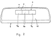
- the display device 6 has a display field 9 designed as a light window (Fig. 2) in a cover 10 of the housing 1 of the Brake light 5 is integrated.
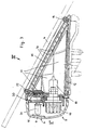
- the brake light housing 11 has a bottom 12 with which it is on the parcel shelf 3 or on a frame 13 (Fig. 5) is attached to the the parcel shelf 3 is in turn held.
- the brake light housing 11 is one Light window 15 surrounding damping ring 14 on the rear window 4 on.
- the damping ring 14 is used Shielding the brake light so it doesn't get into that Vehicle interior falls.
- the light window 15 is known Way provided with lens elements 16 (Fig. 3).
- a step reflector 17 Within of the housing 11 are a step reflector 17, a Incandescent lamp 18 with a bulb holder 19 for that Brake light 5 and a circuit board 20 housed on the optical display elements 21, such as LEDs, incandescent lamps and the like, are provided behind the display panel 9 lie, which is formed by a lens is.
- the circuit board 20 can also be provided in the cover 10 be.
- the housing 11 and the cover 10 are known per se releasable locking devices 24, 25 held together, so that the electronics or the light bulb 18 of the Brake light are easily accessible.
- the display panel 9 extends in the longitudinal direction of the Cover 10 and is preferably symmetrical about the transverse central plane E of the housing 11. As FIG. 2 shows, lies the display field 9 at a short distance from the lower edge of the lid. It preferably has three rectangular ones of the same size Window areas 9a to 9c, which are colored differently are red, yellow and green.
- Window areas 9a to 9c which are colored differently are red, yellow and green.
- the visual display with an acoustic display be coupled. For example, when lighting up of the first window area 9a, for example is colored red, a continuous tone, when the middle, yellow colored window area 9b several Piping sounds and when the window area 9c lights up, which is colored green, a single beep sounds.
- the driver of vehicle 1 is thereby optimally above it informs how large the distance of the vehicle 1 from rear vehicle 2 is. This distance is still sufficiently large, then the green window area lights up 9c. An additional acoustic signal sounds a single beep. Will the distance to the rear Vehicle 2 lower, for example 0.5 m, then the yellow window area 9b lights up. In addition can beep multiple beeps. The distance is very low, e.g. B only 15 cm, then the red one lights up Window area 9a. At the same time, the continuous tone can be heard if an acoustic signal is provided is. The driver then knows that he is stopping his vehicle 1 got to.
- the distance of the vehicle 1 can Backing up to any obstacle monitored become.
- On the circuit board 20 is the for the sensor 8 required control in known Formed way and is therefore not described in detail.
- the monitoring device is supplied with power via the vehicle battery. But it is also possible to Power supply to the monitoring device a battery to provide.
- the display panel 9 faces the driver, he can easily recognize the visual display when reversing, by watching them from the inside rearview mirror or turns to go straight to the visual display to look. This makes it inexperienced, for example Motorists easily possible, safely in to park tight parking spaces.
- the display device 6 Since the display device 6 is housed in the lamp housing 11 is a separate housing for the display device not mandatory. Manufacturing costs and additional installation space can be saved. A line connection between the display device 6 and its electronics is eliminated because the electronics sits on the circuit board 20.
- the electronics on the circuit board 20 and the display device 6 are separated from the brake light 5 with Power supplied in a known manner with the (not shown) coupled brake pedal of the vehicle 1 is.
- the display device 6 and the associated electronics are then switched on when the vehicle 1 Reverse gear is engaged.
Landscapes
- Engineering & Computer Science (AREA)
- Radar, Positioning & Navigation (AREA)
- Remote Sensing (AREA)
- Mechanical Engineering (AREA)
- Physics & Mathematics (AREA)
- Acoustics & Sound (AREA)
- Computer Networks & Wireless Communication (AREA)
- General Physics & Mathematics (AREA)
- Human Computer Interaction (AREA)
- Lighting Device Outwards From Vehicle And Optical Signal (AREA)
- Optical Radar Systems And Details Thereof (AREA)
- Measurement Of Velocity Or Position Using Acoustic Or Ultrasonic Waves (AREA)
Description
Die Erfindung betrifft eine Überwachungseinrichtung nach dem Oberbegriff des Anspruches 1.The invention relates to a monitoring device according to the preamble of claim 1.
Es ist bekannt, im Heckbereich eines Kraftfahrzeuges Ultraschallsensoren vorzusehen, mit denen beim Rückwärtsfahren der Abstand zu einem hinter dem Fahrzeug befindlichen Hindernis überwacht werden kann. Innerhalb des Fahrzeuges befindet sich eine optische und/oder akustische Warneinrichtung, die dem Fahrer anzeigt, wie weit er noch vom Hindernis entfernt ist. Die entsprechenden Anzeigen sowie die zugehörige Elektronik sind in gesonderten Gehäusen untergebracht, die im Fahrzeug eingebaut sind. Nachteilig bei dieser bekannten Lösung ist, daß für die einzelnen Teile dieser Überwachungseinrichtung unterschiedliche Gehäuse erforderlich sind. Dadurch ist die Überwachungseinrichtung in der Herstellung aufwendig und teuer. Außerdem ist die Montage der Überwachungseinrichtung wegen der zahlreichen Einzelteile aufwendig.It is known to use ultrasonic sensors in the rear area of a motor vehicle to provide for the distance when reversing an obstacle behind the vehicle can. There is an optical and / or inside the vehicle acoustic warning device that shows the driver how far he still has is away from the obstacle. The corresponding advertisements as well as the associated electronics are housed in separate housings, installed in the vehicle. A disadvantage of this known solution is that for the individual parts of this monitoring device different housings are required. This makes the monitoring device complex and expensive to manufacture. Furthermore is the assembly of the monitoring device because of the numerous Individual parts are complex.
Bei der gattungsgemäßen Überwachungseinrichtung (US-A-4,801,938) ist eine Empfangseinrichtung in einem im Heckbereich des Fahrzeuges befestigten Bremsleuchtengehäuse untergebracht. Die Überwachungseinrichtung dient als Radarwarngerät, mit dem von zur Geschwindigkeitskontrolle auf den Straßen aufgestellten Radarmeßgeräten ausgesandte Radarstrahlen erfaßt und dem Fahrer angezeigt werden. Innerhalb des Bremsleuchtengehäuses sitzen ein optisches und ein akustisches Sensorelement, deren Strahlen bzw. Schallwellen von einem Detektor erfaßt und über unterschiedliche Signalwege einem optischen sowie einem akustischen Anzeigeelement zugeleitet werden. Diese Anzeigeelemente sind an der Außenseite der Rückwand des Bremsleuchtengehäuses vorgesehen. Da die Bremsleuchte auf der Hutablage des Kraftfahrzeuges befestigt ist, besteht durch auf ihr abgelegte und während des Fahrens herumrutschende Gegenstände die Gefahr, daß die Anzeigeelemente beschädigt oder gar abgerissen werden. Dann kann diese Überwachungseinrichtung ihre Warnfunktion nicht mehr erfüllen. Darüber hinaus kann mit dieser Überwachungseinrichtung der Abstand des Kraftfahrzeuges von einem hinter ihm befindlichen Hindernis nicht festgestellt und angezeigt werden.In the generic monitoring device (US-A-4,801,938) is a receiver in a rear area the brake light housing attached to the vehicle. The monitoring device serves as a radar warning device with which for speed control radar measuring devices installed on the streets emitted radar beams are detected and displayed to the driver become. Sit inside the brake light housing optical and an acoustic sensor element, whose rays or Sound waves detected by a detector and over different Signal paths an optical and an acoustic display element be forwarded. These display elements are on the outside the rear wall of the brake light housing. Since the Brake light is attached to the parcel shelf of the motor vehicle, consists of being placed on it and sliding around while driving Objects the risk that the display elements are damaged or even be demolished. Then this monitoring device no longer fulfill their warning function. Furthermore can with this monitoring device the distance of the motor vehicle not detected by an obstacle behind it and be displayed.
Der Erfindung liegt die Aufgabe zugrunde, die gattungsgemäße Überwachungseinrichtung so auszubilden, daß sie einfach und kostengünstig in der Herstellung ist, sich einfach und bei geringstem Platzbedarf montieren läßt und ermöglicht, den Abstand des Fahrzeuges von einem Hindernis dem Fahrer deutlich anzuzeigen.The invention has for its object the generic Train monitoring device so that it is simple and inexpensive is easy to manufacture and at the least Space requirements can be mounted and allows the distance of the vehicle to clearly indicate to the driver of an obstacle.
Diese Aufgabe wird bei der gattungsgemäßen Überwachungseinrichtung erfindungsgemäß mit den kennzeichnenden Merkmalen des Anspruches 1 gelöst.This task is carried out in the generic monitoring device according to the invention with the characteristic features of Claim 1 solved.
Mit der erfindungsgemäßen Überwachungseinrichtung läßt sich einfach und zuverlässig genau der Abstand des Kraftfahrzeuges von einem hinter ihm befindlichen Hindernis erfassen und anzeigen. Über die Anzeigefelder des Lichtfensters kann dem Fahrer auf konstruktiv einfache Weise zuverlässig mitgeteilt werden, wie groß der Abstand seines Kraftfahrzeuges vom Hindernis ist. Dadurch können insbesondere auch ungeübte Fahrer gefahrlos selbst in enge Parklücken einparken. Das Anzeigeelement liegt innerhalb des Bremsleuchtengehäuses und kann darum von auf der Hutablage abgelegten und hin und her rutschenden Gegenständen nicht beschädigt oder gar abgerissen werden. Dadurch ist gewährleistet, daß die erfindungsgemäße Überwachungseinrichtung ihre Sicherungsfunktion über eine lange Einsatzdauer gewährleistet. The monitoring device according to the invention is simple and reliably exactly the distance of the motor vehicle from detect and display an obstacle behind it. over The display fields of the light window can be constructive for the driver easily communicated reliably how large the distance his motor vehicle is from the obstacle. This can in particular Even inexperienced drivers can park safely in tight parking spaces. The display element is located inside the brake light housing and can therefore be put on the parcel shelf and back and sliding objects are not damaged or even torn off become. This ensures that the invention Monitoring device its security function over a long Guaranteed service life.
Weitere Merkmale der Erfindung ergeben sich aus den weiteren Ansprüchen, der Beschreibung und den Zeichnungen.Further features of the invention result from the others Claims, the description and the drawings.
Die Erfindung wird nachstehend anhand eines in den Zeichnungen dargestellten Ausführungsbeispieles näher beschrieben. Es zeigt:
- Fig. 1
- eine Draufsicht auf ein Fahrzeug mit einer erfindungsgemäßen Überwachungseinrichtung,
- Fig. 2
- eine Bremsleuchte eines Kraftfahrzeuges, in der eine Anzeigeeinrichtung der erfindungsgemäßen Überwachungseinrichtung untergebracht ist, in Ansicht gemäß Pfeil II in Fig. 3,
- Fig. 3
- die Bremsleuchte mit der Anzeigeeinrichtung in vergrößerter Darstellung und im Längsschnitt,
- Fig. 4
- die Bremsleuchte nach Fig. 3 in Ansicht gemäß Pfeil IV in Fig. 3,
- Fig. 5
- die Bromsleuchte mit der Anzeigeeinrichtung in Seitenansicht.
- Fig. 1
- a plan view of a vehicle with a monitoring device according to the invention,
- Fig. 2
- a brake light of a motor vehicle, in which a display device of the monitoring device according to the invention is accommodated, in a view according to arrow II in FIG. 3,
- Fig. 3
- the brake light with the display device in an enlarged view and in longitudinal section,
- Fig. 4
- 3 in view according to arrow IV in Fig. 3,
- Fig. 5
- the bromine light with the indicator in side view.
Fig. 1 zeigt zwei mit Abstand hintereinander angeordnete
Pkws 1 und 2. Im ersten Pkw ist im Innenraum im Heckbereich
eine hochgesetzte Bremsleuchte 5 vorgesehen, die
vorzugsweise auf einer Hutablage 3 befestigt ist und an
der Heckscheibe 4 des Kraftfahrzeuges anliegt (Fig. 3).
Die Bremsleuchte 5 ist mit einer Anzeigeeinrichtung bzw.
-einheit 6 versehen, mit welcher beim Rückwärtsfahren
des Pkws 1 der Abstand zu einem rückwärtigen Fahrzeug 2
(Fig. 1) angezeigt wird. Über einen im Heckbereich, vorzugsweise
an der Stoßstange 7, vorgesehenen und in Fig.
1 nur schematisch dargestellten Ultraschall- oder Infrarotsensor
8 wird der Abstand zum rückwärtigen Fahrzeug 2
gemessen und über eine (nicht dargestellte), jedoch an
sich bekannte elektronische Einrichtung ein entsprechendes
Signal an die Anzeigeeinrichtung 6 geleitet. Die Anzeigeeinrichtung
6 und der Sensor 8 sind Teil der Überwachungseinrichtung,
die insbesondere als Einparkhilfe
eingesetzt werden kann. Die Anzeigeeinrichtung 6 weist
ein als Lichtfenster ausgebildetes Anzeigefeld 9 auf
(Fig. 2), das in einen Deckel 10 des Gehäuses 1 der
Bremsleuchte 5 integriert ist. Das Bremsleuchtengehäuse
11 hat einen Boden 12, mit dem es auf der Hutablage 3
bzw. auf einem Rahmen 13 (Fig. 5) befestigt ist, an dem
die Hutablage 3 ihrerseits gehalten ist. Wie Fig. 3
zeigt, liegt das Bremsleuchtengehäuse 11 mit einem ein
Lichtfenster 15 umgebenden Dämpfungsring 14 an der Heckscheibe
4 an. Außerdem dient der Dämpfungsring 14 zur
Abschirmung des Bremslichtes, damit es nicht in das
Fahrzeuginnere fällt. Das Lichtfenster 15 ist in bekannter
Weise mit Linsenelementen 16 versehen (Fig. 3). Innerhalb
des Gehäuses 11 sind ein Stufenreflektor 17, eine
Glühlampe 18 mit einer Glühlampenfassung 19 für das
Bremslicht 5 und eine Leiterplatte 20 untergebracht, auf
der optische Anzeigeelemente 21, wie LEDs, Glühlampen
und dergleichen, vorgesehen sind, die hinter dem Anzeigefeld
9 liegen, das durch eine Lichtscheibe gebildet
ist. Die Leiterplatte 20 kann auch im Deckel 10 vorgesehen
sein.Fig. 1 shows two spaced one behind the other
Cars 1 and 2. In the first car is in the interior in the rear area
a raised
Das Gehäuse 11 und der Deckel 10 sind durch an sich bekannte
lösbare Rasteinrichtungen 24, 25 zusammengehalten,
so daß die Elektronik bzw. die Glühlampe 18 der
Bremsleuchte leicht zugänglich sind.The
Das Anzeigefeld 9 erstreckt sich in Längsrichtung des
Deckels 10 und liegt vorzugsweise symmetrisch zur Quermittelebene
E des Gehäuses 11. Wie Fig. 2 zeigt, liegt
das Anzeigefeld 9 mit geringem Abstand vom unteren Dekkelrand.
Es hat vorzugsweise drei gleich große rechtekkige
Fensterbereiche 9a bis 9c, die unterschiedlich eingefärbt
sind, nämlich rot, gelb und grün. Vorteilhaft
kann die optische Anzeige mit einer akustischen Anzeige
gekoppelt sein. So können beispielsweise beim Aufleuchten
des ersten Fensterbereiches 9a, der beispielsweise
rot eingefärbt ist, ein Dauerton, beim Aufleuchten des
mittleren, gelb eingefärbten Fensterbereiches 9b mehrere
Pipstöne und beim Aufleuchten des Fensterbereiches 9c,
der grün eingefärbt ist, ein einziger Piepston ertönen.
Der Fahrer des Fahrzeuges 1 wird dadurch optimal darüber
informiert, wie groß der Abstand des Fahrzeuges 1 vom
rückwärtigen Fahrzeug 2 ist. Ist dieser Abstand noch
ausreichend groß, dann leuchtet der grüne Fensterbereich
9c auf. Bei einer zusätzlichen akustischen Anzeige ertönt
ein einziger Piepston. Wird der Abstand zum hinteren
Fahrzeug 2 geringer, beispielsweise 0,5 m, dann
leuchtet der gelbe Fensterbereich 9b auf. Zusätzlich
können mehrere Piepstöne ertönen. Ist der Abstand sehr
gering, z. B nur noch 15 cm, dann leuchtet der rote
Fensterbereich 9a auf. Gleichzeitig kann der Dauerton zu
hören sein, falls eine akustische Anzeige vorgesehen
ist. Der Fahrer weiß dann, daß er sein Fahrzeug 1 anhalten
muß.The
Mit dem Sensor 8 kann der Abstand des Fahrzeuges 1 beim
Rückwärtsfahren zu jedem beliebigen Hindernis überwacht
werden. Auf der Leiterplatte 20 befindet sich die für
den Sensor 8 erforderliche Steuerung, die in bekannter
Weise ausgebildet und darum nicht näher beschrieben ist.
Die Stromversorgung der Überwachungseinrichtung erfolgt
über die Fahrzeugbatterie. Es ist aber auch möglich, zur
Stromversorgung der Überwachungseinrichtung einen Akku
vorzusehen.With the
Da das Anzeigefeld 9 dem Fahrer zugewandt ist, kann er
beim Rückwärtsfahren die optische Anzeige einfach erkennen,
indem er sie über den Innenrückspiegel beobachtet
oder sich umwendet, um direkt auf die optische Anzeige
zu blicken. Dadurch ist es beispielsweise auch ungeübten
Kraftfahrzeugfahrern ohne weiteres möglich, sicher in
enge Parklücken einzuparken.Since the
Da die Anzeigeeinrichtung 6 im Leuchtengehäuse 11 untergebracht
ist, ist ein gesondertes Gehäuse für die Anzeigeeinrichtung
nicht erforderlich. Fertigungskosten und
zusätzlicher Einbauraum können dadurch eingespart werden.
Eine Leitungsverbindung zwischen der Anzeigeeinrichtung
6 und ihrer Elektronik entfällt, da die Elektronik
auf der Leiterplatte 20 sitzt.Since the
Die Elektronik auf der Leiterplatte 20 und die Anzeigeeinrichtung
6 werden getrennt von der Bremsleuchte 5 mit
Strom versorgt, die in bekannter Weise mit dem (nicht
dargestellten) Bremspedal des Fahrzeuges 1 gekoppelt
ist. Die Anzeigeeinrichtung 6 und die zugehörige Elektronik
werden dann eingeschaltet, wenn am Fahrzeug 1 der
Rückwärtsgang eingelegt wird.The electronics on the
Claims (8)
- A monitoring device arranged in the tail region of a motor vehicle (1), with at least one sensor (8) connected to an optical display unit (6) which is arranged in the interior of the motor vehicle (1) and which is mounted on a cover (10) of a housing (11) of a brake light (5) arranged in the rear-window area (4) inside the motor vehicle (1) and has a display element (21), characterized in that the monitoring device is provided for displaying the distance of the motor vehicle (1) from an obstacle (2), and the display unit (6) has a light window (9) which has adjacent display areas (9a to 9c) and is provided in the housing cover (10) and which is illuminated by the display element (21) arranged behind the housing cover (10) inside the housing (11).
- A monitoring device according to Claim 1, characterized in that the cover (10) is held in an engaged manner on the brake-light housing (11).
- A monitoring device according to Claim 1 or 2, characterized in that the display unit (6) together with its electrical or electronic control is arranged in the brake-light housing (11).
- A monitoring device according to Claim 4, characterized in that the light window (9) has three differently coloured display areas (9a to 9c) situated adjacent to one another.
- A monitoring unit according to one of Claims 1 to 6, characterized in that the display unit (6) is coupled to an acoustic signal transmitter.
- A monitoring device according to Claim 4 or 5, characterized in that each display area (9a to 9c) has associated therewith a different signalling tone or a different tone sequence.
- A monitoring device according to one of Claims 4 to 6, characterized in that one respective display element (21), preferably an LED lamp, is arranged in each case in the brake-light housing (11) behind each display area (9a to 9c).
- A monitoring device according to Claim 7, characterized in that the display elements (21) are arranged on a printed circuit board (20) in the brake-light housing (11).
Applications Claiming Priority (2)
| Application Number | Priority Date | Filing Date | Title |
|---|---|---|---|
| DE4410617 | 1994-03-26 | ||
| DE4410617A DE4410617A1 (en) | 1994-03-26 | 1994-03-26 | Distance monitoring device for reversing car |
Publications (2)
| Publication Number | Publication Date |
|---|---|
| EP0683068A1 EP0683068A1 (en) | 1995-11-22 |
| EP0683068B1 true EP0683068B1 (en) | 1999-06-02 |
Family
ID=6513986
Family Applications (1)
| Application Number | Title | Priority Date | Filing Date |
|---|---|---|---|
| EP95103381A Expired - Lifetime EP0683068B1 (en) | 1994-03-26 | 1995-03-09 | Control device |
Country Status (4)
| Country | Link |
|---|---|
| US (1) | US5541891A (en) |
| EP (1) | EP0683068B1 (en) |
| DE (2) | DE4410617A1 (en) |
| ES (1) | ES2132452T3 (en) |
Families Citing this family (21)
| Publication number | Priority date | Publication date | Assignee | Title |
|---|---|---|---|---|
| DE19505011C2 (en) * | 1995-02-15 | 2003-12-24 | Teves Gmbh Alfred | Arrangement of an optical rain sensor |
| DE19517015C2 (en) * | 1995-05-10 | 1998-11-19 | Moto Meter Gmbh | Brake light to be arranged in the area of the rear window |
| DE19545604C3 (en) * | 1995-12-07 | 2001-09-06 | Kostal Leopold Gmbh & Co Kg | Windshield wiper system for rear windows with a moisture sensor integrated in the brake light |
| DE19646375A1 (en) * | 1996-11-09 | 1998-05-14 | Teves Gmbh Alfred | Device for mounting in the rear area of vehicles with a distance measuring or warning device |
| DE19705131A1 (en) * | 1997-02-11 | 1998-08-13 | Reitter & Schefenacker Gmbh | Housing, preferably exterior rear view mirror for vehicles, in particular for motor vehicles |
| US6124647A (en) * | 1998-12-16 | 2000-09-26 | Donnelly Corporation | Information display in a rearview mirror |
| DE19811161A1 (en) | 1998-03-14 | 1999-09-16 | Volkswagen Ag | Indicator arrangement using vehicle driver's mirror |
| US6268803B1 (en) | 1998-08-06 | 2001-07-31 | Altra Technologies Incorporated | System and method of avoiding collisions |
| US6894608B1 (en) | 1999-07-22 | 2005-05-17 | Altra Technologies Incorporated | System and method for warning of potential collisions |
| DE19942637A1 (en) * | 1999-09-07 | 2001-03-29 | Volkswagen Ag | Interior rear view mirror is directed towards and positioned with respect to display device of reversing aid in rear of passenger compartment when display device is activated |
| DE19942636A1 (en) * | 1999-09-07 | 2001-03-08 | Volkswagen Ag | Display device for an electronic reversing aid |
| US6642839B1 (en) | 2000-02-16 | 2003-11-04 | Altra Technologies Incorporated | System and method of providing scalable sensor systems based on stand alone sensor modules |
| DE10023585B4 (en) * | 2000-05-13 | 2005-04-21 | Daimlerchrysler Ag | Display arrangement in a vehicle |
| DE10114932B4 (en) * | 2001-03-26 | 2005-09-15 | Daimlerchrysler Ag | Three-dimensional environment detection |
| US6933837B2 (en) | 2002-01-25 | 2005-08-23 | Altra Technologies Incorporated | Trailer based collision warning system and method |
| US7123168B2 (en) * | 2002-04-25 | 2006-10-17 | Donnelly Corporation | Driving separation distance indicator |
| FR2842781A1 (en) | 2002-07-25 | 2004-01-30 | Valeo Systemes Dessuyage | SIGNAL LIGHT AND DISPLAY DEVICE ARRANGED IN A HOUSING SHAPED IN PART BY THE BODY OF A VEHICLE |
| US20040080404A1 (en) * | 2002-10-28 | 2004-04-29 | White Tommy E. | Distance detection and display system for use in a vehicle |
| US7106213B2 (en) * | 2002-10-28 | 2006-09-12 | General Motors Corporation | Distance detection and display system for use in a vehicle |
| DE102007002258A1 (en) * | 2007-01-16 | 2008-07-17 | GM Global Technology Operations, Inc., Detroit | Optical display device for motor vehicle, has display unit arranged in orientation direction, where display unit displays information, which refers to danger potentials for motor vehicle in orientation direction |
| US20090184811A1 (en) * | 2008-01-23 | 2009-07-23 | Althoff Nicholas K | Methods and system for an impact avoidance system |
Family Cites Families (6)
| Publication number | Priority date | Publication date | Assignee | Title |
|---|---|---|---|---|
| US4290043A (en) * | 1979-10-16 | 1981-09-15 | Kaplan Irwin M | Method of and system for detecting marine obstacles |
| DE3207950A1 (en) * | 1982-03-05 | 1983-09-15 | Bosch Gmbh Robert | DISTANCE MEASURING DEVICE |
| US4801938A (en) * | 1987-01-12 | 1989-01-31 | Holmes Steven C | Remote output indicator for providing output indications from a remotely located radar detector which is adapted to be used in connection with a brake light indicator |
| US5059946A (en) * | 1989-05-10 | 1991-10-22 | Hollowbush Richard R | Ultrasonic obstacle detector |
| IT1256863B (en) * | 1992-02-11 | 1995-12-27 | OBSTACLE DETECTION SYSTEM IN PARTICULAR FOR VEHICLES | |
| DE4303066C2 (en) * | 1993-02-03 | 1994-08-11 | Steinbacher Peter Dipl Ing Fh | Parking assistance for motor vehicles |
-
1994
- 1994-03-26 DE DE4410617A patent/DE4410617A1/en not_active Withdrawn
-
1995
- 1995-03-09 EP EP95103381A patent/EP0683068B1/en not_active Expired - Lifetime
- 1995-03-09 DE DE59506074T patent/DE59506074D1/en not_active Expired - Lifetime
- 1995-03-09 ES ES95103381T patent/ES2132452T3/en not_active Expired - Lifetime
- 1995-03-23 US US08/409,316 patent/US5541891A/en not_active Expired - Lifetime
Also Published As
| Publication number | Publication date |
|---|---|
| US5541891A (en) | 1996-07-30 |
| ES2132452T3 (en) | 1999-08-16 |
| DE4410617A1 (en) | 1995-09-28 |
| DE59506074D1 (en) | 1999-07-08 |
| EP0683068A1 (en) | 1995-11-22 |
Similar Documents
| Publication | Publication Date | Title |
|---|---|---|
| EP0683068B1 (en) | Control device | |
| DE102007027529B3 (en) | Warning device for a motor vehicle | |
| DE19538770B4 (en) | Exterior rearview mirror for vehicles, preferably for motor vehicles | |
| DE202019101222U1 (en) | B-pillar proximity warning system for autonomous vehicles | |
| DE29712954U1 (en) | License plate for a motor vehicle | |
| DE20311415U1 (en) | Rear lamp set with built-in safety sensors | |
| DE102004042107A1 (en) | Mirror arrangement for a vehicle comprises a mirror pane having a display region with thin antireflection light-permeable strips and a light indicating unit | |
| DE2641006A1 (en) | Optical warning system for rescue vehicle - has lighting strip consisting of several lamps switched in succession mounted across and along sides of roof | |
| DE102016202039A1 (en) | Camera module for a motor vehicle | |
| DE19730967A1 (en) | Automobile signalling device | |
| EP0699560B1 (en) | Reversing light for vehicle | |
| DE60311193T2 (en) | Signal light and display device which are arranged in a partially existing from the vehicle body housing | |
| EP2138351B1 (en) | Warning apparatus for a motor vehicle | |
| DE19646375A1 (en) | Device for mounting in the rear area of vehicles with a distance measuring or warning device | |
| EP1680305A2 (en) | Mirror glass component comprising an integrated luminous film | |
| DE3225407A1 (en) | Warning device for installation on motor vehicles | |
| EP2783916A1 (en) | Circuit board, display device and exterior rear view mirror | |
| EP1214222B1 (en) | Display element for an electronic back-up assist system | |
| DE60303492T2 (en) | Improved signaling device for motor vehicles | |
| DE3049058A1 (en) | Speed light for vehicle - is mounted behind front windscreen and lights up certain speed | |
| DE10154132A1 (en) | Additional brake light for road vehicle has at least one electrical light body mounted beneath manufacturer's emblem consisting of at least one transparent and at least one opaque element | |
| DE4437408A1 (en) | Transmitting/receiving parts for acoustic, image-like signals, which parts are constructed to form, for motorised vehicles, an installation for emergencies, for ordering road users to do something, for making them aware of dangers and for warning them | |
| DE20122377U1 (en) | Additional brake light for road vehicle has at least one electrical light body mounted beneath manufacturer's emblem consisting of at least one transparent and at least one opaque element | |
| DE102008035682A1 (en) | Traffic light for emergency vehicle e.g. ambulance, has warning light that illuminates and flashes within radius of specific degrees when emergency vehicle with special signals approaches in case of emergency | |
| DE29820508U1 (en) | Warning device for vehicles |
Legal Events
| Date | Code | Title | Description |
|---|---|---|---|
| PUAI | Public reference made under article 153(3) epc to a published international application that has entered the european phase |
Free format text: ORIGINAL CODE: 0009012 |
|
| AK | Designated contracting states |
Kind code of ref document: A1 Designated state(s): BE DE ES FR GB IT LU NL SE |
|
| 17P | Request for examination filed |
Effective date: 19960403 |
|
| 17Q | First examination report despatched |
Effective date: 19961023 |
|
| GRAG | Despatch of communication of intention to grant |
Free format text: ORIGINAL CODE: EPIDOS AGRA |
|
| GRAG | Despatch of communication of intention to grant |
Free format text: ORIGINAL CODE: EPIDOS AGRA |
|
| GRAH | Despatch of communication of intention to grant a patent |
Free format text: ORIGINAL CODE: EPIDOS IGRA |
|
| GRAH | Despatch of communication of intention to grant a patent |
Free format text: ORIGINAL CODE: EPIDOS IGRA |
|
| ITF | It: translation for a ep patent filed | ||
| GRAA | (expected) grant |
Free format text: ORIGINAL CODE: 0009210 |
|
| AK | Designated contracting states |
Kind code of ref document: B1 Designated state(s): BE DE ES FR GB IT LU NL SE |
|
| REF | Corresponds to: |
Ref document number: 59506074 Country of ref document: DE Date of ref document: 19990708 |
|
| ET | Fr: translation filed | ||
| GBT | Gb: translation of ep patent filed (gb section 77(6)(a)/1977) |
Effective date: 19990719 |
|
| REG | Reference to a national code |
Ref country code: ES Ref legal event code: FG2A Ref document number: 2132452 Country of ref document: ES Kind code of ref document: T3 |
|
| PLBE | No opposition filed within time limit |
Free format text: ORIGINAL CODE: 0009261 |
|
| STAA | Information on the status of an ep patent application or granted ep patent |
Free format text: STATUS: NO OPPOSITION FILED WITHIN TIME LIMIT |
|
| 26N | No opposition filed | ||
| REG | Reference to a national code |
Ref country code: GB Ref legal event code: IF02 |
|
| PGFP | Annual fee paid to national office [announced via postgrant information from national office to epo] |
Ref country code: SE Payment date: 20020225 Year of fee payment: 8 |
|
| PGFP | Annual fee paid to national office [announced via postgrant information from national office to epo] |
Ref country code: ES Payment date: 20020325 Year of fee payment: 8 |
|
| PGFP | Annual fee paid to national office [announced via postgrant information from national office to epo] |
Ref country code: BE Payment date: 20020328 Year of fee payment: 8 |
|
| PGFP | Annual fee paid to national office [announced via postgrant information from national office to epo] |
Ref country code: NL Payment date: 20020329 Year of fee payment: 8 |
|
| PGFP | Annual fee paid to national office [announced via postgrant information from national office to epo] |
Ref country code: LU Payment date: 20020419 Year of fee payment: 8 |
|
| PG25 | Lapsed in a contracting state [announced via postgrant information from national office to epo] |
Ref country code: LU Free format text: LAPSE BECAUSE OF NON-PAYMENT OF DUE FEES Effective date: 20030309 |
|
| PG25 | Lapsed in a contracting state [announced via postgrant information from national office to epo] |
Ref country code: SE Free format text: LAPSE BECAUSE OF NON-PAYMENT OF DUE FEES Effective date: 20030310 Ref country code: ES Free format text: LAPSE BECAUSE OF NON-PAYMENT OF DUE FEES Effective date: 20030310 |
|
| PG25 | Lapsed in a contracting state [announced via postgrant information from national office to epo] |
Ref country code: BE Free format text: LAPSE BECAUSE OF NON-PAYMENT OF DUE FEES Effective date: 20030331 |
|
| BERE | Be: lapsed |
Owner name: *REITTER & SCHEFENACKER G.M.B.H. & CO. K.G. Effective date: 20030331 |
|
| PG25 | Lapsed in a contracting state [announced via postgrant information from national office to epo] |
Ref country code: NL Free format text: LAPSE BECAUSE OF NON-PAYMENT OF DUE FEES Effective date: 20031001 |
|
| EUG | Se: european patent has lapsed | ||
| NLV4 | Nl: lapsed or anulled due to non-payment of the annual fee |
Effective date: 20031001 |
|
| REG | Reference to a national code |
Ref country code: ES Ref legal event code: FD2A Effective date: 20030310 |
|
| PG25 | Lapsed in a contracting state [announced via postgrant information from national office to epo] |
Ref country code: IT Free format text: LAPSE BECAUSE OF NON-PAYMENT OF DUE FEES;WARNING: LAPSES OF ITALIAN PATENTS WITH EFFECTIVE DATE BEFORE 2007 MAY HAVE OCCURRED AT ANY TIME BEFORE 2007. THE CORRECT EFFECTIVE DATE MAY BE DIFFERENT FROM THE ONE RECORDED. Effective date: 20050309 |
|
| PGFP | Annual fee paid to national office [announced via postgrant information from national office to epo] |
Ref country code: GB Payment date: 20080320 Year of fee payment: 14 |
|
| GBPC | Gb: european patent ceased through non-payment of renewal fee |
Effective date: 20090309 |
|
| PG25 | Lapsed in a contracting state [announced via postgrant information from national office to epo] |
Ref country code: GB Free format text: LAPSE BECAUSE OF NON-PAYMENT OF DUE FEES Effective date: 20090309 |
|
| PGFP | Annual fee paid to national office [announced via postgrant information from national office to epo] |
Ref country code: FR Payment date: 20120403 Year of fee payment: 18 |
|
| PGFP | Annual fee paid to national office [announced via postgrant information from national office to epo] |
Ref country code: DE Payment date: 20130321 Year of fee payment: 19 |
|
| REG | Reference to a national code |
Ref country code: FR Ref legal event code: ST Effective date: 20131129 |
|
| PG25 | Lapsed in a contracting state [announced via postgrant information from national office to epo] |
Ref country code: FR Free format text: LAPSE BECAUSE OF NON-PAYMENT OF DUE FEES Effective date: 20130402 |
|
| REG | Reference to a national code |
Ref country code: DE Ref legal event code: R119 Ref document number: 59506074 Country of ref document: DE |
|
| REG | Reference to a national code |
Ref country code: DE Ref legal event code: R119 Ref document number: 59506074 Country of ref document: DE Effective date: 20141001 |
|
| PG25 | Lapsed in a contracting state [announced via postgrant information from national office to epo] |
Ref country code: DE Free format text: LAPSE BECAUSE OF NON-PAYMENT OF DUE FEES Effective date: 20141001 |