EP0683069A1 - Eclairage intérieur pour véhicule - Google Patents
Eclairage intérieur pour véhicule Download PDFInfo
- Publication number
- EP0683069A1 EP0683069A1 EP95103806A EP95103806A EP0683069A1 EP 0683069 A1 EP0683069 A1 EP 0683069A1 EP 95103806 A EP95103806 A EP 95103806A EP 95103806 A EP95103806 A EP 95103806A EP 0683069 A1 EP0683069 A1 EP 0683069A1
- Authority
- EP
- European Patent Office
- Prior art keywords
- interior
- light
- display
- light sources
- switching
- Prior art date
- Legal status (The legal status is an assumption and is not a legal conclusion. Google has not performed a legal analysis and makes no representation as to the accuracy of the status listed.)
- Granted
Links
- 230000001681 protective effect Effects 0.000 claims description 8
- 230000001105 regulatory effect Effects 0.000 claims description 3
- 239000013078 crystal Substances 0.000 abstract 1
- 230000001419 dependent effect Effects 0.000 description 3
- 238000010586 diagram Methods 0.000 description 3
- 238000009434 installation Methods 0.000 description 3
- 238000013021 overheating Methods 0.000 description 3
- 238000001514 detection method Methods 0.000 description 1
- 230000006870 function Effects 0.000 description 1
- 238000010438 heat treatment Methods 0.000 description 1
- 230000009993 protective function Effects 0.000 description 1
- 230000005855 radiation Effects 0.000 description 1
- 230000000717 retained effect Effects 0.000 description 1
Images


Classifications
-
- B—PERFORMING OPERATIONS; TRANSPORTING
- B60—VEHICLES IN GENERAL
- B60Q—ARRANGEMENT OF SIGNALLING OR LIGHTING DEVICES, THE MOUNTING OR SUPPORTING THEREOF OR CIRCUITS THEREFOR, FOR VEHICLES IN GENERAL
- B60Q3/00—Arrangement of lighting devices for vehicle interiors; Lighting devices specially adapted for vehicle interiors
- B60Q3/80—Circuits; Control arrangements
Definitions
- the invention relates to an interior light for motor vehicles, with a multi-part housing, which has at least a first light source for illuminating the interior of the motor vehicle and at least a second light source for illuminating a display arranged in the housing, and with switching means for simultaneous or separate switching on and off of the light sources.
- An interior light for motor vehicles is known from German published patent application DE 37 30 284 A1, which has a multi-part housing. Light sources for illuminating the interior of the motor vehicle are arranged in the housing. The interior light also has a display to show the time, the interior temperature or the outside temperature. The light sources are connected to a switching means, which is arranged in the power supply and is designed in a known manner as a multiple switch, with the switching positions "off", "actuation of the interior light via the door contacts of the motor vehicle” and “continuous light". In the known interior light it proves disadvantageous that the display is only suitable for displaying the time, the interior temperature or the outside temperature.
- the interior light and in particular the display are not protected against overheating during the usual installation in the roof area of the vehicle.
- the vehicle When the vehicle is exposed to sunlight and the interior light is put into operation, it heats up to such an extent that components of the interior light, in particular the display, can be destroyed.
- the use of materials that withstand the elevated temperatures lead to a cost-intensive design of the interior light.
- the invention has for its object to provide an interior light for motor vehicles, the one illuminated Has display device for the display of different information, which ensures good visibility in any situation, which is optimally protected against overheating despite the installation in the roof area of the vehicle and which can be produced inexpensively.
- the display is an LC display that is connected to control electronics for displaying different information, as a result of which different changing information, which can consist of both alphanumeric data and symbols, can be displayed.
- different changing information which can consist of both alphanumeric data and symbols.
- control electronics is connected to an electronic circuit which has switching means for switching on and off at least the second light source, thereby ensuring that the display is always illuminated when, depending on the operating conditions of the motor vehicle, information about the Display.
- the LC display is assigned a protective circuit with at least one temperature sensor for dimming and / or switching off at least one of the light sources when a predetermined temperature threshold value is exceeded results in the advantage that, for example, the interior light is not additionally caused by strong sunlight on the motor vehicle the operation of the light sources is heated and there is therefore no risk of damage to the components of the interior light, in particular the display, from overheating.
- components for the interior light can be used as a result are designed for lower temperatures, which means that the interior light can be manufactured cheaply.
- the specified features also ensure that the information shown by the display can be easily recognized in any situation, because in the event of strong solar radiation on the motor vehicle in which the second light source and / or the first light source are dimmed and / or switched off due to the temperature Given the high brightness in the motor vehicle, the readability of the LC display is retained.
- the temperature sensor is at least one thermistor arranged in the power supply of the first and / or the second light source, as a result of which a particularly simple and inexpensive temperature-dependent shutdown of the light sources is made possible.
- the temperature sensor is part of a device for regulating the interior temperature results in the advantage that it is possible in a cost-effective manner to use a component already present in the motor vehicle for the temperature-dependent switching off of the light sources.
- the temperature sensor is connected to the protective circuit, that the protective circuit is part of the electronic circuit and that the electronic circuit has all the switching means for dimming and / or for switching on and off all the light sources of the interior lamp, which makes it particularly simple and Inexpensive embodiment is made possible, in which a high level of security for the operation of the interior light and the LC display arranged in the interior light is guaranteed.
- the fact that the temperature sensor is arranged in the housing gives the advantage that the temperature in the housing of the interior light is measured as well as possible and that there is the advantage that the interior light is as compact and simple as possible.
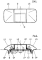
- FIG. 1 shows a plan view of an embodiment of an interior lamp according to the invention.
- This has a multi-part housing (G) with two external ones Light discs (LS) and a display (D) arranged in the housing (G).
- the interior light has a roof-shaped design, so that the display (D) is arranged obliquely and is in the field of view of the viewer when the interior light is installed in the roof.
- the display is designed as an LC display (D) and is suitable for displaying different information.
- the LC display (D) can be designed as a black and white display, but it can also be designed as a color display.
- the LC display (D) can be divided into several areas depending on the information to be displayed.
- the arrangement of the light panes (LS), their number and the arrangement and size of the LC display (D) can be designed differently.
- FIG. 2 shows a longitudinal section through the interior light shown in Figure 1.
- the multi-part housing (G) is constructed here, for example, from a housing part (GT), two light panes (LS), a base plate (GP) and an electrical circuit board (LP).
- Fastening elements (B) are provided for the self-locking fastening of the interior light in the cutout of a vehicle roof lining.
- Connectors (ST) are provided for the electrical connection of the interior light.
- a first light source (L1) for illuminating the interior of the motor vehicle is arranged under each of the light panes (LS).
- the first light sources (L1) are connected to switching means via at least one of the plug connectors (ST) for simultaneous or separate switching on and off.
- two second light sources (L2) are arranged, for example, which backlight the LC display (D) shown in FIG. 1 for better recognition of the information to be displayed.
- the second light sources (L2) are electrically conductive via at least one of the plug connectors (ST) connected with switching means for switching on and off.
- the first light sources (L1) have a higher power consumption than the second light sources (L2).
- the embodiment of an interior light shown in FIG. 1 and FIG. 2 is suitable for installation in the roof lining of the rear of a motor vehicle.
- FIG. 3 shows a basic circuit diagram of a protective circuit for the embodiment of an interior light for motor vehicles shown in FIG. 1 and FIG. 2.
- the first light sources (L1) for illuminating the interior of the motor vehicle are supplied with current via a first power supply circuit.
- the first light sources (L1) are arranged in parallel.
- a temperature sensor (T) is arranged in the power supply circuit in series with the first light sources (L1) and is designed as a thermistor (T) and in particular as a PTC resistor.
- the resistance value increases at a predetermined temperature such that the current supply to the first light sources (L1) is reduced or interrupted.
- the second light sources (L2) can be connected to the supply voltage via a second power supply circuit.
- the second light sources (L2) are arranged parallel to one another and a temperature sensor (T), which is designed as a thermistor (T), is arranged in series with the light sources (L2).
- T temperature sensor
- the second light sources (L2) each serve to backlight an LC display (D).
- a thermistor (T) only has to be arranged in one of the power supply circuits.
- the second light sources (L2) can have a lower power consumption than the first light sources (L1). Based on this, it may be sufficient to arrange the thermistor (T) solely in the first power supply circuit that supplies the first light sources (L1). On the other hand, if the first light sources (L1) are arranged far from the display (D), it may be sufficient to arrange the thermistor (T) in the second power supply circuit in which the second light sources (L2) are arranged.
- FIG. 4 shows a basic illustration for the recognizability of an LC display (D).
- the second light source (L2) is located in a power supply circuit which is energized, for example, by control electronics (not shown here) whenever information has to be displayed on the LC display (D).
- a temperature sensor (T) which is designed as a thermistor (T) is also arranged in the power supply circuit in FIG. 4 in series with the second light source (L2). This interrupts the current to the second light source (L2) when a certain temperature threshold is exceeded. If the power supply to the second light source (L2) is interrupted, the LC display (D) is no longer backlit.
- FIG. 4 shows a sun, an eye and a ray path between the eye, display (D) and sun.
- FIG. 5 shows a block diagram of a circuit arrangement for operating an interior light according to the invention.
- the Circuit arrangement comprises an electronic circuit (S), which can be designed, for example, as a microprocessor, which is connected to the supply voltage (UB) and ground.
- the electronic circuit has several inputs (E1, E2), via which, for example, the signal of a temperature sensor (T), which is not shown here, is fed to the electronic circuit (S).
- the temperature sensor (T) can be arranged in the interior light for measuring the temperature of the interior light.
- the temperature sensor (T) can also be part of a device for regulating the interior temperature.
- the temperature sensor (T) can also be arranged, for example, in the area of the dashboard of the motor vehicle.
- data or control signals can be supplied to the electronic circuit (S) via further inputs.
- the electronic circuit (S) can also be connected, for example, to a bus system of the motor vehicle via such inputs.
- the circuit (S) has switching means for switching the second light sources (L2) on and off, the power supply circuit of which is connected to the circuit (S).
- a first diode (D1) is arranged in the connecting line via which the second light sources (L2) can be connected by the circuit to the supply voltage (UB).
- the control electronics (A) for the LC display (D) are also connected to this connecting line of the circuit (S).
- the second light sources (L2) and the control electronics (A) are based here, for example, on a ground that can also be provided by the circuit (S). If the circuit (S) is arranged away from the control electronics (A), a close body mass can also be selected for the specified power supply circuits.
- the circuit arrangement shown also includes the power supply circuit of the first light sources (L1) which illuminate the interior of the motor vehicle. This power supply circuit is assigned a switch (H), which is a multi-function switch in a known manner.
- the light sources (L1) which are also arranged here in parallel, for example, can be connected to the supply voltage (UB) via one of the outputs of the switch. Depending on the switch position, the first light sources (L1) are operated with permanent light (DL) or are switched on and off depending on door contact switches (TK).
- a second diode (D2) is arranged between the first light sources (L1) and the input of the switch (H) labeled TK.
- the signals of the switch (H) can be fed directly via further inputs to the electronic circuit (S), to which the power supply circuit of the first light source (L1) is then also connected and switched by it.
- the electronic circuit (S) comprises a protective circuit, not shown, with a threshold value detection for the temperature signal present via one of the inputs (E1, E2), the first and / or second light sources (L1, L2) being switched off when a predetermined temperature threshold value is exceeded.
- the components shown in Figure 5 can all be arranged in the housing of the interior light.
- the electronic circuit (S) can be arranged outside the interior light.
- further interior lights of the motor vehicle can be connected to the electronic circuit (S) for simultaneous or separate switching on and off. It proves to be particularly advantageous when all the lights in the interior of the motor vehicle are switched off to protect the lights when the predetermined temperature threshold is exceeded.
Landscapes
- Engineering & Computer Science (AREA)
- Mechanical Engineering (AREA)
- Arrangements Of Lighting Devices For Vehicle Interiors, Mounting And Supporting Thereof, Circuits Therefore (AREA)
Applications Claiming Priority (2)
| Application Number | Priority Date | Filing Date | Title |
|---|---|---|---|
| DE4410583 | 1994-03-26 | ||
| DE4410583A DE4410583C1 (de) | 1994-03-26 | 1994-03-26 | Innenleuchte für Kraftfahrzeuge |
Publications (2)
| Publication Number | Publication Date |
|---|---|
| EP0683069A1 true EP0683069A1 (fr) | 1995-11-22 |
| EP0683069B1 EP0683069B1 (fr) | 1999-01-13 |
Family
ID=6513958
Family Applications (1)
| Application Number | Title | Priority Date | Filing Date |
|---|---|---|---|
| EP95103806A Expired - Lifetime EP0683069B1 (fr) | 1994-03-26 | 1995-03-16 | Eclairage intérieur pour véhicule |
Country Status (3)
| Country | Link |
|---|---|
| EP (1) | EP0683069B1 (fr) |
| DE (2) | DE4410583C1 (fr) |
| ES (1) | ES2127427T3 (fr) |
Cited By (2)
| Publication number | Priority date | Publication date | Assignee | Title |
|---|---|---|---|---|
| US6621225B2 (en) | 1998-10-09 | 2003-09-16 | Frederick J. Bruwer | Intelligent electrical switching devices |
| US6984900B1 (en) | 1998-10-09 | 2006-01-10 | Azoteq (Pty) Ltd. | Intelligent electrical switch |
Families Citing this family (9)
| Publication number | Priority date | Publication date | Assignee | Title |
|---|---|---|---|---|
| DE19522739A1 (de) * | 1995-06-22 | 1997-01-02 | Eaton Controls Gmbh | Innenleuchte, insbesondere für Kraftfahrzeuge |
| DE19613590C2 (de) * | 1996-04-04 | 2001-07-26 | Volkswagen Ag | Verfahren und Vorrichtung zur Steuerung einer Anzahl von untereinander kommunizierenden Aktuatoren |
| DE19626171A1 (de) * | 1996-06-29 | 1998-01-08 | Hella Kg Hueck & Co | Innenleuchte für Kraftfahrzeuge |
| DE19920917A1 (de) * | 1999-05-06 | 2000-11-09 | Mannesmann Vdo Ag | Anzeige mit einer Beleuchtungseinheit |
| WO2001097379A2 (fr) | 2000-06-13 | 2001-12-20 | Azoteq (Pty) Ltd | Commutateur intelligent servant a commuter electriquement une charge |
| DE10259236A1 (de) * | 2002-12-17 | 2004-07-01 | Hella Kg Hueck & Co. | Innenleuchte für Fahrzeuge |
| DE10335293B4 (de) * | 2003-07-28 | 2013-07-25 | Volkswagen Ag | Vorrichtung und Verfahren zur Leistungssteuerung von Beleuchtungselementen für Kraftfahrzeuge |
| DE102015009097A1 (de) * | 2015-07-17 | 2017-01-19 | Marcus Wallmeyer | Scheinwerfer für ein Fahrzeug |
| DE102021112361A1 (de) | 2021-05-12 | 2022-11-17 | Bayerische Motoren Werke Aktiengesellschaft | Anzeigesystem für ein Fahrzeug |
Citations (4)
| Publication number | Priority date | Publication date | Assignee | Title |
|---|---|---|---|---|
| US4739224A (en) * | 1986-03-20 | 1988-04-19 | Prince Corporation | Light control circuit |
| DE3703847A1 (de) * | 1987-02-07 | 1988-08-18 | Hella Kg Hueck & Co | Eine in das gehaeuse einer innenleuchte fuer fahrzeuge eingebaute anzeigevorrichtung fuer zeichen wie symbole und schriften |
| DE3730284A1 (de) * | 1987-09-09 | 1989-03-23 | Kirsten Elektrotech | Innenleuchteneinheit fuer kraftfahrzeuge |
| US4867498A (en) * | 1988-12-02 | 1989-09-19 | Chivas Products Limited | Overhead console assembly |
Family Cites Families (4)
| Publication number | Priority date | Publication date | Assignee | Title |
|---|---|---|---|---|
| DE3014193A1 (de) * | 1980-04-14 | 1981-10-15 | Merit-Werk Merten & Co Kg, 5270 Gummersbach | Potentiometer oder rheostat, insbesondere fuer die helligkeitssteuerung der instrumentenbeleuchtung bei kraftfahrzeugen |
| DE3221612A1 (de) * | 1982-06-08 | 1983-12-08 | Daimler-Benz Ag, 7000 Stuttgart | Fuehler zum erfassen der innenraumtemperatur eines kraftwagens |
| DE3611724A1 (de) * | 1986-04-08 | 1987-10-22 | Bbc Brown Boveri & Cie | Helligkeitssteller mit gleichstromspeisung |
| IT1249834B (it) * | 1991-02-21 | 1995-03-28 | Italamec Srl | Dispositivo lampeggiatore elettronico statico, particolarmente per il comando degli indicatori di direzione di un autoveicolo |
-
1994
- 1994-03-26 DE DE4410583A patent/DE4410583C1/de not_active Expired - Fee Related
-
1995
- 1995-03-16 EP EP95103806A patent/EP0683069B1/fr not_active Expired - Lifetime
- 1995-03-16 ES ES95103806T patent/ES2127427T3/es not_active Expired - Lifetime
- 1995-03-16 DE DE59504777T patent/DE59504777D1/de not_active Expired - Lifetime
Patent Citations (4)
| Publication number | Priority date | Publication date | Assignee | Title |
|---|---|---|---|---|
| US4739224A (en) * | 1986-03-20 | 1988-04-19 | Prince Corporation | Light control circuit |
| DE3703847A1 (de) * | 1987-02-07 | 1988-08-18 | Hella Kg Hueck & Co | Eine in das gehaeuse einer innenleuchte fuer fahrzeuge eingebaute anzeigevorrichtung fuer zeichen wie symbole und schriften |
| DE3730284A1 (de) * | 1987-09-09 | 1989-03-23 | Kirsten Elektrotech | Innenleuchteneinheit fuer kraftfahrzeuge |
| US4867498A (en) * | 1988-12-02 | 1989-09-19 | Chivas Products Limited | Overhead console assembly |
Cited By (3)
| Publication number | Priority date | Publication date | Assignee | Title |
|---|---|---|---|---|
| US6621225B2 (en) | 1998-10-09 | 2003-09-16 | Frederick J. Bruwer | Intelligent electrical switching devices |
| US6650066B2 (en) | 1998-10-09 | 2003-11-18 | Frederick J. Bruwer | Intelligent electrical switching device |
| US6984900B1 (en) | 1998-10-09 | 2006-01-10 | Azoteq (Pty) Ltd. | Intelligent electrical switch |
Also Published As
| Publication number | Publication date |
|---|---|
| DE59504777D1 (de) | 1999-02-25 |
| EP0683069B1 (fr) | 1999-01-13 |
| DE4410583C1 (de) | 1995-08-24 |
| ES2127427T3 (es) | 1999-04-16 |
Similar Documents
| Publication | Publication Date | Title |
|---|---|---|
| EP0915360B1 (fr) | Dispositif d'affichage | |
| EP0683069B1 (fr) | Eclairage intérieur pour véhicule | |
| DE3247531C2 (fr) | ||
| DE68926799T2 (de) | Steuerungssystem für Headup-Displays für Kraftfahrzeuge | |
| EP1053911A2 (fr) | Rétroviseur chauffant | |
| DE4324690C1 (de) | Lichtschalteinrichtung für ein Kraftfahrzeug | |
| DE10026892A1 (de) | Kombiinstrument für ein Kraftfahrzeug | |
| DE102010048661A1 (de) | Beleuchtungseinrichtung für ein Kraftfahrzeug | |
| DE102019204124A1 (de) | Temperaturabhängiges Betreiben eines Bildschirms | |
| DE4137611A1 (de) | Richtungs- und warnblinkanlage fuer ein fahrzeug, insbesondere fuer ein kraftfahrzeug | |
| EP1619075B1 (fr) | Reéroviseur chauffant pour automobil et miroir associé | |
| DE10159954A1 (de) | Innenraumeinbauteil, insbesondere für einen Fahrgastraum eines Kraftfahrzeugs | |
| EP1767986B1 (fr) | Dispositif d'affichage monochromatique retroéclairé, véhicule automobile et procédé de commande du dispositif d'affichage monochromatique | |
| EP1211548B1 (fr) | Dispositif d'affichage muni d'un élément de chauffage | |
| DE3620196A1 (de) | Abblendbare rueckspiegelanordnung | |
| DE19737376A1 (de) | Fahrzeug-Beleuchtungssystem | |
| DE102006055839A1 (de) | Beleuchtbares Funktionsmodul für die Installation in einer Konsole | |
| DE3042586A1 (de) | Anzeigeeinrichtung fuer kraftfahrzeuge | |
| DE10335293B4 (de) | Vorrichtung und Verfahren zur Leistungssteuerung von Beleuchtungselementen für Kraftfahrzeuge | |
| DE4010021C2 (de) | Elektronische Anzeige- und Steuereinheit | |
| DE10349346A1 (de) | Defrosteranzeige für Rückspiegel | |
| EP0180726A1 (fr) | Dispositif indicateur | |
| DE8806572U1 (de) | Steuergerät für eine Heizvorrichtung | |
| DE20001323U1 (de) | Vorrichtung zum Anzeigen elektrischer Meßwerte eines Stromverteilers eines Kraftfahrzeuges | |
| DE19848547A1 (de) | Anzeigeeinrichtung |
Legal Events
| Date | Code | Title | Description |
|---|---|---|---|
| PUAI | Public reference made under article 153(3) epc to a published international application that has entered the european phase |
Free format text: ORIGINAL CODE: 0009012 |
|
| AK | Designated contracting states |
Kind code of ref document: A1 Designated state(s): DE ES FR GB IT |
|
| 17P | Request for examination filed |
Effective date: 19960329 |
|
| 17Q | First examination report despatched |
Effective date: 19970418 |
|
| GRAG | Despatch of communication of intention to grant |
Free format text: ORIGINAL CODE: EPIDOS AGRA |
|
| GRAG | Despatch of communication of intention to grant |
Free format text: ORIGINAL CODE: EPIDOS AGRA |
|
| GRAH | Despatch of communication of intention to grant a patent |
Free format text: ORIGINAL CODE: EPIDOS IGRA |
|
| GRAH | Despatch of communication of intention to grant a patent |
Free format text: ORIGINAL CODE: EPIDOS IGRA |
|
| GRAA | (expected) grant |
Free format text: ORIGINAL CODE: 0009210 |
|
| AK | Designated contracting states |
Kind code of ref document: B1 Designated state(s): DE ES FR GB IT |
|
| REF | Corresponds to: |
Ref document number: 59504777 Country of ref document: DE Date of ref document: 19990225 |
|
| GBT | Gb: translation of ep patent filed (gb section 77(6)(a)/1977) |
Effective date: 19990223 |
|
| REG | Reference to a national code |
Ref country code: ES Ref legal event code: FG2A Ref document number: 2127427 Country of ref document: ES Kind code of ref document: T3 |
|
| ET | Fr: translation filed | ||
| PLBE | No opposition filed within time limit |
Free format text: ORIGINAL CODE: 0009261 |
|
| STAA | Information on the status of an ep patent application or granted ep patent |
Free format text: STATUS: NO OPPOSITION FILED WITHIN TIME LIMIT |
|
| 26N | No opposition filed | ||
| PGFP | Annual fee paid to national office [announced via postgrant information from national office to epo] |
Ref country code: GB Payment date: 20010226 Year of fee payment: 7 |
|
| REG | Reference to a national code |
Ref country code: GB Ref legal event code: IF02 |
|
| PG25 | Lapsed in a contracting state [announced via postgrant information from national office to epo] |
Ref country code: GB Free format text: LAPSE BECAUSE OF NON-PAYMENT OF DUE FEES Effective date: 20020316 |
|
| GBPC | Gb: european patent ceased through non-payment of renewal fee |
Effective date: 20020316 |
|
| PGFP | Annual fee paid to national office [announced via postgrant information from national office to epo] |
Ref country code: FR Payment date: 20060308 Year of fee payment: 12 |
|
| PGFP | Annual fee paid to national office [announced via postgrant information from national office to epo] |
Ref country code: IT Payment date: 20060331 Year of fee payment: 12 |
|
| PGFP | Annual fee paid to national office [announced via postgrant information from national office to epo] |
Ref country code: ES Payment date: 20060425 Year of fee payment: 12 |
|
| REG | Reference to a national code |
Ref country code: FR Ref legal event code: ST Effective date: 20071130 |
|
| REG | Reference to a national code |
Ref country code: ES Ref legal event code: FD2A Effective date: 20070317 |
|
| PG25 | Lapsed in a contracting state [announced via postgrant information from national office to epo] |
Ref country code: FR Free format text: LAPSE BECAUSE OF NON-PAYMENT OF DUE FEES Effective date: 20070402 Ref country code: ES Free format text: LAPSE BECAUSE OF NON-PAYMENT OF DUE FEES Effective date: 20070317 |
|
| PG25 | Lapsed in a contracting state [announced via postgrant information from national office to epo] |
Ref country code: IT Free format text: LAPSE BECAUSE OF NON-PAYMENT OF DUE FEES Effective date: 20070316 |
|
| PGFP | Annual fee paid to national office [announced via postgrant information from national office to epo] |
Ref country code: DE Payment date: 20140417 Year of fee payment: 20 |
|
| REG | Reference to a national code |
Ref country code: DE Ref legal event code: R071 Ref document number: 59504777 Country of ref document: DE |