EP0683083A2 - Chariot d'achat - Google Patents
Chariot d'achat Download PDFInfo
- Publication number
- EP0683083A2 EP0683083A2 EP95106969A EP95106969A EP0683083A2 EP 0683083 A2 EP0683083 A2 EP 0683083A2 EP 95106969 A EP95106969 A EP 95106969A EP 95106969 A EP95106969 A EP 95106969A EP 0683083 A2 EP0683083 A2 EP 0683083A2
- Authority
- EP
- European Patent Office
- Prior art keywords
- container
- section
- transport trolley
- suspended
- transport
- Prior art date
- Legal status (The legal status is an assumption and is not a legal conclusion. Google has not performed a legal analysis and makes no representation as to the accuracy of the status listed.)
- Granted
Links
- 230000005484 gravity Effects 0.000 description 2
- 239000000725 suspension Substances 0.000 description 1
Images

Classifications
-
- B—PERFORMING OPERATIONS; TRANSPORTING
- B62—LAND VEHICLES FOR TRAVELLING OTHERWISE THAN ON RAILS
- B62B—HAND-PROPELLED VEHICLES, e.g. HAND CARTS OR PERAMBULATORS; SLEDGES
- B62B3/00—Hand carts having more than one axis carrying transport wheels; Steering devices therefor; Equipment therefor
- B62B3/14—Hand carts having more than one axis carrying transport wheels; Steering devices therefor; Equipment therefor characterised by provisions for nesting or stacking, e.g. shopping trolleys
- B62B3/18—Hand carts having more than one axis carrying transport wheels; Steering devices therefor; Equipment therefor characterised by provisions for nesting or stacking, e.g. shopping trolleys nestable by means of pivoted supports or support parts, e.g. baskets
- B62B3/182—Swinging baskets
Definitions
- the present invention relates to a transport trolley, in particular a shopping trolley, having a container, at least a portion of which can be changed in position between two positions, namely between a first position in which the bottom of that adjustable portion of the container is essentially horizontal and a second position, in which the bottom of that position-changing section of the container runs essentially vertically, that side wall of the position-changing section of the container which points upwards in its rest position is pivotably suspended.
- a generic transport trolley is known from French patent 1,423,726. This has two basket-like goods containers arranged one above the other. From each of the two containers, a front section in the direction of travel can be pivoted upward about a horizontal axis running transversely to the direction of travel. If the position-changing sections of both containers are pivoted upwards, several transport trolleys can be stacked one inside the other to save space. In this sense, the containers assume a position of use in their first position and a rest position in their second position. In the lower, larger container, the front side wall can be folded down in the position of use; In this way, the goods accumulated in this container can be easily removed to the front in the checkout area. The containers are not intended to be used in their second position (rest position).
- a similar transport trolley in which, however, only one container is provided in the above sense, can be found in US-A-4,560,180.
- the position-changeable section of the container assumes a position of use in its first position and a rest position in its second position, in which stacking of the transport trolleys, but not using the container for receiving objects, is possible.
- the front wall of the container which closes its position-changing section to the front in the position of use, can be folded down towards the front and, in its horizontal position, pushed back under the bottom of the container in order to facilitate removal of the goods from the container.
- German Offenlegungsschrift 34 05 154 discloses a transport trolley in which the container, which is designed as a self-supporting basket extending transversely to the direction of travel, can be moved from a horizontal position of use into a downward rest position. On the two upper longitudinal edges adjacent to the opening and extending transversely to the direction of travel, two loops are provided, in which a fixed axis running horizontally in the direction of travel is guided. In the rest position of the container, its opening points sideways outwards. Objects cannot be accommodated in the container in the rest position without the risk of them falling out to the side.
- Another transport trolley is known from European patent application 337 043, in which the container as a whole can be moved from an essentially horizontal position of use to an essentially vertical position of rest.
- guides are provided on both sides of the transport carriage, in which projections provided on the bottom rear of the container are guided.
- the transport trolleys are not only stackable when the containers are in their rest position; the pivotable suspension of the rear wall of the container allows - in a manner known from conventional shopping trolleys - the stacking of several transport trolleys even when the containers are in the position of use by inserting the container of the rear transport trolley from behind into the container of the front transport trolley becomes. Objects cannot be transported in this position when the container is at rest.
- a furniture transport trolley has finally become known, the container of which is designed as a split folding basket consisting of two sections.
- the container In the position of use, the container extends transversely to the direction of travel between two brackets arranged on the rear of the transport trolley. A section of the container is firmly arranged on the corresponding bracket; a position-changing section of the container is pivotally connected to the fixed section about a horizontal axis running in the direction of travel. If bulky goods are to be transported, the position-changing section of the container is folded up from its first position into a second position. In this rest position, the position-changeable section essentially encloses the fixed section of the container. The interior of the container is only accessible from above through a small opening in its rest position; use of the container for the transport of objects is therefore practically ruled out when the position-changing section of the container is in its second position.
- the container when its position-changing section is in its (space-saving) second position, can either not be used at all or can only be used to a very limited extent, because either there is no access to the interior of the container, or the opening to the container is either small or only allows access to the inside of the container from the side.
- the present invention has for its object to provide a generic transport trolley in which the container can be used without difficulty even when its position-changing section is in its (space-saving) second position.
- the container should also be easily accessible from above through the largest possible opening.
- this object is achieved in a generic transport trolley in that the pivotally suspended side wall of the container, when its position-changing section is in the second position, is pivoted downward into the interior of the container and an upward-facing access to the interior releases the container.
- that side wall of the position-changing section of the container which, when this section assumes its (space-saving) second position, points upwards, is pivotably suspended in such a way that it pivots in as a whole when the position-changing section of the container from his first is brought into his second position. This creates an upward opening of the container in its second position; ie the container is also easily accessible from above in this position.
- the pivotably suspended side wall can automatically pivot downward into the interior of the container as a result of gravity when its position-changing section is brought into the second position.
- the container In the transport trolley according to the invention, the container is therefore always freely accessible from above, regardless of whether it takes its first or its (space-saving) second position. He can can be conveniently loaded from above and unloaded upwards.
- the actual opening of the position-changing section of the container facing away from the floor in the second position of the container is expediently at least partially closed off by a fixed wall.
- the fixed wall can either be part of the fixed section of the container, in particular one of its side walls.
- the wall is closed in the same way separate components (z. B. a sheet or a grid), which are fixed to the trolley.
- the invention can be used both for transport trolleys in which the container is suspended as a whole in such a way that it can be changed in position, as is the case, for example, for the transport trolley according to German Offenlegungsschrift 34 05 154.
- the present invention is applicable to transport trolleys in which only one section of the container can be changed in position, but a further section is fixed, as is the case, for example, for the furniture transport trolley which has become known through DE-PS 34 45 685 and for prior use or the transport trolley according to FR-PS 1 423 726 applies.
- the position-changing portion of the container is immersed in the fixed position in the second position or vice versa. In such a configuration of the transport trolley according to the invention, the container occupies only minimal space when it occupies its second position.
- a preferred development of the invention is characterized in that the container which can be changed as a whole or its section which can be changed in position is suspended so as to be pivotable about an axis which runs horizontally and transversely to the direction of travel.
- This feature allows, in a particularly simple manner, the container to be swiveled automatically from its first position into its space-saving second position when two transport carriages are stacked.
- the automatic pivoting of the position-changing section of the container is particularly favored by an obliquely upward-forward orientation of the side wall of the position-changing section of the container pointing in the direction of travel.
- the position-changing section of the container meets with its front, upper, transverse edge to the direction of travel when stacking two transport trolleys on a component of the respective front transport trolley, thereby generating a moment of tilting the container.
- Each transport carriage comprises a chassis 1 with four wheels 2.
- a pushing device 3 which comprises a handle bar 5 connecting two side supports 4 to one another.
- a platform 6 is pivotally articulated on the chassis 1 about a horizontal axis 7 extending transversely to the direction of travel. The pivotable articulation of the platform allows two transport trolleys to be stacked by sliding the platform of the rear transport trolley onto that of the front transport trolley and lifting it slightly.
- a container 8 designed as a basket is fastened between the two supports 4. This comprises a fixed section 9 and a position-changeable section 10.
- the position-changeable section 10 of the container 8 is around the fixed section 9 a horizontal axis 11 (see. Fig. 2 to 5) pivotally mounted.
- the position-changing section 10 of the container 8 of the rear transport carriage is pivoted upward about the axis 11 (arrow A). This brings the container from its first position (FIGS. 2 and 3) to its second position (FIGS. 4 and 5).
- the front side wall 12 of the container 8 in the direction of travel runs obliquely forward-upward in the direction of travel
- the front, upper edge 13 of the position-changing section 10 of the container 8 which runs transversely to the direction of travel first meets the rear wall 14 when a transport carriage is inserted into a stack the fixed section 9 of the container of the preceding trolley; this acts on the position-changing section 10 of the container a moment with respect to the pivot axis 11, so that when stacking two transport carriages, the position-changing section of the container of the rear transport carriage is automatically pivoted into the space-saving, upright position corresponding to the second position of the container (arrow A).
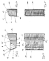
- FIG. 1 the structure of the container 8 provided in the transport vehicle according to FIG. 1 is shown in more detail.
- a stop 15 is provided on both sides of the position-changing section 10 of the container, which defines the position of the position-changing section 10 in the first position of the container by a vertical strut 16 of the fixed section 9 of the container embraces.
- the bottom 17 of the position-changing section 10 of the container assumes a vertical position; it forms the front side wall of the container in the second position.
- the actual opening opposite the bottom 17 of the position-changing section of the container, which in the first position of the container points upwards but in the second position backwards, is in the second position of the container through the rear side wall 14 of the fixed section 9 of the container covered.
- the front side wall 12 of the position-changing section 10 of the container is suspended in the region of the upper longitudinal edge 13, which runs transversely to the direction of travel, so that it can pivot about a horizontal axis 18. This enables the front side wall 12 to be pivoted into the interior of the position-changing section 10 of the container (arrow B). If the position-changing section 10 is pivoted about the axis 11 from the first position (FIGS. 2 and 3) to the second position (FIGS. 4 and 5) (arrow A), the front side wall 12 of the position-changing section 10 pivots due to the Gravity automatically into a position in which it is immediately adjacent to the rear wall 14 of the fixed portion 9 of the container.
- the space-saving collapsed container is easily accessible from above in its second position, because its opening pointing upward extends over the entire width and depth of the collapsed container. Also in the second position, the container is on all four sides through the bottom 17 and the side walls of the position-changing section 10 and the rear wall 14 of the fixed section 9 closed so that objects cannot fall out of it. If the container is brought from its second position into its first position (arrow C), the front side wall 12 of the position-changing section 10 of the container swings back automatically into its position shown in FIGS. 1, 2 and 3.
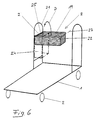
- the trolley shown in FIG. 6 is identical in its basic structure to the trolley according to German Offenlegungsschrift 34 05 154.
- the basket-like container 8 has a loop 19 on each of its two upper longitudinal edges running transversely to the direction of travel. These two loops 19 are guided on an axis 20 which extends horizontally in the direction of travel and one of the two brackets 21 is fastened between the two legs.
- the container 8 can be raised and brought into a space-saving vertical - shown in dash-dotted lines - second position (arrow D).
- German Offenlegungsschrift 34 05 154 the disclosure content of which is referred to in this respect.
- the side wall 22 of the container 8 which points upwards in the second position of the container, is pivotably suspended about a horizontal axis 23 running in the direction of travel. If the container is moved from its horizontal first position into the second position (shown in broken lines) (arrow D), the side wall 22 automatically pivots about the axis 23 into the interior of the container and in this way gives access to the container from above the second position free.
- the bottom of the The container opening opposite the container is closed in its second position by a wall 24 which is provided between the two legs of the bracket 21. That side wall 25 of the container, which lies opposite the pivotable side wall 22 and is adjacent to the bracket 21 in the first position of the container, forms the bottom thereof in the second position of the container.
Landscapes
- Engineering & Computer Science (AREA)
- Chemical & Material Sciences (AREA)
- Combustion & Propulsion (AREA)
- Transportation (AREA)
- Mechanical Engineering (AREA)
- Handcart (AREA)
- Multiple-Way Valves (AREA)
- Carriers, Traveling Bodies, And Overhead Traveling Cranes (AREA)
Applications Claiming Priority (2)
| Application Number | Priority Date | Filing Date | Title |
|---|---|---|---|
| DE4417418 | 1994-05-18 | ||
| DE4417418A DE4417418C2 (de) | 1994-05-18 | 1994-05-18 | Transportwagen |
Publications (3)
| Publication Number | Publication Date |
|---|---|
| EP0683083A2 true EP0683083A2 (fr) | 1995-11-22 |
| EP0683083A3 EP0683083A3 (fr) | 1996-11-20 |
| EP0683083B1 EP0683083B1 (fr) | 1999-03-10 |
Family
ID=6518390
Family Applications (1)
| Application Number | Title | Priority Date | Filing Date |
|---|---|---|---|
| EP95106969A Expired - Lifetime EP0683083B1 (fr) | 1994-05-18 | 1995-05-09 | Chariot de transport |
Country Status (4)
| Country | Link |
|---|---|
| EP (1) | EP0683083B1 (fr) |
| AT (1) | ATE177382T1 (fr) |
| DE (2) | DE4417418C2 (fr) |
| ES (1) | ES2131724T3 (fr) |
Families Citing this family (9)
| Publication number | Priority date | Publication date | Assignee | Title |
|---|---|---|---|---|
| DE29600565U1 (de) * | 1996-01-15 | 1996-03-07 | Wanzl Metallwarenfabrik Gmbh, 89340 Leipheim | Von Hand bewegbarer Transportwagen |
| DE19920185C1 (de) * | 1999-05-03 | 2000-07-13 | Siegel Geb Gmbh Co Kg | Transportwagen |
| DE10162007B4 (de) * | 2001-12-18 | 2004-07-01 | Brüder Siegel GmbH & Co KG Draht- und Metallwarenfabrik | Handbetätigter Transportwagen |
| DE10224840A1 (de) * | 2002-06-05 | 2003-12-24 | Wanzl Metallwarenfabrik Kg | Von Hand bewegbarer Transportwagen |
| DE10305194A1 (de) | 2003-01-07 | 2004-07-15 | Brüder Siegel GmbH & Co KG Draht- und Metallwarenfabrik | Stapelbarer Transportwagen |
| DE102007060983A1 (de) | 2007-12-14 | 2009-06-18 | Wanzl Metallwarenfabrik Gmbh | Transportwagen |
| DE102011010154A1 (de) * | 2011-02-02 | 2012-08-02 | Wanzl Metallwarenfabrik Gmbh | Stapelbarer Transportwagen |
| DE202013100947U1 (de) * | 2013-03-05 | 2014-06-06 | J. D. Geck Gmbh | Klappbares Einkaufswagenaufsatzelement zur Befestigung an einem stapelbaren Einkaufswagenkorb und stapelbarer Einkaufswagenkorb |
| CN113874273A (zh) * | 2019-04-03 | 2021-12-31 | Knap公司 | 用于对容器进行支撑和称重的推车 |
Citations (5)
| Publication number | Priority date | Publication date | Assignee | Title |
|---|---|---|---|---|
| DE340515C (de) | 1921-09-14 | Thomas Rozankovich | Rad mit Blattfederspeichen | |
| FR1423726A (fr) | 1964-09-23 | 1966-01-07 | Union Steel Prod Co | Poussette de magasin |
| US4560180A (en) | 1984-06-11 | 1985-12-24 | Whittar Industries, Ltd. | Shopping cart |
| DE3445685A1 (de) | 1984-02-14 | 1986-06-19 | Rudolf Wanzl Kg, 8874 Leipheim | Von hand bewegbarer transportwagen |
| EP0337043A1 (fr) | 1988-04-06 | 1989-10-18 | Ateliers Reunis Caddie | Chariot d'achat comportant une corbeille pivotante |
Family Cites Families (5)
| Publication number | Priority date | Publication date | Assignee | Title |
|---|---|---|---|---|
| US3245498A (en) * | 1963-09-24 | 1966-04-12 | Stanley | Supermarket cart |
| DE3402944A1 (de) * | 1984-01-28 | 1985-08-08 | Rudolf Wanzl Kg, 8874 Leipheim | Anordnung von zwei ablagen an zwei nach oben gerichteten traegern |
| DE3405154A1 (de) * | 1984-02-14 | 1985-08-22 | Rudolf Wanzl Kg, 8874 Leipheim | Transportwagen |
| DE8904507U1 (de) * | 1989-04-11 | 1989-11-09 | Wanzl GmbH & Co Entwicklungs KG, 8874 Leipheim | Von Hand bewegbarer Transportwagen |
| DE8908242U1 (de) * | 1989-07-06 | 1990-01-04 | Wanzl GmbH & Co Entwicklungs KG, 8874 Leipheim | Von Hand bewegbarer Transportwagen |
-
1994
- 1994-05-18 DE DE4417418A patent/DE4417418C2/de not_active Expired - Fee Related
-
1995
- 1995-05-09 ES ES95106969T patent/ES2131724T3/es not_active Expired - Lifetime
- 1995-05-09 EP EP95106969A patent/EP0683083B1/fr not_active Expired - Lifetime
- 1995-05-09 AT AT95106969T patent/ATE177382T1/de not_active IP Right Cessation
- 1995-05-09 DE DE59505240T patent/DE59505240D1/de not_active Expired - Lifetime
Patent Citations (5)
| Publication number | Priority date | Publication date | Assignee | Title |
|---|---|---|---|---|
| DE340515C (de) | 1921-09-14 | Thomas Rozankovich | Rad mit Blattfederspeichen | |
| FR1423726A (fr) | 1964-09-23 | 1966-01-07 | Union Steel Prod Co | Poussette de magasin |
| DE3445685A1 (de) | 1984-02-14 | 1986-06-19 | Rudolf Wanzl Kg, 8874 Leipheim | Von hand bewegbarer transportwagen |
| US4560180A (en) | 1984-06-11 | 1985-12-24 | Whittar Industries, Ltd. | Shopping cart |
| EP0337043A1 (fr) | 1988-04-06 | 1989-10-18 | Ateliers Reunis Caddie | Chariot d'achat comportant une corbeille pivotante |
Also Published As
| Publication number | Publication date |
|---|---|
| ES2131724T3 (es) | 1999-08-01 |
| DE4417418A1 (de) | 1995-06-01 |
| ATE177382T1 (de) | 1999-03-15 |
| EP0683083B1 (fr) | 1999-03-10 |
| DE4417418C2 (de) | 1998-03-12 |
| EP0683083A3 (fr) | 1996-11-20 |
| DE59505240D1 (de) | 1999-04-15 |
Similar Documents
| Publication | Publication Date | Title |
|---|---|---|
| DE2924658A1 (de) | Rollwagen | |
| DE8812023U1 (de) | Einkaufswagen mit einem an seinem oberen Teil angeordneten Transportkorb | |
| EP0141398B1 (fr) | Chariot à provisions encastrable | |
| EP0683083B1 (fr) | Chariot de transport | |
| DE8500639U1 (de) | Einkaufswagen für Selbstbedienungsläden mit einer Abstellvorrichtung für Kisten oder dgl. | |
| DE3231323A1 (de) | Einkaufswagen zur verwendung in verbindung mit kraftfahrzeugen | |
| DE102008031541A1 (de) | Zusammenklappbarer Transportwagen, insbesondere Einkaufswagen | |
| DE8508238U1 (de) | Stapelbarer Einkaufswagen | |
| DE8136236U1 (de) | Stapelbarer einkaufswagen | |
| EP0672569B1 (fr) | Chariot d'achat | |
| EP1104376A1 (fr) | Chariot transporteur empilable | |
| DE3444278C2 (de) | Stapelbarer Einkaufswagen | |
| DE2739291A1 (de) | Transportkarren oder -wagen | |
| EP0609663A1 (fr) | Chariot d'achats | |
| EP0798193B1 (fr) | Chariot d'achat emboítable | |
| DE29717107U1 (de) | Einkaufswagen und zusätzlicher Lastträger für einen solchen | |
| WO2005030556A2 (fr) | Chariot de supermarche | |
| DE8331746U1 (de) | Stapelbarer einkaufswagen | |
| DE3233291C2 (fr) | ||
| EP0738645B1 (fr) | Chariot d'achat emboitâble | |
| EP0685378B1 (fr) | Chariot d'achat emboítable | |
| EP0676323B1 (fr) | Chariot d'achat du type emboîtable | |
| EP1093988A1 (fr) | Chariot de transport | |
| EP0905004A2 (fr) | Chariot d'achat emboítable | |
| DE4033548A1 (de) | Einkaufswagen |
Legal Events
| Date | Code | Title | Description |
|---|---|---|---|
| PUAI | Public reference made under article 153(3) epc to a published international application that has entered the european phase |
Free format text: ORIGINAL CODE: 0009012 |
|
| AK | Designated contracting states |
Kind code of ref document: A2 Designated state(s): AT BE CH DE ES FR GB IT LI LU NL |
|
| PUAL | Search report despatched |
Free format text: ORIGINAL CODE: 0009013 |
|
| AK | Designated contracting states |
Kind code of ref document: A3 Designated state(s): AT BE CH DE ES FR GB IT LI LU NL |
|
| 17P | Request for examination filed |
Effective date: 19961015 |
|
| 17Q | First examination report despatched |
Effective date: 19980114 |
|
| GRAG | Despatch of communication of intention to grant |
Free format text: ORIGINAL CODE: EPIDOS AGRA |
|
| GRAG | Despatch of communication of intention to grant |
Free format text: ORIGINAL CODE: EPIDOS AGRA |
|
| GRAH | Despatch of communication of intention to grant a patent |
Free format text: ORIGINAL CODE: EPIDOS IGRA |
|
| GRAH | Despatch of communication of intention to grant a patent |
Free format text: ORIGINAL CODE: EPIDOS IGRA |
|
| GRAA | (expected) grant |
Free format text: ORIGINAL CODE: 0009210 |
|
| AK | Designated contracting states |
Kind code of ref document: B1 Designated state(s): AT BE CH DE ES FR GB IT LI LU NL |
|
| REF | Corresponds to: |
Ref document number: 177382 Country of ref document: AT Date of ref document: 19990315 Kind code of ref document: T |
|
| REG | Reference to a national code |
Ref country code: CH Ref legal event code: NV Representative=s name: ISLER & PEDRAZZINI AG Ref country code: CH Ref legal event code: EP |
|
| REF | Corresponds to: |
Ref document number: 59505240 Country of ref document: DE Date of ref document: 19990415 |
|
| ET | Fr: translation filed | ||
| ITF | It: translation for a ep patent filed | ||
| GBT | Gb: translation of ep patent filed (gb section 77(6)(a)/1977) |
Effective date: 19990607 |
|
| REG | Reference to a national code |
Ref country code: ES Ref legal event code: FG2A Ref document number: 2131724 Country of ref document: ES Kind code of ref document: T3 |
|
| PLBE | No opposition filed within time limit |
Free format text: ORIGINAL CODE: 0009261 |
|
| STAA | Information on the status of an ep patent application or granted ep patent |
Free format text: STATUS: NO OPPOSITION FILED WITHIN TIME LIMIT |
|
| 26N | No opposition filed | ||
| REG | Reference to a national code |
Ref country code: GB Ref legal event code: IF02 |
|
| PGFP | Annual fee paid to national office [announced via postgrant information from national office to epo] |
Ref country code: IT Payment date: 20060531 Year of fee payment: 12 |
|
| PGFP | Annual fee paid to national office [announced via postgrant information from national office to epo] |
Ref country code: BE Payment date: 20061122 Year of fee payment: 12 Ref country code: AT Payment date: 20061122 Year of fee payment: 12 |
|
| PGFP | Annual fee paid to national office [announced via postgrant information from national office to epo] |
Ref country code: CH Payment date: 20061123 Year of fee payment: 12 |
|
| PGFP | Annual fee paid to national office [announced via postgrant information from national office to epo] |
Ref country code: LU Payment date: 20061124 Year of fee payment: 12 |
|
| REG | Reference to a national code |
Ref country code: CH Ref legal event code: PCAR Free format text: ISLER & PEDRAZZINI AG;POSTFACH 1772;8027 ZUERICH (CH) |
|
| BERE | Be: lapsed |
Owner name: *BRUDER SIEGEL G.M.B.H. + CO. K.G. DRAHT- UND META Effective date: 20070531 |
|
| REG | Reference to a national code |
Ref country code: CH Ref legal event code: PL |
|
| PG25 | Lapsed in a contracting state [announced via postgrant information from national office to epo] |
Ref country code: AT Free format text: LAPSE BECAUSE OF NON-PAYMENT OF DUE FEES Effective date: 20070509 Ref country code: LI Free format text: LAPSE BECAUSE OF NON-PAYMENT OF DUE FEES Effective date: 20070531 Ref country code: CH Free format text: LAPSE BECAUSE OF NON-PAYMENT OF DUE FEES Effective date: 20070531 |
|
| PG25 | Lapsed in a contracting state [announced via postgrant information from national office to epo] |
Ref country code: BE Free format text: LAPSE BECAUSE OF NON-PAYMENT OF DUE FEES Effective date: 20070531 |
|
| REG | Reference to a national code |
Ref country code: GB Ref legal event code: 732E |
|
| PGFP | Annual fee paid to national office [announced via postgrant information from national office to epo] |
Ref country code: ES Payment date: 20080523 Year of fee payment: 14 |
|
| NLS | Nl: assignments of ep-patents |
Owner name: SIEWA METALLWARENFABRIK GMBH Effective date: 20080519 |
|
| NLT1 | Nl: modifications of names registered in virtue of documents presented to the patent office pursuant to art. 16 a, paragraph 1 |
Owner name: SIEGEL GMBH CO.KG. |
|
| PGFP | Annual fee paid to national office [announced via postgrant information from national office to epo] |
Ref country code: NL Payment date: 20080523 Year of fee payment: 14 |
|
| PGFP | Annual fee paid to national office [announced via postgrant information from national office to epo] |
Ref country code: GB Payment date: 20080522 Year of fee payment: 14 |
|
| PG25 | Lapsed in a contracting state [announced via postgrant information from national office to epo] |
Ref country code: LU Free format text: LAPSE BECAUSE OF NON-PAYMENT OF DUE FEES Effective date: 20070509 |
|
| PG25 | Lapsed in a contracting state [announced via postgrant information from national office to epo] |
Ref country code: IT Free format text: LAPSE BECAUSE OF NON-PAYMENT OF DUE FEES Effective date: 20070509 |
|
| GBPC | Gb: european patent ceased through non-payment of renewal fee |
Effective date: 20090509 |
|
| NLV4 | Nl: lapsed or anulled due to non-payment of the annual fee |
Effective date: 20091201 |
|
| PG25 | Lapsed in a contracting state [announced via postgrant information from national office to epo] |
Ref country code: NL Free format text: LAPSE BECAUSE OF NON-PAYMENT OF DUE FEES Effective date: 20091201 |
|
| REG | Reference to a national code |
Ref country code: FR Ref legal event code: ST Effective date: 20100129 |
|
| PG25 | Lapsed in a contracting state [announced via postgrant information from national office to epo] |
Ref country code: FR Free format text: LAPSE BECAUSE OF NON-PAYMENT OF DUE FEES Effective date: 20090602 |
|
| PGFP | Annual fee paid to national office [announced via postgrant information from national office to epo] |
Ref country code: FR Payment date: 20080519 Year of fee payment: 14 |
|
| PG25 | Lapsed in a contracting state [announced via postgrant information from national office to epo] |
Ref country code: GB Free format text: LAPSE BECAUSE OF NON-PAYMENT OF DUE FEES Effective date: 20090509 |
|
| REG | Reference to a national code |
Ref country code: ES Ref legal event code: FD2A Effective date: 20090511 |
|
| PG25 | Lapsed in a contracting state [announced via postgrant information from national office to epo] |
Ref country code: ES Free format text: LAPSE BECAUSE OF NON-PAYMENT OF DUE FEES Effective date: 20090511 |
|
| PGFP | Annual fee paid to national office [announced via postgrant information from national office to epo] |
Ref country code: DE Payment date: 20110531 Year of fee payment: 17 |
|
| REG | Reference to a national code |
Ref country code: DE Ref legal event code: R119 Ref document number: 59505240 Country of ref document: DE Effective date: 20121201 |
|
| PG25 | Lapsed in a contracting state [announced via postgrant information from national office to epo] |
Ref country code: DE Free format text: LAPSE BECAUSE OF NON-PAYMENT OF DUE FEES Effective date: 20121201 |