EP0683089B1 - Road vehicle with lowerable loading platform - Google Patents
Road vehicle with lowerable loading platform Download PDFInfo
- Publication number
- EP0683089B1 EP0683089B1 EP95107391A EP95107391A EP0683089B1 EP 0683089 B1 EP0683089 B1 EP 0683089B1 EP 95107391 A EP95107391 A EP 95107391A EP 95107391 A EP95107391 A EP 95107391A EP 0683089 B1 EP0683089 B1 EP 0683089B1
- Authority
- EP
- European Patent Office
- Prior art keywords
- road vehicle
- vehicle according
- feature
- piston rod
- chassis
- Prior art date
- Legal status (The legal status is an assumption and is not a legal conclusion. Google has not performed a legal analysis and makes no representation as to the accuracy of the status listed.)
- Expired - Lifetime
Links
- 238000007789 sealing Methods 0.000 claims description 4
- 239000006096 absorbing agent Substances 0.000 claims 1
- 230000035939 shock Effects 0.000 claims 1
- 238000010276 construction Methods 0.000 abstract description 6
- 238000013016 damping Methods 0.000 description 5
- 229910000831 Steel Inorganic materials 0.000 description 3
- 239000010959 steel Substances 0.000 description 3
- 230000000694 effects Effects 0.000 description 1
- 239000000725 suspension Substances 0.000 description 1
- 230000001360 synchronised effect Effects 0.000 description 1
Images


Classifications
-
- B—PERFORMING OPERATIONS; TRANSPORTING
- B60—VEHICLES IN GENERAL
- B60P—VEHICLES ADAPTED FOR LOAD TRANSPORTATION OR TO TRANSPORT, TO CARRY, OR TO COMPRISE SPECIAL LOADS OR OBJECTS
- B60P1/00—Vehicles predominantly for transporting loads and modified to facilitate loading, consolidating the load, or unloading
- B60P1/04—Vehicles predominantly for transporting loads and modified to facilitate loading, consolidating the load, or unloading with a tipping movement of load-transporting element
- B60P1/06—Vehicles predominantly for transporting loads and modified to facilitate loading, consolidating the load, or unloading with a tipping movement of load-transporting element actuated by mechanical gearing only
- B60P1/08—Vehicles predominantly for transporting loads and modified to facilitate loading, consolidating the load, or unloading with a tipping movement of load-transporting element actuated by mechanical gearing only with relative displacement of the wheel axles
-
- B—PERFORMING OPERATIONS; TRANSPORTING
- B60—VEHICLES IN GENERAL
- B60G—VEHICLE SUSPENSION ARRANGEMENTS
- B60G15/00—Resilient suspensions characterised by arrangement, location or type of combined spring and vibration damper, e.g. telescopic type
- B60G15/02—Resilient suspensions characterised by arrangement, location or type of combined spring and vibration damper, e.g. telescopic type having mechanical spring
- B60G15/04—Resilient suspensions characterised by arrangement, location or type of combined spring and vibration damper, e.g. telescopic type having mechanical spring and mechanical damper or dynamic damper
-
- B—PERFORMING OPERATIONS; TRANSPORTING
- B60—VEHICLES IN GENERAL
- B60G—VEHICLE SUSPENSION ARRANGEMENTS
- B60G3/00—Resilient suspensions for a single wheel
- B60G3/02—Resilient suspensions for a single wheel with a single pivoted arm
- B60G3/12—Resilient suspensions for a single wheel with a single pivoted arm the arm being essentially parallel to the longitudinal axis of the vehicle
- B60G3/14—Resilient suspensions for a single wheel with a single pivoted arm the arm being essentially parallel to the longitudinal axis of the vehicle the arm being rigid
-
- B—PERFORMING OPERATIONS; TRANSPORTING
- B60—VEHICLES IN GENERAL
- B60P—VEHICLES ADAPTED FOR LOAD TRANSPORTATION OR TO TRANSPORT, TO CARRY, OR TO COMPRISE SPECIAL LOADS OR OBJECTS
- B60P1/00—Vehicles predominantly for transporting loads and modified to facilitate loading, consolidating the load, or unloading
- B60P1/04—Vehicles predominantly for transporting loads and modified to facilitate loading, consolidating the load, or unloading with a tipping movement of load-transporting element
- B60P1/30—Vehicles predominantly for transporting loads and modified to facilitate loading, consolidating the load, or unloading with a tipping movement of load-transporting element in combination with another movement of the element
- B60P1/34—Vehicles predominantly for transporting loads and modified to facilitate loading, consolidating the load, or unloading with a tipping movement of load-transporting element in combination with another movement of the element the other movement being raising or lowering
-
- B—PERFORMING OPERATIONS; TRANSPORTING
- B62—LAND VEHICLES FOR TRAVELLING OTHERWISE THAN ON RAILS
- B62D—MOTOR VEHICLES; TRAILERS
- B62D21/00—Understructures, i.e. chassis frame on which a vehicle body may be mounted
- B62D21/18—Understructures, i.e. chassis frame on which a vehicle body may be mounted characterised by the vehicle type and not provided for in groups B62D21/02 - B62D21/17
- B62D21/20—Understructures, i.e. chassis frame on which a vehicle body may be mounted characterised by the vehicle type and not provided for in groups B62D21/02 - B62D21/17 trailer type, i.e. a frame specifically constructed for use in a non-powered vehicle
-
- B—PERFORMING OPERATIONS; TRANSPORTING
- B62—LAND VEHICLES FOR TRAVELLING OTHERWISE THAN ON RAILS
- B62D—MOTOR VEHICLES; TRAILERS
- B62D63/00—Motor vehicles or trailers not otherwise provided for
- B62D63/06—Trailers
Definitions
- the invention relates to road vehicles, in particular Trailer, with a loading area, the rear edge of which is up the ground can be lowered, according to the preamble of Claim 1.
- road vehicles in particular Trailer, with a loading area, the rear edge of which is up the ground can be lowered, according to the preamble of Claim 1.
- Such vehicles are in many variants known and customary.
- the present invention is based on the object Specify road vehicle of the type mentioned at the outset, which not only with the simplest construction and operation has a large ground clearance and a large stroke, but at the same time also improved driving characteristics having.
- the advantage of the present invention is that Independent suspension as this makes the large and heavy continuous axles in favor of short stub axles according to an advantageous development with the help of Bushings are stored in the frame chassis, not applicable.
- the main advantage for practice results from the Holding forks in the holding grooves when the loading area is raised retract the piston rods of the hydraulic cylinders and that Mechanically block the chassis in the driving position. This eliminates the need for hydraulic cylinders keep constantly under pressure or toggle-like To use constructions.
- the wheel handlebars cranked. This enables an improved Guidance.
- Ring springs are special construction elements, made from a package of profiled steel rings, that combine good spring properties with high friction values. Such a vehicle has outstanding Road driving properties.
- a similar spring damping effect can be done with the help of hollow rubber springs reach between the cylinder housing and a holding plate mounted on the piston rod be positioned. Hollow rubber springs have damping from 20 %.
- Frame chassis facilities provided for swap bodies. So there is the possibility of the trailer as needed with a loading platform, with a horse transport box and to equip such things more.
- FIG. 1 shows a plan view of a frame chassis 1, 1 ' of a trailer, the rear edge 22 up to the road is lowerable.
- the frame chassis 1, 1 ' is as such known welded together from steel pipes. At the front end you can see a drawbar 18.
- the trailer runs on four individually suspended wheels 5, at the end of each one by an axle stub 2 pivotable wheel handlebar 3 is attached.
- Drum or Disc brakes 17 enable the effective braking of the Trailer.
- a more stable, two-sided mounting of the stub axle 2 or the sockets 24 are reached by an extension the same up to the parallel frame tube 1 '.
- a Hydraulic cylinder 6 On a transverse frame tube 23 is a Hydraulic cylinder 6 attached. At the piston 7 is one Piston rod 8 movable with the help of a swivel joint 8 ' stored. A sealing sleeve 9, the wide end of which open cylinder end inside and its narrow end at the Piston rod 8 is fixed, prevents the ingress of Dirt in the cylinder 6.
- the free end of the piston rod 8 is on the axle lever 4 articulated.
- A is inserted into the piston rod 8
- Spring-damping combination 10 in the form of a so-called Ring spring 11 consisting of a set of specially profiled steel rings that have good spring properties and Connect high friction damping with each other.
- Fig. 2 shows the piston 7 of the hydraulic cylinder 6 in its extended position.
- the wheel 5 is lowered
- the loading area is in the driving position.
- a holding fork 13 which has been rotated 90 degrees for the sake of clarity is drawn.
- the piston rod 8 is mechanical blocked and the vehicle remains in the raised Driving position. If the fork 13 is pulled out again, swivels under the weight of the trailer the wheel control arm 3 counterclockwise upwards.
- the piston 7 in retracted the cylinder 6, the pivot joint 8 'for the movement adjustment ensures.
- wheel 5, control arm 3, axle lever 4 and Cylinder 6 are coordinated so that the Trailing edge 22 (Fig. 1) of the frame chassis 1 or Loading area can be lowered down to the road.
- a battery 19 carried on the frame chassis 1 feeds one electric hydraulic pump 20, which has hydraulic lines 21 communicates with the hydraulic cylinders 6.
- FIG. 1 shows the synchronous actuation of all holding forks 13 a lever linkage 14, which from one on the drawbar 18th arranged central operating lever 15 is operated.
- a Spring 16 ensures that actuating linkage 14 and Holding forks 13 automatically back to their normal position go back.
Landscapes
- Engineering & Computer Science (AREA)
- Mechanical Engineering (AREA)
- Transportation (AREA)
- Chemical & Material Sciences (AREA)
- Combustion & Propulsion (AREA)
- Vehicle Body Suspensions (AREA)
- Road Paving Structures (AREA)
- Fluid-Damping Devices (AREA)
- Axle Suspensions And Sidecars For Cycles (AREA)
Abstract
Description
Die Erfindung betrifft Straßenfahrzeuge, insbesondere
Anhänger, mit einer Ladefläche, deren Hinterkante bis auf
den Erdboden absenkbar ist, gemäß dem Oberbegriff des
Anspruchs 1. Derartige Fahrzeuge sind in vielen Varianten
bekannt und handelsüblich.The invention relates to road vehicles, in particular
Trailer, with a loading area, the rear edge of which is up
the ground can be lowered, according to the preamble of
Der vorliegenden Erfindung liegt die Aufgabe zugrunde, ein Straßenfahrzeug der eingangs genannten Art anzugeben, welches bei einfachster Konstruktion und Bedienung nicht nur eine große Bodenfreiheit und einen großen Hub besitzt, sondern gleichzeitig auch noch verbesserte Fahreigenschaften aufweist.The present invention is based on the object Specify road vehicle of the type mentioned at the outset, which not only with the simplest construction and operation has a large ground clearance and a large stroke, but at the same time also improved driving characteristics having.
Diese Aufgabe wird gelöst durch ein Straßenfahrzeug mit den
Merkmalen des Anspruchs 1.This problem is solved by a road vehicle with the
Features of
Vorteilhaft an der vorliegenden Erfindung ist die Einzelradaufhängung, da dadurch die großen und schweren durchgehenden Achsen Zugunsten von kurzen Achsstummeln, die gemäß einer vorteilhaften Weiterbildung mit Hilfe von Buchsen im Rahmenchassis gelagert sind, entfallen. Der wesentliche Vorteil für die Praxis resultiert jedoch aus den Haltegabeln, die bei angehobener Ladefläche in Haltenuten an den Kolbenstangen der Hydraulikzylinder einfahren und das Fahrgestell in der Fahrposition mechanisch blockieren. Dadurch entfällt die Notwendigkeit, die Hydraulikzylinder ständig unter Druck zu halten oder kniehebelartige Konstruktionen zu verwenden.The advantage of the present invention is that Independent suspension as this makes the large and heavy continuous axles in favor of short stub axles according to an advantageous development with the help of Bushings are stored in the frame chassis, not applicable. Of the However, the main advantage for practice results from the Holding forks in the holding grooves when the loading area is raised retract the piston rods of the hydraulic cylinders and that Mechanically block the chassis in the driving position. This eliminates the need for hydraulic cylinders keep constantly under pressure or toggle-like To use constructions.
Gemäß einer vorteilhaften Weiterbildung der Erfindung sind die Radlenker gekröpft. Dies ermöglicht eine verbesserte Spurführung. According to an advantageous development of the invention the wheel handlebars cranked. This enables an improved Guidance.
Da die Kolbenstange der Hubzylinder in der Fahrposition des Fahrzeugs durch die Haltegabeln mechanisch blockiert wird, muß die Feder-Dämpfer-Konstruktion zwischen Zylinder und Achshebel, genauer gesagt zwischen Haltenut und Achshebel, positioniert werden.Since the piston rod of the lifting cylinder in the driving position of the Vehicle is mechanically blocked by the holding forks, the spring-damper construction between the cylinder and Axle lever, more precisely between the holding groove and the axle lever, be positioned.
Aus Platzgründen empfiehlt sich eine Feder-Dämpfer-Konstruktion in Form einer sogenannten Ringfeder. Ringfedern sind spezielle Konstruktionselemente, hergestellt aus einem Paket von profilierten Stahlringen, die gute Federeigenschaften mit hohen Reibwerten verbinden. Ein solches Fahrzeug besitzt herausragende Straßenfahreigenschaften.One is recommended for reasons of space Spring damper construction in the form of a so-called Ring spring. Ring springs are special construction elements, made from a package of profiled steel rings, that combine good spring properties with high friction values. Such a vehicle has outstanding Road driving properties.
Eine ähnliche Feder-Dämpfungs-Wirkung läßt sich mit Hilfe von Gummi-Hohlfedern erreichen, die zwischen Zylindergehäuse und einem an der Kolbenstange montierten Halteteller positioniert werden. Gummi-Hohlfedern haben eine Dämpfung von 20 %.A similar spring damping effect can be done with the help of hollow rubber springs reach between the cylinder housing and a holding plate mounted on the piston rod be positioned. Hollow rubber springs have damping from 20 %.
Um das Eindringen von Schmutz in den Zylinder zu verhindern, dessen kolbenstangenseitiges Ende im Falle einer schwenkbaren Kolbenstange offen sein muß, empfiehlt sich die Verwendung einer Dichtmanschette zwischen Zylinder und Kolbenstange.To prevent dirt from entering the cylinder, its piston rod end in the case of a pivoting piston rod must be open, the Use a sealing sleeve between the cylinder and Piston rod.
Vorzugsweise handelt es sich um eine innenliegende Manschette, die besser gegen Beschädigung geschützt ist.It is preferably an internal one Cuff that is better protected against damage.
Vorteilhafterweise dient zur Betätigung der jedem Zylinder zugeordneten Haltegabeln ein zentral zu betätigendes Hebelgestänge.It is advantageously used to actuate each cylinder assigned holding forks a centrally operated Lever linkage.
Gemäß einer bevorzugten Weiterbildung der Erfindung sind am Rahmenchassis Einrichtungen für Wechselaufbauten vorgesehen. Es besteht so die Möglichkeit, den Anhänger je nach Bedarf mit einer Ladepritsche, mit einer Pferdetransportbox und dergleichen mehr auszurüsten.According to a preferred development of the invention Frame chassis facilities provided for swap bodies. So there is the possibility of the trailer as needed with a loading platform, with a horse transport box and to equip such things more.
Anhand der Zeichnung soll die Erfindung in Form eines Ausführungsbeispiels näher erläutert werden. Es zeigen
- Fig. 1
- eine Draufsicht auf einen Anhänger ohne Aufbau,
- Fig. 2
- ausschnittsweise eine vergrößerte Darstellung der für das Heben und Senken verantwortlichen Bauteile als Seitenansicht und
- Fig. 3
- ausschnittsweise einen Schnitt durch das Rahmenchassis gemäß Linie III-III in Fig. 1.
- Fig. 1
- a top view of a trailer without body,
- Fig. 2
- detail of an enlarged view of the components responsible for lifting and lowering as a side view and
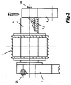
- Fig. 3
- a section of a section through the frame chassis according to line III-III in Fig. 1st
Fig. 1 zeigt eine Draufsicht auf ein Rahmenchassis 1, 1'
eines Anhängers, dessen Hinterkante 22 bis auf die Fahrbahn
absenkbar ist. Das Rahmenchassis 1, 1' ist wie an sich
bekannt aus Stahlrohren zusammengeschweißt. Am vorderen Ende
erkennt man eine Deichsel 18.1 shows a plan view of a
Der Anhänger fährt auf vier einzeln aufgehängten Rädern 5,
von denen jedes am Ende eines um einen Achsstummel 2
schwenkbaren Radlenkers 3 befestigt ist. Trommel- oder
Scheibenbremsen 17 ermöglichen das effektive Abbremsen des
Anhängers.The trailer runs on four individually suspended
Die Fig. 2 und 3 zeigen als ausschnittsweise Seitenansicht
bzw. als Schnitt die zum Heben und Senken verantwortlichen
Fahrzeugteile. Man erkennt den Achsstummel 2, der in einer
Buchse 24, die mit dem Rahmenchassis 1 verschweißt ist,
drehbar gelagert ist. Am äußeren Ende des Achsstummels 2 ist
der Radlenker 3, am inneren Ende ein Achshebel 4
angeschraubt, und zwar mit Hilfe von Schrauben 25 bzw. 26.2 and 3 show a partial side view
or as a cut those responsible for lifting and lowering
Car parts. One recognizes the
Eine stabilere, zweiseitige Lagerung der Achsstummel 2 bzw.
der Buchsen 24 erreicht man durch eine Verlängerung
derselben bis zum parallellaufenden Rahmenrohr 1'.A more stable, two-sided mounting of the
An einem querliegenden Rahmenrohr 23 ist ein
Hydraulikzylinder 6 befestigt. An dessen Kolben 7 ist eine
Kolbenstange 8 mit Hilfe eines Schwenkgelenks 8' beweglich
gelagert. Eine Dichtmanschette 9, deren weites Ende am
offenen Zylinderende innen und deren enges Ende an der
Kolbenstange 8 befestigt ist, verhindert das Eindringen von
Schmutz in den Zylinder 6.On a
Das freie Ende der Kolbenstange 8 ist am Achshebel 4
angelenkt. In die Kolbenstange 8 eingesetzt ist eine
Feder-Dämpfungs-Kombination 10 in Form einer sogenannten
Ringfeder 11, bestehend aus einem Satz von speziell
profilierten Stahlringen, die gute Federeigenschaften und
hohe Reibungsdämpfung miteinander verbinden.The free end of the
Fig. 2 zeigt den Kolben 7 des Hydraulikzylinders 6 in seiner
ausgefahrenen Position. Das Rad 5 ist abgesenkt, die
Ladefläche befindet sich in der Fahrposition. Man erkennt
zwischen dem Ende des Zylinders 6 und dem benachbarten Ende
der Feder-Dämpfungs-Kombination 10 eine Haltenut 12 im
Bereich der Kolbenstange 8. Zur Verriegelung der
Kolbenstange 8 in dieser Position dient eine Haltegabel 13,
die zwecks besserer Darstellung um 90 Grad gedreht
gezeichnet ist. Sobald die Haltegabel 13 in die Haltenut 12
eingefahren wird, ist die Kolbenstange 8 mechanisch
blockiert und das Fahrzeug bleibt in der angehobenen
Fahrposition. Wird die Gabel 13 wieder herausgezogen,
schwenkt unter dem Gewicht des Anhägers der Radlenker 3
gegen den Uhrzeiger nach oben. Dabei wird der Kolben 7 in
den Zylinder 6 eingefahren, wobei das Schwenkgelenk 8' für
die Bewegungsanpassung sorgt.Fig. 2 shows the
Die Abmessungen von Rad 5, Radlenker 3, Achshebel 4 und
Zylinder 6 sind so aufeinander abgestimmt, daß die
Hinterkante 22 (Fig. 1) des Rahmenchassis 1 bzw. der
Ladefläche bis auf die Fahrbahn abgesenkt werden können.
Eine am Rahmenchassis 1 mitgeführte Batterie 19 speist eine
elektrische Hydraulikpumpe 20, die über Hydraulikleitungen
21 mit den Hydraulikzylindern 6 in Verbindung steht.The dimensions of
Zur synchronen Betätigung aller Haltegabeln 13 zeigt Fig. 1
ein Hebelgestänge 14, welches von einem an der Deichsel 18
angeordneten zentralen Bedienhebel 15 betätigt wird. Eine
Feder 16 sorgt dafür, daß Betätigungsgestänge 14 und
Haltegabeln 13 selbsttätig wieder in ihre Grundstellung
zurückgehen.1 shows the synchronous actuation of all holding forks 13
a
Zur Befestigung von Wechselaufbauten, beispielsweise in Form
von Ladepritschen, Pferdetransportboxen usw., können an dem
Rahmenchassis 1 entsprechende Befestigungsvorrichtungen
vorgesehen werden, wie sie aus dem Stand der Technik bekannt
sind.For attaching swap bodies, for example in form
of loading platforms, horse transport boxes, etc. can be attached to the
Claims (10)
- A road vehicle, in particular a trailer, having a loading area, the rear edge of which can be lowered down to the ground, comprisinga chassis frame (1,1')at least two axles (2) mounted on the chassis (1,1'),a wheel link (3) and an axle member (4) on each axle (2),a wheel (5) at the end of each wheel link (3),a hydraulic cylinder (6) with a piston (7) and a piston rod (8) between the chassis (1,1') and each axle member (4),and at least one shock absorber, further comprising the features that:the wheels (5) are independently suspended,the axles (3) are formed as stub axles,
characterised by the features that:a spring-damper assembly (10) is mounted between the cylinder (6) and the axle member (4),the piston rod (8) is provided with a retaining recess (12),and at least one retaining fork (13) is mounted on the chassis (1),-- which registers with the retaining recess (12)-- and mechanically locks the piston rod (8) when the wheels (5) are lowered. - A road vehicle according to Claim 1, characterised by the feature that:the wheel links (3) are cranked.
- A road vehicle according to Claim 1 or 2, characterised by the feature that:the stub axles (2) are mounted at each end on two portions extending parallel from the frame (1,1').
- A road vehicle according to Claim 1, 2 or 3, characterised by the feature that:the stub axles (2) are mounted to rotate on the chassis (1,1') in bushes (24).
- A road vehicle according to any of Claims 1 to 4, characterised by the feature that:the spring-damper assembly (10) is in the form of an annular spring (11).
- A road vehicle according to any one of Claims 1 to 4, characterised by the feature that:the spring-damper assembly (10) is in the form of a rubber hollow spring.
- A road vehicle according to any one of Claims 1 to 6, characterised by the feature that:the piston rod (8) is pivotably mounted on the piston (7),a sealing sleeve (9) between the cylinder (6) and the piston rod (8) prevents the ingress of dirt.
- A road vehicle according to Claim 7, characterised by the feature that:the sealing sleeve (9) is accommodated with protection in the cylinder (6).
- A road vehicle according to any one of Claims 1 to 8, characterised by the features that:a retaining fork (13) is associated with each cylinder (6),all the retaining forks (13) are intended to be actuated centrally via lever a linkage (14,15).
- A road vehicle according to Claim 1, characterised by the feature that:fastening means for interchangeable superstructures are provided on the chassis frame (1,1')
Applications Claiming Priority (2)
| Application Number | Priority Date | Filing Date | Title |
|---|---|---|---|
| DE9408076U | 1994-05-17 | ||
| DE9408076U DE9408076U1 (en) | 1994-05-17 | 1994-05-17 | Road vehicle with lowerable loading area |
Publications (2)
| Publication Number | Publication Date |
|---|---|
| EP0683089A1 EP0683089A1 (en) | 1995-11-22 |
| EP0683089B1 true EP0683089B1 (en) | 1998-02-04 |
Family
ID=6908714
Family Applications (1)
| Application Number | Title | Priority Date | Filing Date |
|---|---|---|---|
| EP95107391A Expired - Lifetime EP0683089B1 (en) | 1994-05-17 | 1995-05-16 | Road vehicle with lowerable loading platform |
Country Status (4)
| Country | Link |
|---|---|
| EP (1) | EP0683089B1 (en) |
| AT (1) | ATE162985T1 (en) |
| DE (2) | DE9408076U1 (en) |
| ES (1) | ES2115290T3 (en) |
Cited By (1)
| Publication number | Priority date | Publication date | Assignee | Title |
|---|---|---|---|---|
| DE10221870A1 (en) * | 2002-05-15 | 2003-12-04 | Fahrzeugteile Service Zentrum | Vehicle trailer and wheel suspension for a vehicle trailer |
Families Citing this family (3)
| Publication number | Priority date | Publication date | Assignee | Title |
|---|---|---|---|---|
| DE29621355U1 (en) * | 1996-12-10 | 1998-04-09 | Bremer, Dieter, 38315 Schladen | Vehicle trailer |
| GB2351478A (en) | 1999-06-30 | 2001-01-03 | Michael Owen James Benton | An adjustable trailer. |
| CN116461612B (en) * | 2023-05-06 | 2025-08-22 | 重庆军通汽车有限责任公司 | A loading platform trailer |
Family Cites Families (6)
| Publication number | Priority date | Publication date | Assignee | Title |
|---|---|---|---|---|
| DE873939C (en) * | 1951-02-24 | 1953-04-20 | Henschel & Sohn G M B H | Oil pressure cylinder for regulating the suspension for motor vehicles |
| US3199890A (en) * | 1963-06-21 | 1965-08-10 | Everette V Caldwell | Wheel mounting |
| GB1124791A (en) * | 1965-02-26 | 1968-08-21 | Maurice Raymond Green | Improvements in retractible suspensions for vehicle wheels |
| DE2938518A1 (en) * | 1979-09-24 | 1981-04-09 | Fritz 4270 Dorsten Schmidt | Trailer with lowering suspension - has mechanical lock for raised setting |
| DE3637387A1 (en) * | 1986-11-03 | 1988-05-05 | Sieben Hans Hermann | Wheel suspension for lowerable vehicle bodies |
| DE9404769U1 (en) * | 1994-03-21 | 1994-05-19 | Straub, Manfred, 88094 Oberteuringen | Lowerable chassis, especially for trailers |
-
1994
- 1994-05-17 DE DE9408076U patent/DE9408076U1/en not_active Expired - Lifetime
-
1995
- 1995-05-16 EP EP95107391A patent/EP0683089B1/en not_active Expired - Lifetime
- 1995-05-16 ES ES95107391T patent/ES2115290T3/en not_active Expired - Lifetime
- 1995-05-16 AT AT95107391T patent/ATE162985T1/en not_active IP Right Cessation
- 1995-05-16 DE DE59501394T patent/DE59501394D1/en not_active Expired - Fee Related
Cited By (2)
| Publication number | Priority date | Publication date | Assignee | Title |
|---|---|---|---|---|
| DE10221870A1 (en) * | 2002-05-15 | 2003-12-04 | Fahrzeugteile Service Zentrum | Vehicle trailer and wheel suspension for a vehicle trailer |
| DE10221870B4 (en) * | 2002-05-15 | 2006-06-29 | Fahrzeugteile Service-Zentrum Mellendorf Gmbh | car trailers |
Also Published As
| Publication number | Publication date |
|---|---|
| EP0683089A1 (en) | 1995-11-22 |
| ATE162985T1 (en) | 1998-02-15 |
| DE59501394D1 (en) | 1998-03-12 |
| DE9408076U1 (en) | 1994-07-14 |
| ES2115290T3 (en) | 1998-06-16 |
Similar Documents
| Publication | Publication Date | Title |
|---|---|---|
| DE69934671T2 (en) | ADJUSTABLE VEHICLE MOUNT | |
| DE3302998C2 (en) | Wheel suspension for wheels or wheel axles that can be swiveled into the vehicle body | |
| DE2546485C3 (en) | Road vehicle with lowerable loading area | |
| DE102012205641A1 (en) | Heavy duty trailer with MacPherson independent suspension | |
| DE2101504B2 (en) | Height and track width variable independent wheel suspension for a mobile work machine | |
| EP0237619B1 (en) | Wheel suspension for vehicle superstructures which can be lowered, especially for trailers, front drive trucks (dormobiles), caravans | |
| DE3743203A1 (en) | Wheel-guide unit | |
| DE1630774B2 (en) | VEHICLE FOR TRANSPORTING PARTICULARLY HEAVY LOADS ABOUT THE VEHICLE WIDTH | |
| EP0332037A2 (en) | Axle lifting device | |
| DE3228829A1 (en) | Loading device for superstructures of lorries | |
| DE102008006119B3 (en) | Mobile crane has upper structure, on which boom is hinged to teeter around horizontal axis, and cabin that is provided for crane operator, which is arranged on upper structure pivoting over sluing mechanism | |
| DE3637387A1 (en) | Wheel suspension for lowerable vehicle bodies | |
| EP0683089A1 (en) | Road vehicle with lowerable loading platform | |
| DE2837398A1 (en) | Self-propelled crane for heavy loads - has steerable multi-axle trailer to carry rear outrigger support legs | |
| DE19607945A1 (en) | Container for exchangeable mounting and transfer | |
| DE19728822B4 (en) | Cultivation trailing suspension | |
| DE3010483C2 (en) | Rear support cylinders on a transport vehicle | |
| DE3532006C2 (en) | ||
| DE3531853A1 (en) | Loading device on the superstructures of lorries | |
| DE19506930C2 (en) | Device for lowering the rear part of a vehicle to bring it close to the ground | |
| EP2711211B1 (en) | Wheel suspension for a heavy duty transport vehicle and heavy duty transport vehicle using such a wheel suspension | |
| DE3527935A1 (en) | Loading device for the superstructures of lorries | |
| DE2938518A1 (en) | Trailer with lowering suspension - has mechanical lock for raised setting | |
| DE10217155A1 (en) | Recovery trailer is constructed as independent mobile unit equipped with at least one wheelset connected to rigid frame of trailer with height adjustment | |
| DE1247875B (en) | Transport vehicle for heavy loads |
Legal Events
| Date | Code | Title | Description |
|---|---|---|---|
| PUAI | Public reference made under article 153(3) epc to a published international application that has entered the european phase |
Free format text: ORIGINAL CODE: 0009012 |
|
| AK | Designated contracting states |
Kind code of ref document: A1 Designated state(s): AT BE CH DE DK ES FR GB GR IE IT LI LU MC NL PT SE |
|
| 17P | Request for examination filed |
Effective date: 19951214 |
|
| GRAG | Despatch of communication of intention to grant |
Free format text: ORIGINAL CODE: EPIDOS AGRA |
|
| 17Q | First examination report despatched |
Effective date: 19961114 |
|
| GRAH | Despatch of communication of intention to grant a patent |
Free format text: ORIGINAL CODE: EPIDOS IGRA |
|
| GRAH | Despatch of communication of intention to grant a patent |
Free format text: ORIGINAL CODE: EPIDOS IGRA |
|
| GRAA | (expected) grant |
Free format text: ORIGINAL CODE: 0009210 |
|
| AK | Designated contracting states |
Kind code of ref document: B1 Designated state(s): AT BE CH DE DK ES FR GB GR IE IT LI LU MC NL PT SE |
|
| PG25 | Lapsed in a contracting state [announced via postgrant information from national office to epo] |
Ref country code: NL Free format text: LAPSE BECAUSE OF FAILURE TO SUBMIT A TRANSLATION OF THE DESCRIPTION OR TO PAY THE FEE WITHIN THE PRESCRIBED TIME-LIMIT Effective date: 19980204 Ref country code: GR Free format text: LAPSE BECAUSE OF FAILURE TO SUBMIT A TRANSLATION OF THE DESCRIPTION OR TO PAY THE FEE WITHIN THE PRESCRIBED TIME-LIMIT Effective date: 19980204 |
|
| REF | Corresponds to: |
Ref document number: 162985 Country of ref document: AT Date of ref document: 19980215 Kind code of ref document: T |
|
| REG | Reference to a national code |
Ref country code: CH Ref legal event code: EP |
|
| REF | Corresponds to: |
Ref document number: 59501394 Country of ref document: DE Date of ref document: 19980312 |
|
| ITF | It: translation for a ep patent filed | ||
| PG25 | Lapsed in a contracting state [announced via postgrant information from national office to epo] |
Ref country code: SE Free format text: LAPSE BECAUSE OF FAILURE TO SUBMIT A TRANSLATION OF THE DESCRIPTION OR TO PAY THE FEE WITHIN THE PRESCRIBED TIME-LIMIT Effective date: 19980504 Ref country code: PT Free format text: LAPSE BECAUSE OF FAILURE TO SUBMIT A TRANSLATION OF THE DESCRIPTION OR TO PAY THE FEE WITHIN THE PRESCRIBED TIME-LIMIT Effective date: 19980504 Ref country code: DK Free format text: LAPSE BECAUSE OF FAILURE TO SUBMIT A TRANSLATION OF THE DESCRIPTION OR TO PAY THE FEE WITHIN THE PRESCRIBED TIME-LIMIT Effective date: 19980504 |
|
| PG25 | Lapsed in a contracting state [announced via postgrant information from national office to epo] |
Ref country code: LU Free format text: LAPSE BECAUSE OF NON-PAYMENT OF DUE FEES Effective date: 19980516 |
|
| GBT | Gb: translation of ep patent filed (gb section 77(6)(a)/1977) |
Effective date: 19980506 |
|
| REG | Reference to a national code |
Ref country code: CH Ref legal event code: NV Representative=s name: PATENTANWAELTE SCHAAD, BALASS, MENZL & PARTNER AG |
|
| PG25 | Lapsed in a contracting state [announced via postgrant information from national office to epo] |
Ref country code: BE Free format text: LAPSE BECAUSE OF NON-PAYMENT OF DUE FEES Effective date: 19980531 |
|
| ET | Fr: translation filed | ||
| REG | Reference to a national code |
Ref country code: ES Ref legal event code: FG2A Ref document number: 2115290 Country of ref document: ES Kind code of ref document: T3 |
|
| NLV1 | Nl: lapsed or annulled due to failure to fulfill the requirements of art. 29p and 29m of the patents act | ||
| REG | Reference to a national code |
Ref country code: IE Ref legal event code: FG4D Free format text: 78793 |
|
| PG25 | Lapsed in a contracting state [announced via postgrant information from national office to epo] |
Ref country code: IE Free format text: LAPSE BECAUSE OF NON-PAYMENT OF DUE FEES Effective date: 19980924 |
|
| REG | Reference to a national code |
Ref country code: IE Ref legal event code: FD4D Ref document number: 78793 Country of ref document: IE |
|
| BERE | Be: lapsed |
Owner name: MONTHERO CARLYLE Effective date: 19980531 |
|
| PG25 | Lapsed in a contracting state [announced via postgrant information from national office to epo] |
Ref country code: MC Free format text: LAPSE BECAUSE OF NON-PAYMENT OF DUE FEES Effective date: 19981130 |
|
| PLBE | No opposition filed within time limit |
Free format text: ORIGINAL CODE: 0009261 |
|
| STAA | Information on the status of an ep patent application or granted ep patent |
Free format text: STATUS: NO OPPOSITION FILED WITHIN TIME LIMIT |
|
| 26N | No opposition filed | ||
| REG | Reference to a national code |
Ref country code: GB Ref legal event code: IF02 |
|
| PGFP | Annual fee paid to national office [announced via postgrant information from national office to epo] |
Ref country code: FR Payment date: 20020329 Year of fee payment: 8 |
|
| PGFP | Annual fee paid to national office [announced via postgrant information from national office to epo] |
Ref country code: ES Payment date: 20020402 Year of fee payment: 8 |
|
| PGFP | Annual fee paid to national office [announced via postgrant information from national office to epo] |
Ref country code: CH Payment date: 20020403 Year of fee payment: 8 |
|
| PGFP | Annual fee paid to national office [announced via postgrant information from national office to epo] |
Ref country code: GB Payment date: 20020507 Year of fee payment: 8 |
|
| PGFP | Annual fee paid to national office [announced via postgrant information from national office to epo] |
Ref country code: AT Payment date: 20020514 Year of fee payment: 8 |
|
| PG25 | Lapsed in a contracting state [announced via postgrant information from national office to epo] |
Ref country code: GB Free format text: LAPSE BECAUSE OF NON-PAYMENT OF DUE FEES Effective date: 20030516 Ref country code: AT Free format text: LAPSE BECAUSE OF NON-PAYMENT OF DUE FEES Effective date: 20030516 |
|
| PG25 | Lapsed in a contracting state [announced via postgrant information from national office to epo] |
Ref country code: ES Free format text: LAPSE BECAUSE OF NON-PAYMENT OF DUE FEES Effective date: 20030517 |
|
| PG25 | Lapsed in a contracting state [announced via postgrant information from national office to epo] |
Ref country code: LI Free format text: LAPSE BECAUSE OF NON-PAYMENT OF DUE FEES Effective date: 20030531 Ref country code: CH Free format text: LAPSE BECAUSE OF NON-PAYMENT OF DUE FEES Effective date: 20030531 |
|
| GBPC | Gb: european patent ceased through non-payment of renewal fee |
Effective date: 20030516 |
|
| REG | Reference to a national code |
Ref country code: CH Ref legal event code: PL |
|
| PG25 | Lapsed in a contracting state [announced via postgrant information from national office to epo] |
Ref country code: FR Free format text: LAPSE BECAUSE OF NON-PAYMENT OF DUE FEES Effective date: 20040130 |
|
| REG | Reference to a national code |
Ref country code: FR Ref legal event code: ST |
|
| REG | Reference to a national code |
Ref country code: ES Ref legal event code: FD2A Effective date: 20030517 |
|
| PG25 | Lapsed in a contracting state [announced via postgrant information from national office to epo] |
Ref country code: IT Free format text: LAPSE BECAUSE OF NON-PAYMENT OF DUE FEES;WARNING: LAPSES OF ITALIAN PATENTS WITH EFFECTIVE DATE BEFORE 2007 MAY HAVE OCCURRED AT ANY TIME BEFORE 2007. THE CORRECT EFFECTIVE DATE MAY BE DIFFERENT FROM THE ONE RECORDED. Effective date: 20050516 |
|
| PGFP | Annual fee paid to national office [announced via postgrant information from national office to epo] |
Ref country code: DE Payment date: 20080528 Year of fee payment: 14 |
|
| PG25 | Lapsed in a contracting state [announced via postgrant information from national office to epo] |
Ref country code: DE Free format text: LAPSE BECAUSE OF NON-PAYMENT OF DUE FEES Effective date: 20091201 |