EP0683098B1 - Système de détermination de l'attitude d'un engin spatial utilisant un capteur solaire, un senseur de terre et une liaison terre-espace - Google Patents
Système de détermination de l'attitude d'un engin spatial utilisant un capteur solaire, un senseur de terre et une liaison terre-espace Download PDFInfo
- Publication number
- EP0683098B1 EP0683098B1 EP95107371A EP95107371A EP0683098B1 EP 0683098 B1 EP0683098 B1 EP 0683098B1 EP 95107371 A EP95107371 A EP 95107371A EP 95107371 A EP95107371 A EP 95107371A EP 0683098 B1 EP0683098 B1 EP 0683098B1
- Authority
- EP
- European Patent Office
- Prior art keywords
- spacecraft
- sensor
- attitude
- sgl
- sun
- Prior art date
- Legal status (The legal status is an assumption and is not a legal conclusion. Google has not performed a legal analysis and makes no representation as to the accuracy of the status listed.)
- Expired - Lifetime
Links
- 238000005259 measurement Methods 0.000 claims description 83
- 238000004891 communication Methods 0.000 claims description 22
- 238000000034 method Methods 0.000 claims description 20
- 238000011217 control strategy Methods 0.000 description 8
- 230000008878 coupling Effects 0.000 description 6
- 238000010168 coupling process Methods 0.000 description 6
- 238000005859 coupling reaction Methods 0.000 description 6
- 238000013461 design Methods 0.000 description 5
- 230000000694 effects Effects 0.000 description 4
- 238000000926 separation method Methods 0.000 description 4
- 238000010586 diagram Methods 0.000 description 3
- 230000003321 amplification Effects 0.000 description 2
- 230000008901 benefit Effects 0.000 description 2
- 230000008859 change Effects 0.000 description 2
- 238000003199 nucleic acid amplification method Methods 0.000 description 2
- 238000010561 standard procedure Methods 0.000 description 2
- 238000012546 transfer Methods 0.000 description 2
- 238000009825 accumulation Methods 0.000 description 1
- 230000009471 action Effects 0.000 description 1
- 230000000295 complement effect Effects 0.000 description 1
- 238000007796 conventional method Methods 0.000 description 1
- 238000001914 filtration Methods 0.000 description 1
- 230000006872 improvement Effects 0.000 description 1
- 238000013507 mapping Methods 0.000 description 1
- 230000035945 sensitivity Effects 0.000 description 1
- 230000003595 spectral effect Effects 0.000 description 1
Images

Classifications
-
- B—PERFORMING OPERATIONS; TRANSPORTING
- B64—AIRCRAFT; AVIATION; COSMONAUTICS
- B64G—COSMONAUTICS; VEHICLES OR EQUIPMENT THEREFOR
- B64G1/00—Cosmonautic vehicles
- B64G1/22—Parts of, or equipment specially adapted for fitting in or to, cosmonautic vehicles
- B64G1/24—Guiding or controlling apparatus, e.g. for attitude control
- B64G1/28—Guiding or controlling apparatus, e.g. for attitude control using inertia or gyro effect
- B64G1/285—Guiding or controlling apparatus, e.g. for attitude control using inertia or gyro effect using momentum wheels
-
- B—PERFORMING OPERATIONS; TRANSPORTING
- B64—AIRCRAFT; AVIATION; COSMONAUTICS
- B64G—COSMONAUTICS; VEHICLES OR EQUIPMENT THEREFOR
- B64G1/00—Cosmonautic vehicles
- B64G1/22—Parts of, or equipment specially adapted for fitting in or to, cosmonautic vehicles
- B64G1/24—Guiding or controlling apparatus, e.g. for attitude control
- B64G1/244—Spacecraft control systems
- B64G1/245—Attitude control algorithms for spacecraft attitude control
-
- B—PERFORMING OPERATIONS; TRANSPORTING
- B64—AIRCRAFT; AVIATION; COSMONAUTICS
- B64G—COSMONAUTICS; VEHICLES OR EQUIPMENT THEREFOR
- B64G1/00—Cosmonautic vehicles
- B64G1/22—Parts of, or equipment specially adapted for fitting in or to, cosmonautic vehicles
- B64G1/24—Guiding or controlling apparatus, e.g. for attitude control
- B64G1/36—Guiding or controlling apparatus, e.g. for attitude control using sensors, e.g. sun-sensors, horizon sensors
- B64G1/363—Guiding or controlling apparatus, e.g. for attitude control using sensors, e.g. sun-sensors, horizon sensors using sun sensors
-
- B—PERFORMING OPERATIONS; TRANSPORTING
- B64—AIRCRAFT; AVIATION; COSMONAUTICS
- B64G—COSMONAUTICS; VEHICLES OR EQUIPMENT THEREFOR
- B64G1/00—Cosmonautic vehicles
- B64G1/22—Parts of, or equipment specially adapted for fitting in or to, cosmonautic vehicles
- B64G1/24—Guiding or controlling apparatus, e.g. for attitude control
- B64G1/36—Guiding or controlling apparatus, e.g. for attitude control using sensors, e.g. sun-sensors, horizon sensors
- B64G1/365—Guiding or controlling apparatus, e.g. for attitude control using sensors, e.g. sun-sensors, horizon sensors using horizon or Earth sensors
-
- B—PERFORMING OPERATIONS; TRANSPORTING
- B64—AIRCRAFT; AVIATION; COSMONAUTICS
- B64G—COSMONAUTICS; VEHICLES OR EQUIPMENT THEREFOR
- B64G3/00—Observing or tracking cosmonautic vehicles
Definitions
- This invention relates to a spacecraft having a system for determining a three-axis attitude measurement, particularly a yaw attitude measurement of a spacecraft, and to a corresponding method.
- Spacecraft such as satellites employ a number of sensors to determine their relative orientation in space.
- An accurate indication of the spacecraft orientation is important for properly controlling the positioning of various spacecraft components, such as solar wings or communication antennas.
- spacecraft attitude measurements characterize spacecraft orientation relative to the pitch, roll, and yaw axes of the spacecraft.
- the spacecraft orientation measurements may be indicated directly by appropriate sensors or derived indirectly from those sensors.
- Momentum bias spacecraft utilize a momentum wheel which, typically, spins about the pitch axis so as to create a momentum bias nominally along that axis.
- This momentum bias provides "gyroscopic stiffness" to resist roll and yaw axis disturbance tories which attempt to perturb the spacecraft pitch axis from orbit normal.
- a larger momentum bias provides greater gyroscopic stiffness but also makes controlling the spacecraft more difficult.
- the gyroscopic effect also couples the roll and yaw dynamics.
- Prior art spacecraft control systems have recognized and utilized this coupling to control both the roll and yaw axes while directly sensing only the roll axis and deriving a yaw measurement from the roll sensor.
- the efficacy of this control strategy is proportional to the magnitude of the momentum bias.
- a relatively small momentum bias typically 20-80 N-m-sec on a geosynchronous communications satellite
- the yaw attitude cannot be controlled very accurately.
- geosynchronous momentum bias satellites do not have a device for direct measurement of the satellite yaw attitude. Instead, these satellites utilize the control strategy described above to derive a yaw attitude measurement from a roll sensor. The derived yaw attitude measurement is then utilized by the control system to properly position the satellite or its components. For example, the derived yaw attitude measurement may be used to point a satellite communication antenna toward a predetermined target.
- this control strategy requires a compromise between the size of the momentum bias and the accuracy of the spacecraft pointing, this system typically has limited accuracy and is sensitive to significantly large time-varying disturbance torques. Such a system is inadequate for use in a data relay spacecraft with large slewing antennas which experiences large time-varying disturbances due to the antenna slews, and the like. These applications require accurate yaw pointing in order to provide antenna pointing service to target locations which are off Earth nadir.
- the analog sun sensors are typically mounted on the solar wings of the spacecraft. These sun sensors provide a coarse yaw measurement during a large portion of the day, while an Earth sensor provides roll and pitch measurements. However, due to their location on the solar wings, the analog sun sensors are subject to bias and distortions. More importantly, near solar equinox, there are periods spanning close to two hours occurring twice daily when no yaw measurement is available. This occurs because, during those periods, the line from the spacecraft to the sun is nearly along the spacecraft yaw axis.
- the standard architecture for NASA's low-Earth-orbit mapping satellites includes a digital sun sensor.
- the digital sun sensor is typically a redundant component which functions only as a backup in case one of the two star sensors fails.
- a spacecraft having a system for determining a three-axis attitude measurement of the spacecraft, the spacecraft including a spacecraft body having pitch, roll, and yaw axes, means for receiving signals indicative of spacecraft operating conditions, a processor for generating command signals for controlling the spacecraft, an Earth sensor disposed within the spacecraft body for creating attitude reference signals indicative of a roll-axis attitude and a pitch-axis attitude, the Earth sensor being in communication with the processor, means for generating error signals indicative of an azimuth attitude error and an elevation attitude error with respect to at least one target ground station, the generating means being disposed within the spacecraft body and in communication with the processor, a sun sensor mounted on the spacecraft body and in communication with the processor, the sun sensor having a predetermined field-of-view and being operative to create sun sensor signals indicative of a pitch-axis attitude and a yaw-axis attitude, while the sun is within the field-of-view; and means for combining a plurality of signals selected from the group
- a method for determining a three-axis attitude measurement of a spacecraft including a spacecraft body having pitch, roll and yaw axes, means for receiving signals indicative of spacecraft operating conditions, a processor for generating command signals for controlling the spacecraft, an Earth sensor disposed within the spacecraft body for creating attitude reference signals indicative of a roll-axis attitude and a pitch-axis attitude, means for generating error signals indicative of an azimuth attitude error and an elevation attitude error with respect to a first target ground station, the generating means being disposed within the spacecraft body, wherein the spacecraft also includes a sun sensor mounted on the spacecraft body and in communication with the processor, the sun sensor having a predetermined field-of-view and being operative to create sun sensor signals indicative of a pitch-axis attitude and a yaw-axis attitude, while the sun is within the field-of-view, the method comprising the step of determining a general three-axis attitude measurement utilizing signals generated by two components selected from the
- Another object of the present invention is to provide a spacecraft having a system which utilizes a digital sun sensor to calibrate a continuously updated yaw measurement derived from the combination of ground beacon and Earth sensors.
- a further object of the present invention is to utilize hardware already available on the spacecraft with the addition of digital sun sensors to provide an accurate three-axis attitude measurement.
- a still further object of the present invention is to provide a cost-effective system which produces a three-axis spacecraft attitude measurement having sufficient accuracy to meet data relay satellite mission requirements, while not significantly altering the current spacecraft design.
- Yet another object of the present invention is to provide a spacecraft having a system with sufficient yaw sensing and control to maintain yaw pointing to off-nadir targets.
- An additional object of the present invention is to provide a spacecraft having a system which reduces the influence of significantly large time-varying disturbance torques on spacecraft attitude measurements.
- a system which produces a moderately accurate spacecraft three-axis attitude measurement.
- the system includes a sun sensor mounted on the spacecraft body and in communication with a processor, the sun sensor having a predetermined field-of-view and creating sun sensor signals indicative of a pitch-axis attitude and a yaw-axis attitude, while the sun is within the field-of-view.
- the system also includes means for combining signals generated by various sensors to determine a three-axis attitude measurement of the spacecraft.
- a method is also provided for use with the system disclosed and other similar systems.
- This invention provides a highly cost-effective attitude measurement system for geosynchronous momentum bias satellites which need a continuously updated, moderately accurate, yaw measurement in addition to the usual roll and pitch measurements.
- the continuous yaw measurement enables control of the spacecraft yaw axis in the presence of disturbances such as antenna slews and large time-varying solar torques.
- the sun sensor is the only substantial addition to the hardware complement already available on the spacecraft. The sun sensor is necessary because the yaw measurement would otherwise be subject to large bias errors.
- this invention is superior to other designs involving star sensors, continuously-running gyros, and sun sensors mounted on the solar wing.
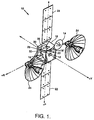
- this invention combines three distinct attitude sensors to measure the three-axis attitude of a geosynchronous satellite 10.
- Satellite 10 is a communications satellite in geosynchronous Earth orbit.
- the system and method of the present invention is particularly suitable for equatorial geosynchronous orbit applications utilizing momentum bias spacecraft, and can also accommodate inclined geosynchronous orbits.
- spacecraft in other orbits such as polar, low Earth orbit, Molniya, or the like.
- a fundamental precept of this invention involves an attitude reference which is derived from a ground-based radio-frequency (RF) beacon located at a fixed position with respect to the Earth center as viewed from the satellite.
- RF radio-frequency
- the sensors on satellite 10 include an Earth sensor 12, a space-to-ground communication link (SGL) antenna 14, and at least one sun sensor 16 mounted to the central spacecraft body 18.
- at least one additional sun sensor 16' (shown in phantom) is mounted on spacecraft body 18, to provide redundancy while also increasing the availability of a sun sensor signal.
- this embodiment provides an increased accuracy, higher bandwidth pointing reference which is available a greater percentage of the time so as to allow more frequent calibrations of the spacecraft sensors, as described in greater detail below.
- the redundancy of additional sun sensors provides a once-per-orbit sun sensor reference even if one of the sun sensors fails.
- SGL antenna 14 is mounted to body 18 of satellite 10 via a gimbal and resolver arrangement 20, as is well known in the art.
- Satellite 10 also includes one or more solar wings 22 and communication antennas 24 which are mounted to central body 18, as well as a momentum wheel 26, which is disposed within body 18.
- Momentum wheel 26 rotates about the pitch axis P in the same plane as the yaw axis Y and the roll axis R, as explained in greater detail below.
- the reference coordinate system illustrated in Figure 1 has its origin at the center of spacecraft body 18.
- Earth sensor 12 creates an attitude reference signal for measurement of the spacecraft roll and pitch attitudes with respect to the Earth center (nadir)
- the boresight of the Earth sensor is positioned along spacecraft yarn axis Y, which nominally points to the Earth nadir N E .
- the SGL antenna 14 is pointed at a target ground station S 1 and includes a companion communications package 28.
- This communications package includes an SGL autotrack sensor 30 for measuring azimuth and elevation attitude errors of SGL antenna 14 with respect to an RF beacon located at ground station S 1 .
- ground station S 1 is normally offset from Earth nadir N E such that SGL autotrack sensor 30 measures roll and pitch in a slightly different coordinate frame than that of Earth sensor 12.
- the combination of SGL autotrack sensor 30 and Earth sensor 12 provide roll, pitch, and a weakly coupled yaw measurement as explained in greater detail below.
- ground station S 1 When ground station S 1 is at the sub-satellite point, ground station S 1 appears to be collinear with Earth nadir N E as viewed from the satellite.
- the azimuth and elevation measurements of SGL autotrack sensor 30 are identical to spacecraft roll and pitch, respectively, as measured by Earth sensor 12.
- no additional attitude information is derived from SGL autotrack sensor 30 in this situation.
- SGL autotrack sensor 30 is less noisy and therefore more accurate than Earth sensor 12.
- the roll and pitch measurements obtained from SGL autotrack sensor 30 are preferred over those of Earth sensor 12.
- the spacecraft orbital location and ground station S 1 location will be selected so that ground station S 1 is offset as far as possible from Earth nadir N E .
- the maximal separation is achieved when ground station S 1 is on the horizon as viewed from satellite 10. This yields a separation angle ⁇ of about 8°.
- the separation angle ⁇ is defined as the angle between Earth nadir N E and ground station S 1 , with its vertex located at satellite 10. If the spacecraft is not in a perfect equatorial geosynchronous orbit (for example, if it is in an inclined orbit), ground station S 1 will appear to move with respect to Earth nadir N E . In this case, the predicted reference position of ground station S 1 must be known. The apparent position of ground station S 1 as measured by SGL autotrack sensor 30 must then be compared with this predicted reference position.
- a gimbal and resolver arrangement 20 is used for steering SGL antenna 14 in order to accommodate different ground stations.
- a resolver (not specifically illustrated) or other measuring device is used to measure the SGL gimbal angle with respect to satellite central body 18, as is well known in the art.
- the SGL gimbal may be driven by a stepper motor so that its angle can be tracked by counting the number of steps commanded, as is also well known in the art.
- the gimbal may be used to steer SGL antenna 14 during a daily cycle to track out the ground station's apparent motion.
- SGL antenna 14 is pointed to ground station S 1 while the Earth sensor 12 (which is fixed to spacecraft central body 18) points to Earth nadir N E .
- the position of ground station S 1 and the orbital position of the spacecraft are known prior to launch and will not substantially change, gimbal and resolver arrangement 20 may be unnecessary.
- the orientation of the SGL antenna may be fixed prior to launch.
- the spacecraft must also be in a substantially equatorial (non-inclined) geosynchronous orbit to utilize the fixed SGL antenna arrangement.
- sun sensor 16 is mounted to the spacecraft central body 18. Any of a number of commercially available precision sun sensors may be utilized. For example, the Adcole Digital Fine Sun Sensor (DFSS) manufactured by Adcole Corporation of Marlborough, Massachusetts could be used.
- DFSS Adcole Digital Fine Sun Sensor
- Sun sensor 16 provides a direct measurement of spacecraft yaw (and, incidentally, pitch) to enable accurate calibration of the SGL and Earth sensors once per orbit.
- this sensor is positioned with its boresight (the center of its field of view) collinear with spacecraft roll axis +R, but this may not be possible due to antennas or other hardware obstructing the field of view.
- sun sensor 16 may be canted "back" (i.e. away from the positive roll axis +R toward the negative yaw axis -Y), so that its boresight is typically displaced approximately 30° from positive roll axis +R.
- sun sensor 16 (and therefore its boresight) is offset from the spacecraft yaw axis toward positive roll axis +R, as illustrated in Figure 1.
- sun sensor 16 would have a square field of view of 64° by 64°, although other configurations are possible without departing from the spirit or scope of the present invention.
- a model of the ephemeris (apparent orbital motion) of the sun must be used to determine a predicted reference position of the sun assuming a perfect spacecraft attitude.
- the measured spacecraft attitude is the difference between this predicted reference position and the actual spacecraft attitude.
- this design has sufficient accuracy to meet typical relay satellite mission requirements (approximately 0.05° in roll and pitch, 0.25° in yaw).
- typical relay satellite mission requirements approximately 0.05° in roll and pitch, 0.25° in yaw.
- Earth sensor 12 and SGL autotrack sensor 30 are available to determine the spacecraft attitude.
- Each of these sensors measures two axes of attitude, in slightly different coordinate systems. In theory, the measurements from any two sensors measuring two axes each in different directions can be combined to create a measurement of all three spacecraft attitude axes.
- Earth sensor 12 is oriented toward the Earth nadir N E and measures spacecraft roll and pitch attitudes.
- SGL autotrack sensor 30 is oriented toward ground station S 1 , which is offset from Earth nadir N E by up to 8°. This separation enables the combination of measurements from SGL autotrack sensor 30 and Earth sensor 12 to measure spacecraft roll and pitch. This combined measurement is somewhat better than measurements obtained utilizing either sensor alone. This technique may also be used to provide a coarse measurement of the spacecraft yaw attitude.
- the yaw attitude measurement is very sensitive to small errors or biases in SGL autotrack sensor 30 and Earth sensor 12. Over a typical orbit, there will be incremental accumulation of these sensor biases, resulting in significant yaw pointing errors.
- Sun sensor 16 provides an accurate yaw attitude reference once per orbit which can be used to update biases of Earth sensor 12 and SGL autotrack sensor 30. This, in turn, provides an update of the yaw measurement bias when the sun is not in the field of view. Because the sun sensor measurement is available once per orbit (typically for several hours each orbit), the longest time over which it is necessary to operate utilizing only measurements from Earth sensor 12 and SGL autotrack sensor 30, is less than 24 hours. This is a significant improvement over prior art control strategies.
- SGL autotrack sensor 30 and Earth sensor 12 are used.
- two 2-axis sensors are available to determine the three-axis attitude.
- a fully optimal, general three-axis attitude determination can be computed by standard techniques. However, an approximate solution may be appropriate for small spacecraft attitude angles and a small off-nadir location of ground station S 1 .
- a processor 32 which may include hardware circuitry and software instructions, is mounted within spacecraft body 18.
- the processor 32 executes a predetermined set of instructions to compute measurements and control operation of the spacecraft.
- computations and commands may be determined by a ground station processor. Results are then relayed to the spacecraft via a communications link.
- the parameters ⁇ ES and ⁇ SGL can be selected so as to weight the measurements from SGL autotrack sensor 30 and Earth sensor 12 in a particular way depending upon the application.
- the weighting could be selected on the basis of the characteristic high-frequency random noise of the sensor.
- the weighting could depend on slowly-varying biases, depending on which term dominates the total spacecraft pointing error.
- a more sophisticated filtering scheme may be used which treats high-frequency and low-frequency sensor errors separately.
- sun sensor 16 measures the spacecraft attitude about the axes orthogonal to the line extending from the spacecraft to the sun. With sun sensor 16 oriented as illustrated in Figures 1 and 2, this provides highly accurate measurements of spacecraft pitch and yaw attitudes. Any three linearly independent measurements are sufficient to determine the spacecraft three-axis attitude. The addition of sun sensor 16 provides a total of six measurements to determine the three-axis attitude. These measurements consist of azimuth and elevation measurements provided by Earth sensor 12, sun sensor 16, and SGL autotrack sensor 30.
- three 2-axis sensors are available to determine the three-axis attitude.
- a fully optimal, general three-axis attitude determination solution can be computed by standard techniques including weighting of the different measurements for their relative errors and noises, as is known.
- a general attitude determination leads to some fairly involved calculations which may not be practical or desirable for the processor onboard the spacecraft to perform.
- Sun sensor 16 is typically a more precise device than either Earth sensor 12, or SGL autotrack sensor 30. This characteristic is utilized to develop simpler attitude measurement schemes for use in onboard control algorithms. For example, for attitude control, only the sun sensor and either SGL autotrack sensor 30 or Earth sensor 12 need to be utilized. Typically, SGL autotrack sensor 30 is better than Earth sensor 12 for this purpose. Then, the general three-axis attitude determination is solved utilizing the two selected sensors. Thereafter, this solution is also utilized to calibrate the remaining sensor.
- sun sensor 16 may be used to measure the spacecraft yaw and pitch attitudes.
- Spacecraft roll is measured by either Earth sensor 12 or SGL autotrack sensor 30.
- the general three-axis attitude determination method may be employed utilizing the two selected sensors.
- the solution may then be employed to calibrate the pitch measurements generated by Earth sensor 12 and SGL autotrack sensor 30.
- the roll measurement from the remaining sensor may also be calibrated.
- a spacecraft incorporating the control system of the present invention, uncorrupted measurements of all three spacecraft axes are available during periods when the sun is within the field of view of sun sensor 16.
- a conventional spacecraft control system may be utilized which incorporates sun sensor 16. Control performance of each axis is limited by the performance of the sensor and actuator in that axis, and the three axes can be treated as essentially decoupled control problems.
- any noise in Earth sensor 12 or SGL autotrack sensor 30 will be amplified by a factor of 1 sin ⁇ (see the "sin ⁇ " in Equation (2)) .
- This factor is at least 6.6 for a spacecraft in geosynchronous orbit. This corresponds to the maximum value of ⁇ of 8.7°. Typically, however, ⁇ would be about 8° and (1/sin ⁇ ) would be about 7.
- two ground stations located at well-separated locations on the Earth disk are utilized (see S 1 and S 2 in Figure 2) .
- two SGL antennas and corresponding SGL autotrack sensors are included on the spacecraft.
- the yarn pointing reference may be more accurate since the angle between the ground stations as viewed from the spacecraft may be up to 17.4°.
- the errors in each SGL autotrack sensor would be multiplied by at least 1/sin 17.4°, or a minimum of only 3.3 instead of the factor 6.6 achievable using the Earth sensor.
- the Earth sensor may be eliminated entirely, although at least a rudimentary Earth sensor is desirable to initially acquire Earth pointing and to provide a backup for the SGL sensors should the Earth link be lost.
- Measurements produced by Earth sensor 12 typically have significant amounts of random noise. Therefore, this scheme leads to a very noisy yaw measurement.
- the yaw control loop for the spacecraft will have a fairly low bandwidth compared to the roll and pitch control loops so that the yaw control loop is less sensitive to the noise.
- a typical yaw control time constant with this scheme might be several minutes, compared to a few seconds or tens of seconds for the roll and pitch time constants. For this reason, it is helpful to have a pitch momentum bias.
- the gyroscopic stiffness created by a sufficient pitch momentum bias will resist perturbations to yaw pointing.
- yaw attitude errors can be measured and corrected by Earth sensor 12 and SGL autotrack sensor 30.
- the yaw pointing accuracy is determined by the size of the momentum bias.
- the control strategy of the present invention provides uncorrupted attitude measurements of spacecraft roll and pitch from Earth sensor 12, and SGL autotrack sensor 30, at all times.
- the yaw axis measurement is significantly corrupted due to the noise amplification.
- the dynamics of the spacecraft pitch axis are essentially decoupled from the dynamics of the spacecraft roll and yaw axes. Therefore, a control system for pitch axis P may be designed independently from the yaw axis Y and roll axis R. Standard control system design techniques such as PID (proportional-integral-derivative) control may be utilized.
- the momentum bias does, however couple the dynamics of the roll axis R and yarn axis Y.
- the roll and yaw dynamics can therefore be considered a coupled, two-input, two-output system.
- the measurements of the control variables are directly available.
- a feedback controller may be designed for the roll/yaw dynamics using conventional techniques, such as a linear-quadratic regulator with a linear-quadratic-gaussian observer.
- the yaw axis portion of any such control system will have limited gain and bandwidth due to the significant sensor noise present in this channel.
- the simplified control system represented by the block diagram of Figure 3 provides some insight into the performance characteristics possible utilizing the present invention. The coupling of the roll and yaw dynamics is ignored since these axes are assumed to be stabilized by the coupled roll-yaw control system, as explained in detail below.
- the illustrative control system of Figure 3 is a yaw axis control system with a simplified single-axis dynamics model (coupling between roll and yaw axes is ignored).
- This block diagram illustrates some of the tradeoffs in the yaw axis control system design while demonstrating typical bandwidths achievable with this control system.
- the dynamics are represented by the yaw axis precessional dynamics.
- a yaw attitude reference signal 40 is combined with the negative feedback from the measured yaw attitude 42 and yaw sensor noise 44 at summing block 46. The result is then multiplied by a gain factor 48 to produce a commanded roll torque 50. This result is combined with a roll axis disturance torque 52 at summing block 54 before being multiplied by a simplified yaw axis dynamics model 56 (where H is the magnitude of momentum stored in the momentum wheel) to produce the actual spacecraft yarn attitude 58. If the momentum wheel spins about the negative spacecraft pitch axis, H is considered to be a positive number.
- a more complex feedback compensator such as PID might be used, but this simple model effectively illustrates the tradeoffs of the system.
- n s (s) is the effective yaw sensor noise, including the effect of amplification of SGL autotrack sensor 30 and Earth sensor 12 by: 1 sin ⁇
- Typical values for the key parameters of this system include:
- the spacecraft attitude error due to noise typically is desirable to limit the spacecraft attitude error due to noise.
- the steady-state yaw error is only 0.033 deg. This is very good performance as compared to currently available control strategies.
- geosynchronous momentum bias satellites have no direct yaw sensing capability.
- These spacecraft control both the roll and yaw axes using only a roll sensor by taking advantage of the roll-yaw coupling provided by the orbital dynamics and momentum bias.
- control systems on these spacecraft employ a yaw axis control having a time constant of two to three hours.
- the present invention provides for a time constant of only 5 minutes.
- the pointing errors of currently available satellites, due to large time-varying roll torques, would also be correspondingly larger those associated with the control system of the present invention.
- the present invention enables a yaw pointing accuracy of about 0.25°.
- a typical Earth sensor has errors which vary by about 0.02° over a day due to a variety of changes in operating conditions, such as Earth radiance changes.
- a typical SGL autotrack sensor would have diurnal errors of about 0.02° due to antenna thermal distortions, electronic offsets, and the like.
- the RSS (root-sum-square) of these error sources is about 0.03°, which, when multiplied by the factor of 7 in Equation (2), is approximately 0.21°. This term would most likely dominate the total allowable yaw error since the pointing error due to disturbance torques is limited by the feedback action described above.
- a smaller momentum bias is desirable in that it is lighter in weight and requires less power to operate. The resulting decrease in the gyroscopic stiffness of the spacecraft is accommodated by the improved control provided by the control system of the present invention.
Landscapes
- Engineering & Computer Science (AREA)
- Remote Sensing (AREA)
- Aviation & Aerospace Engineering (AREA)
- Radar, Positioning & Navigation (AREA)
- Chemical & Material Sciences (AREA)
- Combustion & Propulsion (AREA)
- Automation & Control Theory (AREA)
- Geochemistry & Mineralogy (AREA)
- Geology (AREA)
- Life Sciences & Earth Sciences (AREA)
- General Life Sciences & Earth Sciences (AREA)
- Environmental & Geological Engineering (AREA)
- Physics & Mathematics (AREA)
- Astronomy & Astrophysics (AREA)
- General Physics & Mathematics (AREA)
- Control Of Position, Course, Altitude, Or Attitude Of Moving Bodies (AREA)
- Navigation (AREA)
Claims (18)
- Engin spatial (10) ayant un système pour déterminer une mesure d'attitude trois axes de l'engin spatial (10), l'engin spatial (10) comprenantun corps d'engin spatial (18) ayant des axes de tangage (P), de roulis (R) et de lacet (Y),des moyens (12, 24, 28) pour recevoir des signaux indiquant des conditions de fonctionnement de l'engin spatial,un processeur (32) pour produire des signaux d'ordres pour commander l'engin spatial (10),un capteur terrestre (12) disposé à l'intérieur du corps d'engin spatial (18) pour créer des signaux de référence d'attitude indiquant une attitude par rapport à l'axe de roulis et une attitude par rapport à l'axe de tangage, le capteur terrestre (12) étant en communication avec le processeur (32),des moyens (14, 20, 28, 30) pour générer des signaux d'erreur indiquant une erreur d'attitude en azimut et une erreur d'attitude en site par rapport à au moins une station au sol cible (S1), les moyens de génération (14, 20, 28, 30) étant disposés à l'intérieur du corps d'engin spatial (18) et en communication avec le processeur (32),un capteur solaire (16) monté sur le corps d'engin spatial (18) et en communication avec le processeur (32), le capteur solaire (16) ayant un champ d'observation prédéterminé et fonctionnant de façon à créer des signaux de capteur solaire indiquant une attitude par rapport à l'axe de tangage et une attitude par rapport à l'axe de lacet, pendant que le soleil est à l'intérieur du champ d'observation; etdes moyens (32) pour combiner un ensemble de signaux sélectionnés dans le groupe comprenant les signaux de référence d'attitude, les signaux de capteur solaire et les signaux d'erreur, de façon à déterminer une mesure d'attitude trois axes de l'engin spatial (10).
- Engin spatial (10) selon la revendication 1, caractérisé en ce que le capteur solaire (16) est un capteur solaire numérique.
- Système selon les revendications 1 ou 2, caractérisé en ce que l'engin spatial (10) est un engin spatial soumis à l'action d'un moment cinétique, pour l'utilisation dans une application d'orbite géosynchrone, le système comprenant en outre une roue d'inertie (26) disposée à l'intérieur du corps d'engin spatial (18) pour produire une action de moment cinétique pour résister à un couple perturbateur agissant sur l'engin spatial (10), la roue d'inertie (26) pouvant tourner de l'axe de tangage (P) de l'engin spatial (10).
- Système selon l'une quelconque des revendications 1 - 3, caractérisé en ce que les moyens (14, 20, 28, 30) pour générer des signaux d'erreur comprennent :une antenne (14) montée de façon mobile sur le corps d'engin spatial (18) pour recevoir des signaux de référence provenant de la station au sol cible (S1);des moyens (20) pour pointer l'antenne (14) vers la station au sol cible (S1), les moyens de pointage (20) étant montés sur le corps d'engin spatial (18); etun capteur (28, 30) pour mesurer les erreurs d'attitude en azimut et en site par rapport à la station au sol cible (S1).
- Système selon la revendication 4, caractérisé en ce que l'engin spatial (10) est un engin spatial soumis à l'action d'un moment cinétique pour l'utilisation dans une application d'orbite géosynchrone inclinée, et en ce que les moyens (20) pour pointer l'antenne (14) manoeuvrent l'antenne (14) pendant un cycle journalier pour éliminer un mouvement apparent de la station au sol cible (S1).
- Système de la revendication 4 ou la revendication 5, caractérisé en ce que les moyens (20) pour le pointage comprennent :une monture à la Cardan fixée à l'antenne (14) et fixée au corps d'engin spatial (18) pour permettre le positionnement de l'antenne (14) par rapport au corps d'engin spatial (18);un actionneur en communication avec le processeur (32) pour positionner l'antenne (14) en réponse à un ordre de positionnement qui est produit par le processeur (32); etdes moyens pour indiquer une position réelle de l'antenne (14), les moyens d'indication étant en communication avec le processeur (32).
- Système selon la revendication 6, caractérisé en ce que les moyens d'indication comprennent un résolveur pour produire un signal représentant le mouvement de l'antenne (14).
- Système selon la revendication 6 ou la revendication 7, caractérisé en ce que l'actionneur est un moteur pas à pas et les moyens d'indication font partie intégrante du moteur pas à pas.
- Système selon l'une quelconque des revendications 1 - 8, caractérisé en outre par au moins un capteur solaire (16') supplémentaire monté sur le corps d'engin spatial (18) et en communication avec le processeur (32), chacun des capteurs solaires au nombre d'au moins un (16, 16') ayant un champ d'observation prédéterminé correspondant et fonctionnant de façon à produire des signaux de capteur solaire indiquant une attitude par rapport à l'axe de tangage et une attitude par rapport à l'axe de lacet pendant que le soleil est à l'intérieur du champ d'observation correspondant.
- Système selon l'une quelconque des revendications 1 - 9, caractérisé en ce que les moyens (14, 20, 28, 30) pour générer des signaux d'erreur génèrent des signaux indiquant une erreur d'attitude en azimut et une erreur d'attitude en site par rapport à une seconde station au sol cible (S2).
- Procédé pour déterminer une mesure d'attitude trois axes d'un engin spatial (10), l'engin spatial (10) comprenant un corps d'engin spatial (18) ayant des axes de tangage (P), de roulis (R) et de lacet (Y), des moyens (12, 24, 28) pour recevoir des signaux indiquant des conditions de fonctionnement de l'engin spatial, un processeur (32) pour générer des signaux d'ordres pour commander l'engin spatial (10), un capteur terrestre (12) monté à l'intérieur du corps d'engin spatial (18) pour créer des signaux de référence d'attitude indiquant une attitude par rapport à l'axe de roulis et une attitude par rapport à l'axe de tangage, des moyens (12, 20, 28, 30) pour produire des signaux d'erreur indiquant une erreur d'attitude en azimut et une erreur d'attitude en site par rapport à une première station au sol cible (S1), les moyens de génération (14, 20, 28, 30) étant disposés à l'intérieur du corps d'engin spatial (18), dans lequel l'engin spatial (10) comprend également un capteur solaire (16) monté sur le corps d'engin spatial (18) et en communication avec le processeur (32), le capteur solaire (16) ayant un champ d'observation prédéterminé et fonctionnant de façon à créer des signaux de capteur solaire indiquant une attitude par rapport à l'axe de tangage et une attitude par rapport à l'axe de lacet, pendant que le soleil est à l'intérieur du champ d'observation, le procédé comprenant :la détermination d'une mesure d'attitude trois axes générale, utilisant des signaux générés par deux composants sélectionnés dans le groupe comprenant le capteur terrestre (12), le capteur solaire (16), et les moyens (14, 20, 28, 30) pour générer des signaux d'erreur.
- Procédé selon la revendication 11, caractérisé en ce que la mesure d'attitude trois axes générale est utilisée pour étalonner le capteur restant non sélectionné pour déterminer la mesure d'attitude trois axes.
- Procédé selon la revendication 11 ou 12, caractérisé par la commande de l'engin spatial (10) sur la base de la mesure d'attitude trois axes.
- Procédé selon l'une quelconque des revendications 11 - 13, caractérisé en ce que la combinaison d'un ensemble de signaux comprend la détermination d'une solution approchée d'une mesure d'attitude trois axes générale.
- Procédé selon l'une quelconque des revendications 11 - 14, caractérisé en ce que la combinaison d'un ensemble de signaux comprend la détermination d'une solution approchée d'une mesure d'attitude trois axes générale donnée par les expressions :
- Procédé selon la revendication 15, caractérisé en ce que σES et σSGL sont sélectionnés de façon à pondérer les mesures provenant respectivement du capteur terrestre (12) et des moyens (14, 20, 28, 30) pour générer des signaux d'erreur.
- Procédé selon la revendication 15, caractérisé en ce que σES et σSGL sont sélectionnés sous la dépendance d'une caractéristique de bruit aléatoire de haute fréquence respectivement du capteur terrestre (12) et des moyens (14, 20, 28, 30) pour générer des signaux d'erreur.
- Procédé selon la revendication 15, caractérisé en ce que σES et σSGL sont sélectionnés sous la dépendance de biais variant lentement, respectivement du capteur terrestre (12) et des moyens (14, 20, 28, 30) pour générer des signaux d'erreur.
Applications Claiming Priority (2)
| Application Number | Priority Date | Filing Date | Title |
|---|---|---|---|
| US243669 | 1994-05-16 | ||
| US08/243,669 US5556058A (en) | 1994-05-16 | 1994-05-16 | Spacecraft attitude determination using sun sensor, earth sensor, and space-to-ground link |
Publications (2)
| Publication Number | Publication Date |
|---|---|
| EP0683098A1 EP0683098A1 (fr) | 1995-11-22 |
| EP0683098B1 true EP0683098B1 (fr) | 1999-09-15 |
Family
ID=22919638
Family Applications (1)
| Application Number | Title | Priority Date | Filing Date |
|---|---|---|---|
| EP95107371A Expired - Lifetime EP0683098B1 (fr) | 1994-05-16 | 1995-05-16 | Système de détermination de l'attitude d'un engin spatial utilisant un capteur solaire, un senseur de terre et une liaison terre-espace |
Country Status (4)
| Country | Link |
|---|---|
| US (1) | US5556058A (fr) |
| EP (1) | EP0683098B1 (fr) |
| JP (1) | JP3667817B2 (fr) |
| DE (1) | DE69512129T2 (fr) |
Cited By (1)
| Publication number | Priority date | Publication date | Assignee | Title |
|---|---|---|---|---|
| CN105539883A (zh) * | 2016-02-05 | 2016-05-04 | 上海微小卫星工程中心 | 一种基于矢量匹配的多敏感器星上自主互校验方法 |
Families Citing this family (34)
| Publication number | Priority date | Publication date | Assignee | Title |
|---|---|---|---|---|
| US5597142A (en) * | 1995-03-06 | 1997-01-28 | Space Systems/Loral, Inc. | Spacecraft acquisition of orientation by scan of earth sensor field of view |
| GB2318888A (en) * | 1996-10-30 | 1998-05-06 | Motorola Inc | Solar panel mounted sun sensor and three-axis attitude control |
| US5822515A (en) * | 1997-02-10 | 1998-10-13 | Space Systems/Loral, Inc. | Correction of uncommanded mode changes in a spacecraft subsystem |
| US6108593A (en) * | 1997-07-09 | 2000-08-22 | Hughes Electronics Corporation | Method and apparatus for estimating attitude sensor bias in a satellite |
| US6026337A (en) * | 1997-09-12 | 2000-02-15 | Lockheed Martin Corporation | Microbolometer earth sensor assembly |
| US6138953A (en) * | 1998-03-02 | 2000-10-31 | Hughes Electronics Corporation | Slew rate direction determination for acquisition maneuvers using reaction wheels |
| US6076774A (en) * | 1998-08-12 | 2000-06-20 | Hughes Electronics Corporation | Fuel and thermal optimal spiral earth acquisition |
| US6145790A (en) * | 1998-09-22 | 2000-11-14 | Hughes Electronics Corporation | Attitude determination system and method |
| EP0999128A1 (fr) * | 1998-11-06 | 2000-05-10 | Société Européenne des Satellites | Méthode pour déterminer l'angle de lacet d'un satellite |
| US6678520B1 (en) * | 1999-01-07 | 2004-01-13 | Hughes Electronics Corporation | Method and apparatus for providing wideband services using medium and low earth orbit satellites |
| US6184825B1 (en) * | 1999-06-29 | 2001-02-06 | Trw Inc. | Method and apparatus for radio frequency beam pointing |
| EP1076005B1 (fr) * | 1999-08-13 | 2007-01-03 | Hughes Electronics Corporation | Contrôle orbital d'engin spatial à retour de signal de position orbitale |
| US6311932B1 (en) * | 1999-11-30 | 2001-11-06 | Space Systems/Loral Inc. | Yaw steering momentum system |
| US6285928B1 (en) * | 2000-01-06 | 2001-09-04 | Space Systems/Loral, Inc. | Onboard attitude control using reaction wheels |
| US6550721B2 (en) * | 2000-03-09 | 2003-04-22 | The Boeing Company | Safing mode for high momentum states in body stabilized spacecraft |
| US6691033B1 (en) * | 2000-07-26 | 2004-02-10 | Hughes Electronics Corporation | System and method for calibrating inter-star-tracker misalignments in a stellar inertial attitude determination system |
| KR100400977B1 (ko) * | 2000-12-21 | 2003-10-10 | 한국항공우주연구원 | 인공위성 태양전지판의 저온환경 전개시험 장치대 |
| US6441800B1 (en) * | 2001-05-22 | 2002-08-27 | Trw Inc. | Single gimbal multiple aperture antenna |
| US6732977B1 (en) | 2002-02-11 | 2004-05-11 | Lockheed Martin Corporation | System for on-orbit correction of spacecraft payload pointing errors |
| US6695263B1 (en) | 2002-02-12 | 2004-02-24 | Lockheed Martin Corporation | System for geosynchronous spacecraft rapid earth reacquisition |
| US7051980B2 (en) * | 2002-02-26 | 2006-05-30 | Lockheed Martin Corporation | Efficient orbit sparing system for space vehicle constellations |
| US6629672B1 (en) * | 2002-03-08 | 2003-10-07 | Lockheed Martin Corporation | Sun sensor alignment compensation system |
| US6702234B1 (en) | 2002-03-29 | 2004-03-09 | Lockheed Martin Corporation | Fault tolerant attitude control system for zero momentum spacecraft |
| US7090170B1 (en) * | 2002-11-22 | 2006-08-15 | Honeywell International, Inc. | In-orbit satellite sensor alignment determination |
| US7835826B1 (en) | 2005-12-13 | 2010-11-16 | Lockheed Martin Corporation | Attitude determination system for yaw-steering spacecraft |
| US7823836B2 (en) * | 2006-12-04 | 2010-11-02 | The Boeing Company | Optimal sun safe attitude for satellite ground tracking |
| US7725259B2 (en) * | 2007-05-03 | 2010-05-25 | Raytheon Company | Trajectory estimation system for an orbiting satellite |
| US20110004405A1 (en) * | 2009-07-01 | 2011-01-06 | Optical Physics Company Inc. | Earth horizon sensor |
| US8507843B2 (en) * | 2011-05-20 | 2013-08-13 | Raytheon Company | Method and system for spectral calibration of a remote sensing sensor and a synthetic target having a tunable spectral composition |
| US8634974B2 (en) * | 2012-01-09 | 2014-01-21 | Google Inc. | Using predicted movement to maintain optical-communication lock with nearby balloon |
| US9073648B2 (en) * | 2013-02-15 | 2015-07-07 | The Boeing Company | Star tracker rate estimation with kalman filter enhancement |
| CN105424047B (zh) * | 2015-10-30 | 2018-10-30 | 上海新跃仪表厂 | 基于路标信息的航天器姿态指向误差辨识方法 |
| US10925114B1 (en) | 2019-11-11 | 2021-02-16 | Loon Llc | Remote monitoring of geographically distributed assets using mobile platforms |
| CN113485095B (zh) * | 2021-08-11 | 2022-09-13 | 中国科学院微小卫星创新研究院 | 北斗三号卫星处于地影期时预报姿态的方法 |
Family Cites Families (16)
| Publication number | Priority date | Publication date | Assignee | Title |
|---|---|---|---|---|
| US3813067A (en) * | 1972-06-29 | 1974-05-28 | Trw Inc | Attitude stabilization system |
| US4119972A (en) * | 1977-02-03 | 1978-10-10 | Nasa | Phased array antenna control |
| DE2749868C3 (de) * | 1977-11-08 | 1980-05-22 | Messerschmitt-Boelkow-Blohm Gmbh, 8000 Muenchen | Sonnen- und Erderfassungsverfahren für Satelliten |
| JPS6171300A (ja) * | 1984-09-13 | 1986-04-12 | 三菱電機株式会社 | 人工衛星の姿勢角計算装置 |
| US4725024A (en) * | 1985-11-15 | 1988-02-16 | Ford Aerospace & Communications Corporation | Method for spinning up a three-axis controlled spacecraft |
| US5139218A (en) * | 1986-07-04 | 1992-08-18 | Agence Spatiale Europeenne | Fast earth recovery procedure for earth-pointing satellites |
| DE3885883D1 (de) * | 1987-09-16 | 1994-01-05 | Deutsche Aerospace | Vorrichtung zur sollwertregelung und/oder stabilisierung von freibeweglichen körpern mit gespeichertem drall. |
| US4931942A (en) * | 1988-05-26 | 1990-06-05 | Ford Aerospace Corporation | Transition control system for spacecraft attitude control |
| US5020744A (en) * | 1990-01-12 | 1991-06-04 | General Electric Company | Method for acquiring three-axis earth pointing attitude for an initially spinning spacecraft |
| US5100084A (en) * | 1990-04-16 | 1992-03-31 | Space Systems/Loral, Inc. | Method and apparatus for inclined orbit attitude control for momentum bias spacecraft |
| US5080307A (en) * | 1990-05-14 | 1992-01-14 | Hughes Aircraft Company | Spacecraft earth-pointing attitude acquisition method |
| US5184790A (en) * | 1991-07-22 | 1993-02-09 | Hughes Aircraft Company | Two-axis attitude correction for orbit inclination |
| US5140525A (en) * | 1991-07-31 | 1992-08-18 | General Electric Company | Unified spacecraft attitude control system |
| US5257759A (en) * | 1991-11-27 | 1993-11-02 | Hughes Aircraft Company | Method and apparatus for controlling a solar wing of a satellite using a sun sensor |
| US5349532A (en) * | 1992-04-28 | 1994-09-20 | Space Systems/Loral | Spacecraft attitude control and momentum unloading using gimballed and throttled thrusters |
| US5412574A (en) * | 1993-05-14 | 1995-05-02 | Hughes Aircraft Company | Method of attitude determination using earth and star sensors |
-
1994
- 1994-05-16 US US08/243,669 patent/US5556058A/en not_active Expired - Lifetime
-
1995
- 1995-05-16 DE DE69512129T patent/DE69512129T2/de not_active Expired - Lifetime
- 1995-05-16 EP EP95107371A patent/EP0683098B1/fr not_active Expired - Lifetime
- 1995-05-16 JP JP11754395A patent/JP3667817B2/ja not_active Expired - Lifetime
Cited By (1)
| Publication number | Priority date | Publication date | Assignee | Title |
|---|---|---|---|---|
| CN105539883A (zh) * | 2016-02-05 | 2016-05-04 | 上海微小卫星工程中心 | 一种基于矢量匹配的多敏感器星上自主互校验方法 |
Also Published As
| Publication number | Publication date |
|---|---|
| EP0683098A1 (fr) | 1995-11-22 |
| JP3667817B2 (ja) | 2005-07-06 |
| DE69512129T2 (de) | 2000-05-31 |
| JPH0858699A (ja) | 1996-03-05 |
| US5556058A (en) | 1996-09-17 |
| DE69512129D1 (de) | 1999-10-21 |
Similar Documents
| Publication | Publication Date | Title |
|---|---|---|
| EP0683098B1 (fr) | Système de détermination de l'attitude d'un engin spatial utilisant un capteur solaire, un senseur de terre et une liaison terre-espace | |
| EP0769736B1 (fr) | Méthode de contrÔle de l'attitude d'un satellite stabilisé par autorotation sur une orbite inclinée | |
| US8056863B2 (en) | Unified attitude control for spacecraft transfer orbit operations | |
| US7546983B2 (en) | Spacecraft power acquisition method for wing-stowed configuration | |
| US7877173B2 (en) | Method and apparatus for determining a satellite attitude using crosslink reference signals | |
| US5257759A (en) | Method and apparatus for controlling a solar wing of a satellite using a sun sensor | |
| US6296207B1 (en) | Combined stationkeeping and momentum management | |
| US7410130B2 (en) | Star-tracker-based attitude determination for spinning spacecraft | |
| US5540405A (en) | Method and apparatus for compensating for magnetic disturbance torques on a satellite | |
| US8123173B1 (en) | Attitude and antenna steering system and method for spacecraft | |
| EP0743249B1 (fr) | Système universel de contrôle de position pour un engine spatial | |
| US6285928B1 (en) | Onboard attitude control using reaction wheels | |
| US6289268B1 (en) | Attitude determination system and method | |
| EP0792800B1 (fr) | Correction sur axe unique pour inclinaison orbitale | |
| US20100193641A1 (en) | Spacecraft Acquisition Maneuvers Using Position-Based Gyroless Control | |
| US6615117B2 (en) | Attitude determination system and method with outer-loop gyro scale-factor non-linearity calibration | |
| US7654490B2 (en) | Precision attitude control system for gimbaled thruster | |
| US20050071055A1 (en) | Refinement of spacecraft angular velocity and attitude estimates using star data | |
| US6600976B1 (en) | Gyroless control system for zero-momentum three-axis stabilized spacecraft | |
| JP2625337B2 (ja) | 日食中に人工衛星上の太陽トルク過渡現象を補償する方法および装置 | |
| US7221317B2 (en) | Space-based lever arm correction in navigational systems employing spot beams | |
| US20050133670A1 (en) | Unified sensor-based attitude determination and control for spacecraft operations | |
| EP0544241A1 (fr) | Procédé et appareil pour précompensation dynamique des mouvements pas à pas d'un panneau solaire d'un satellite | |
| Zimbelman et al. | The attitude control system design for the transition region and coronal explorer mission | |
| Adams et al. | Precision control, knowledge and orbit determination on a small spacecraft bus: The orbview-4 attitutde control system |
Legal Events
| Date | Code | Title | Description |
|---|---|---|---|
| PUAI | Public reference made under article 153(3) epc to a published international application that has entered the european phase |
Free format text: ORIGINAL CODE: 0009012 |
|
| AK | Designated contracting states |
Kind code of ref document: A1 Designated state(s): DE FR IT |
|
| 17P | Request for examination filed |
Effective date: 19960511 |
|
| 17Q | First examination report despatched |
Effective date: 19980401 |
|
| RAP1 | Party data changed (applicant data changed or rights of an application transferred) |
Owner name: HE HOLDINGS, INC. |
|
| RAP1 | Party data changed (applicant data changed or rights of an application transferred) |
Owner name: HUGHES ELECTRONICS CORPORATION |
|
| GRAG | Despatch of communication of intention to grant |
Free format text: ORIGINAL CODE: EPIDOS AGRA |
|
| GRAG | Despatch of communication of intention to grant |
Free format text: ORIGINAL CODE: EPIDOS AGRA |
|
| GRAH | Despatch of communication of intention to grant a patent |
Free format text: ORIGINAL CODE: EPIDOS IGRA |
|
| GRAH | Despatch of communication of intention to grant a patent |
Free format text: ORIGINAL CODE: EPIDOS IGRA |
|
| GRAA | (expected) grant |
Free format text: ORIGINAL CODE: 0009210 |
|
| AK | Designated contracting states |
Kind code of ref document: B1 Designated state(s): DE FR IT |
|
| REF | Corresponds to: |
Ref document number: 69512129 Country of ref document: DE Date of ref document: 19991021 |
|
| ITF | It: translation for a ep patent filed | ||
| ET | Fr: translation filed | ||
| PLBE | No opposition filed within time limit |
Free format text: ORIGINAL CODE: 0009261 |
|
| STAA | Information on the status of an ep patent application or granted ep patent |
Free format text: STATUS: NO OPPOSITION FILED WITHIN TIME LIMIT |
|
| 26N | No opposition filed | ||
| PGFP | Annual fee paid to national office [announced via postgrant information from national office to epo] |
Ref country code: FR Payment date: 20140519 Year of fee payment: 20 Ref country code: DE Payment date: 20140529 Year of fee payment: 20 Ref country code: IT Payment date: 20140526 Year of fee payment: 20 |
|
| REG | Reference to a national code |
Ref country code: DE Ref legal event code: R071 Ref document number: 69512129 Country of ref document: DE |