EP0683123A1 - Machine rotative d'impression pourvue d'un dispositif de repérage pour aligner la bande de papier - Google Patents
Machine rotative d'impression pourvue d'un dispositif de repérage pour aligner la bande de papier Download PDFInfo
- Publication number
- EP0683123A1 EP0683123A1 EP95810301A EP95810301A EP0683123A1 EP 0683123 A1 EP0683123 A1 EP 0683123A1 EP 95810301 A EP95810301 A EP 95810301A EP 95810301 A EP95810301 A EP 95810301A EP 0683123 A1 EP0683123 A1 EP 0683123A1
- Authority
- EP
- European Patent Office
- Prior art keywords
- web
- roller
- frame
- axis
- rollers
- Prior art date
- Legal status (The legal status is an assumption and is not a legal conclusion. Google has not performed a legal analysis and makes no representation as to the accuracy of the status listed.)
- Granted
Links
- 238000011144 upstream manufacturing Methods 0.000 claims abstract description 9
- 238000006073 displacement reaction Methods 0.000 claims description 6
- 230000006835 compression Effects 0.000 abstract 1
- 238000007906 compression Methods 0.000 abstract 1
- 238000012937 correction Methods 0.000 description 8
- 238000005259 measurement Methods 0.000 description 5
- 238000000034 method Methods 0.000 description 2
- 229920000049 Carbon (fiber) Polymers 0.000 description 1
- 229910000831 Steel Inorganic materials 0.000 description 1
- 230000001133 acceleration Effects 0.000 description 1
- 239000004917 carbon fiber Substances 0.000 description 1
- 239000003086 colorant Substances 0.000 description 1
- 239000002131 composite material Substances 0.000 description 1
- 230000001419 dependent effect Effects 0.000 description 1
- 238000001514 detection method Methods 0.000 description 1
- 239000002184 metal Substances 0.000 description 1
- VNWKTOKETHGBQD-UHFFFAOYSA-N methane Chemical compound C VNWKTOKETHGBQD-UHFFFAOYSA-N 0.000 description 1
- 230000003287 optical effect Effects 0.000 description 1
- 230000002093 peripheral effect Effects 0.000 description 1
- 239000010959 steel Substances 0.000 description 1
Images





Classifications
-
- B—PERFORMING OPERATIONS; TRANSPORTING
- B65—CONVEYING; PACKING; STORING; HANDLING THIN OR FILAMENTARY MATERIAL
- B65H—HANDLING THIN OR FILAMENTARY MATERIAL, e.g. SHEETS, WEBS, CABLES
- B65H23/00—Registering, tensioning, smoothing or guiding webs
- B65H23/02—Registering, tensioning, smoothing or guiding webs transversely
- B65H23/0204—Sensing transverse register of web
- B65H23/0212—Sensing transverse register of web with an element utilising fluid flow
-
- B—PERFORMING OPERATIONS; TRANSPORTING
- B41—PRINTING; LINING MACHINES; TYPEWRITERS; STAMPS
- B41F—PRINTING MACHINES OR PRESSES
- B41F13/00—Common details of rotary presses or machines
- B41F13/02—Conveying or guiding webs through presses or machines
- B41F13/025—Registering devices
-
- B—PERFORMING OPERATIONS; TRANSPORTING
- B65—CONVEYING; PACKING; STORING; HANDLING THIN OR FILAMENTARY MATERIAL
- B65H—HANDLING THIN OR FILAMENTARY MATERIAL, e.g. SHEETS, WEBS, CABLES
- B65H23/00—Registering, tensioning, smoothing or guiding webs
- B65H23/02—Registering, tensioning, smoothing or guiding webs transversely
- B65H23/032—Controlling transverse register of web
-
- B—PERFORMING OPERATIONS; TRANSPORTING
- B65—CONVEYING; PACKING; STORING; HANDLING THIN OR FILAMENTARY MATERIAL
- B65H—HANDLING THIN OR FILAMENTARY MATERIAL, e.g. SHEETS, WEBS, CABLES
- B65H23/00—Registering, tensioning, smoothing or guiding webs
- B65H23/02—Registering, tensioning, smoothing or guiding webs transversely
- B65H23/032—Controlling transverse register of web
- B65H23/038—Controlling transverse register of web by rollers
-
- B—PERFORMING OPERATIONS; TRANSPORTING
- B65—CONVEYING; PACKING; STORING; HANDLING THIN OR FILAMENTARY MATERIAL
- B65H—HANDLING THIN OR FILAMENTARY MATERIAL, e.g. SHEETS, WEBS, CABLES
- B65H2403/00—Power transmission; Driving means
- B65H2403/50—Driving mechanisms
- B65H2403/55—Tandem; twin or multiple mechanisms, i.e. performing the same operation
-
- B—PERFORMING OPERATIONS; TRANSPORTING
- B65—CONVEYING; PACKING; STORING; HANDLING THIN OR FILAMENTARY MATERIAL
- B65H—HANDLING THIN OR FILAMENTARY MATERIAL, e.g. SHEETS, WEBS, CABLES
- B65H2404/00—Parts for transporting or guiding the handled material
- B65H2404/10—Rollers
- B65H2404/15—Roller assembly, particular roller arrangement
- B65H2404/152—Arrangement of roller on a movable frame
- B65H2404/1521—Arrangement of roller on a movable frame rotating, pivoting or oscillating around an axis, e.g. parallel to the roller axis
- B65H2404/15212—Arrangement of roller on a movable frame rotating, pivoting or oscillating around an axis, e.g. parallel to the roller axis rotating, pivoting or oscillating around an axis perpendicular to the roller axis
-
- B—PERFORMING OPERATIONS; TRANSPORTING
- B65—CONVEYING; PACKING; STORING; HANDLING THIN OR FILAMENTARY MATERIAL
- B65H—HANDLING THIN OR FILAMENTARY MATERIAL, e.g. SHEETS, WEBS, CABLES
- B65H2553/00—Sensing or detecting means
- B65H2553/10—Sensing or detecting means using fluids, e.g. pneumatics
Definitions
- the invention relates to a rotary web printing machine with two cylinders forming the printing nip, between which the paper web passes under pressure on at least one side, and with a register device for aligning the web, this device having inlet and outlet rollers which guide the web and whose position can be controlled by measuring signals from web edge sensors by means of an adjusting device.
- EP-A-0 415 881 describes a web printing machine with a plurality of printing units, in which the paper web is driven and guided by means of drawing rollers which are installed on both sides of the printing nip of each printing unit.
- a paper web store and a register device arranged in front of it for lateral alignment of the paper web are installed in front of the pull rollers, which lie in front of the printing nip of each printing unit, and a paper web store is arranged downstream of the pull rollers behind each printing nip.
- the devices for laterally aligning the paper web have a rotating frame on which the paper web is guided by inlet and outlet rollers mounted on the frame ends and the position of which can be controlled by measurement signals from web edge sensors for the purpose of correcting the position of the paper web.
- the arrangement of these devices in the known web printing machine according to EP-A-0 415 881 requires a considerable amount of space in the transport system of the paper web before it passes through the first paper web store. In addition, any deviations from the correct one that occur when passing through the paper web store and the drawing roller can occur Paper web position can no longer be compensated.
- the printing units are designed in the manner of sheet-fed printing units, in which the cylinders forming the printing nip have printing zones separated by cylinder pits.
- the known web printing machine is set up for a so-called crawl step operation. This means that the paper web is only transported at a constant speed in front of and behind each printing unit and during a printing process, when it is in contact with the printing zones of both cylinders, whereas when it passes through a cylinder pit, i.e.
- the paper web runs synchronously with the cylinders again as it passes the following printing zone.
- print images of variable length can be generated, individual register corrections made for each individual print and the repeat length of the individual prints on the paper web independent of the Length of the printed images can be varied.
- the paper web Because of the very high dynamics with which the paper web has to be pulled back and accelerated again, they are designed as vacuum accumulators which do not have to be accelerated Guide rollers made of metal, but do not guarantee lateral guidance of the web. For certain paper qualities, if the paper is not homogeneous across the web width, a lateral pendulum movement of the web can occur, which is not permitted for the required page register, especially for banknote printing. In addition, due to an inhomogeneity, the paper web can tend to run obliquely through the printing unit, which would result in correspondingly oblique prints on the web.
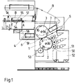
- FIG. 1 schematically shows a web printing machine, in which the paper web B runs through an intaglio printing unit, which is designed in the manner of a sheet-fed printing unit with a plate cylinder 2 and with a printing cylinder 3.
- These two cylinders 2 and 3 mounted in the machine frame 1 form the pressure gap S through which the paper web B passes and have pressure saddles 2a and 3a separated by cylinder pits 2b and 3b, respectively, which form the printing zones and, in the case of the plate cylinder 2, the intaglio printing plates, in the case of the printing cylinder, wear the printing covers.
- these cylinders each have three pressure zones.
- the clamping elements for the pressure plates or the pressure covers are accommodated in the cylinder pits 2b and 3b.
- Pull rollers 4 and 5 are installed in front of and behind the pressure gap S, which should be as close as possible to the pressure gap and which are controlled in such a way that the web section between these pull rollers is transported in the aforementioned vocational step.
- these pull rollers 4, 5 and the cylinders 2, 3 rotate at the same peripheral speed.
- the pull rollers 4 and 5 are known suction rollers, which hold the section of the paper web that wraps around them by negative pressure, so that no pressure rollers are required.
- a paper web store 6 or 7 in the form of a known vacuum store is installed in front of the draw roller 4 and behind the draw roller 5.
- the plate cylinder 2 is colored by three stencil rollers 50 with different colors, which in turn are colored by inking units 51 which are installed on a removable inking unit frame 52.
- the directions of rotation of the cylinders and the direction of transport of the paper web B are indicated by arrows.
- a wiping device 53 acting on the plate cylinder is installed behind the stencil rollers.
- a register device 54 arranged in the transport direction in front of the paper web storage 6 with a rotating frame 55, which has two spaced guide rollers 56 and 57 for the paper web B and the position of which is controlled by web edge buttons, not shown.
- This device 54 requires a sufficiently long inlet section E, which must be at right angles to the rotating frame 55, and an adequate one long outlet section A; in addition, at least one further guide roller 58 is required at the end of the outlet section A, which changes the direction of the paper web by at least 90 °.
- the device 54 or a similar device would have to be installed between the first drawing roller 4 and the printing nip S, but this is not practically possible.
- the web section between the pull roller 4 and the pressure nip S would be inadmissibly long, and on the other hand, the guide rollers could not be accelerated without slippage during the very dynamic acceleration processes in the crawlage step by the paper web, with the result that the lateral guidance of the web would be lost.
- the present invention is based on the object of designing and arranging a register device for aligning the paper web in web-fed printing machines in a space-saving manner in such a way that an exact alignment of the paper web is ensured when passing through the printing nip, wherein any possible skewing of the web can also be corrected without an impermissibly long path section must be available for this register device before the printing nip.
- These can be conventional web printing machines with constant paper web transport, which do not require a paper web storage; in particular, however, the register device according to the invention should be applicable to web-fed printing presses operating in the vocational step mode and should avoid the specific difficulties mentioned which arise with these printing presses.
- the space immediately available on both sides of the printing nip is used to accommodate the guiding device, which allows the position of the paper web in the printing nip to be corrected directly.
- the guide device can be designed as a rotating frame, the inlet roller and outlet roller of which are located on both sides of the printing nip.
- the arrangement is preferably such that the two pulling rollers act as adjustable inlet and outlet rollers on both sides of the printing nip.
- the first embodiment of the invention shown in Figures 2 and 3 relates to a conventional web printing press with constant paper web transport and the two printing unit cylinders 2 and 3 forming the printing nip S, and with a register device which consists of a guide device for the paper web B in the form of a rotating frame 10 and consists of a feed device upstream of this rotating frame, also in the form of a rotating frame 20.
- the rotating frame 10 has a rectangular frame 11, which in the example according to FIG. 2 is movably mounted above the printing couple cylinders 2 and 3 on the machine frame 1 and on the inlet side there is an inlet roller 14 in front of the printing nip S and on the outlet side an outlet roller behind the printing nip S. 15 has.
- rollers 14 and 15 are mounted on the ends of support rods 12 and 13 which are attached to the underside of the frame 11 and extend to the height of the pressure gap S, which is located centrally between the rollers 14 and 15.
- the width of the rotating frame 10 is greater than the length of the cylinders 2, 3.
- the rotating frame 20 also has a rectangular frame frame 21 with an inlet roller 22 and an outlet roller 23 and is rotatably mounted about an axis 24 which is fixedly mounted in the machine frame 1 and which is arranged centrally to the inlet roller 22 and in a perpendicular to the axis of this inlet roller 22 and thus also to the axis of the inlet roller 14 oriented plane.
- the plane of the rotating frame 20 is offset parallel to the plane of the rotating frame 10.
- the outlet side of the rotating frame 20 and the inlet side of the rotating frame 10 lie at least approximately vertically one above the other and are connected to one another by a free axis 25 which is arranged centrally to the rollers 14 and 23.
- This axis forms a common pivot axis 25 for both rotating frames that is displaceable relative to the machine frame 1 and is perpendicular to the plane passing through the axis of the rollers 14 and 15.
- the paper web B runs in the direction of the arrows over a guide roller 26 to the inlet roller 22 of the rotating frame 20, then over the outlet roller 23 of this rotating frame, which deflects the paper web by 90 ° in the direction of the inlet roller 14 of the rotating frame 10, where it is redirected by 90 °.
- the paper web B passes the printing nip S and is then transported further via a further guide roller 27.
- web edge sensors 16 and 17 are provided, which in the example under consideration are arranged close to the inlet roller 14 or close to the outlet roller 15, along the web sections running perpendicular to the plane of the rotating frame 10 and check the lateral alignment or a possible skew of the web.
- These web edge sensors are known, non-contact sensors, in particular optical or pneumatic sensors.
- the measurement signals of these web edge sensors 16 and 17 control two actuators 18 and 19.
- the first actuator 18 can pivot axis 25, that is to say the rollers 14 and 23 connected thereto, transversely to the direction of travel of paper web B and the second actuator 19, independently of actuator 18 , Adjust the outlet side 15 of the rotating frame 10 with the outlet roller 15 also transversely to the web running direction in one direction or the other.
- the actuators 18 and 19 are connected in an articulated manner to the frame parts carrying the relevant rollers in such a way that these rollers can be adjusted in the direction of their axes, possibly with simultaneous pivoting, that is to say they can be displaced in a plane passing through the roller axes.
- This individual adjustment of the rollers mentioned as a function of the measurement signals of the web edge sensors 16 and 17 allows both pure side corrections by a parallel displacement of the paper web and corrections of skewing Make paper web, as illustrated below with reference to Figures 4 to 6.
- a lateral correction of the paper web B takes place in that both actuators 18 and 19 are shifted in the same direction by the same amount that the paper web again runs centrally between the two web edge sensors 16 and 17.
- the rotating frame 10 and thus the web section passing through the printing nip between the inlet roller 14 and the outlet roller 15 are displaced in the direction of the straight arrow perpendicular to the web running direction, while the rotating frame 20 about the stationary axis 24 in the sense of the curved arrow, and accordingly the common free pivot axis 25 is pivoted.
- the web edge sensors 16 and 17 have reported different deviations of the web from the central course, so that an oblique correction is necessary.
- the two actuators 18 and 19 adjust the rollers assigned to them by the same amount in the opposite direction. Since the pressure gap S lies centrally between the inlet and outlet rollers 14 and 15 of the rotating frame 10, this has the consequence that the rotating frame 10 performs a certain rotation in the sense of the curved arrow about the fictitious axis of rotation D, which passes through the printing gap S in the middle and lies on the connecting line between the axes of both cylinders 2 and 3, while the rotating frame 20 is rotated about the fixed axis of rotation 24 in the opposite direction. In this way, a pure angular correction of the paper web about the fictitious axis of rotation D takes place without lateral displacement. In the example according to FIG. 4, this fictitious axis of rotation D was only on the side postponed.
- a combined correction takes place, namely a lateral displacement and a simultaneous rotation of the paper web.
- the outlet roller 23 of the rotating frame 20 and the inlet roller 14 of the rotating frame 10 are adjusted in one direction by a greater amount by corresponding adjustment of the common axis 25 by means of the actuator 18 than the outlet roller 15 of the rotating frame 10 by means of the other actuator 19 in the other direction.
- Both rotating frames are thus rotated in different directions in the sense of the curved arrows, and at the same time the rotating frame 10 is displaced in the sense of the straight arrow.
- the web web can be correctly aligned with the printing unit cylinders by means of adjustable web edge buttons before the start of printing, by mechanically or electrically adjusting the position of these web edge buttons.
- FIG. 7 shows the same printing machine as FIG. 1 with a plate cylinder 2 inked by stencil rollers 50 and a printing cylinder 3, both cylinders having three printing zones 2a and 3a separated by cylinder pits 2b and 3b.
- a pulling roller 4 and an upstream paper web storage 6 are installed in front of the printing nip, a pulling roller 5 and a downstream paper web storage 7 are installed behind the printing nip.
- the draw rollers are controlled suction rollers on which the paper web passes Negative pressure is maintained.
- the difference from the printing machine according to FIG. 1 is the arrangement and design of the register device, the function of which is taken over by the pull rollers 4, 5 and the paper web storage 6.
- the pull roller 4 in front of the pressure nip S forms the inlet roller and the pull roller 5 behind the pressure nip S the outlet roller of a guide device which corresponds to the rotating frame 10 according to FIGS. 2 to 6.
- Both pulling rollers 4 and 5 are mounted in a common frame which consists of a frame part 30 for the pulling roller 4, a frame part 31 for the pulling roller 5 and a connecting frame 32 which is fastened to the frame parts 30 and 31 by means of point fastenings.
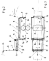
- the width of the frame is so much greater than the length of the printing couple cylinders 2 and 3 that these cylinders lie within the frame in the plan view according to FIG. 10.
- the connecting frame 32 which is preferably a light frame made of steel tube or carbon fiber composite material, absorbs the paper tensile forces and the transverse forces between the pull rollers.
- the frame with the pull rollers 4 and 5 is movably mounted in a plane going through the axes of the pull rollers 4 and 5.
- the frame parts 30 and 31 are provided on both sides with angle pieces 35, 36 and 37, 38, the legs of which are oriented parallel to the axis of the drawing rollers and all lie in one plane and are movably supported on both sides in the machine frame 1 by means of ball guides 39.
- the axis of the guide device corresponding to the free pivot axis 25 in the example according to FIGS. 2 to 6 is formed by a cam roller 40, which is supported according to FIGS Axis is oriented perpendicular to the plane passing through the axes of the drawing rollers.
- This cam roller 40 is guided in a groove 41 which runs parallel to the axis of the pull roller 4 and is provided in a guide segment 65 fastened to the machine frame 1. With this guidance, the free pivot axis of the frame 30, 31, 32 formed by the cam roller 40 can only be moved parallel to the pull roller axis.
- an individual, articulated actuator 42 or 43 engages, which can adjust each end of the frame, that is, each of the two pull rollers 4 and 5, in the axial direction thereof, depending on the measurement signals in front and behind the web nip switches 16 and 17 installed in the printing nip, which here lie directly behind the first pull roller 4 and in front of the second pull roller 5, respectively.
- the whole arrangement is such that the pressure gap S is in the middle between the two adjustable pull rollers 4 and 5 and the entire frame with the pull rollers 4 and 5 makes a fictitious rotation around one in the pressure gap S on the connecting line of the axes of plate cylinders 2 and pressure cylinder 3 lying pivot point D, when the two pull rollers 4 and 5 are adjusted by their actuators 42 and 43 by different amounts, corresponding to the positions of the rotating frame 10 according to Figures 5 and 6.
- both pull rollers 4 and 5 by their actuators 42 and 43 are adjusted by the same amount in the same direction, then one is found Pure parallel displacement of the frame and thus of the paper web section between the rollers 4 and 5 takes place, corresponding to the representation of the rotating frame 10 according to FIG. 4.
- the feed device 20 appearing in FIGS. 2 to 6 is formed in the example according to FIGS. 7 to 11 by the paper web storage 6, which is mounted on the machine frame 1 on its inlet side about a stationary axis 46 running along the incoming section of the paper web B.
- this tilting axis 46 lies in a plane oriented perpendicular to the axis of the inlet roller of the guide device, that is to say to the axis of the pull roller 4, which intersects this axis at least approximately in the middle.
- the paper web storage 6 and the frame part 30, in which the pull roller 4 is mounted, are mechanically connected to one another by a hinged tie rod 47.
- This tie rod 47 is articulated on the side opposite the tilt axis 46 of the paper web storage 6, on which the paper web runs out; the other end of the tie rod 47 is articulated on the left side of the frame part 30 of the drawing roller 4 according to FIG.
- the pivot axis 25 has the function of the mechanical connection between the feeding and guiding device.
- the paper web B passes through an inlet roller 48 into the paper web store 6, which is a vacuum store.
- the outlet roller of this paper web store is identical to the pull roller 4, that is to say the inlet roller of the guide device.
- the arrangement described ensures that when the frame part 30 is adjusted with the pull roller 4, the paper web storage 6 is moved by the tie rod 47 with a corresponding rotation about the Tilt axis 46 is taken along in such a way that the direction of the paper web entering the guide device via the pull roller 4 is changed accordingly, as is shown in principle by FIGS. 4 to 6 for the embodiment with two coupled rotating frames.
- the drawing rollers 4 and 5 and the paper web storage 6 form the guiding and feeding devices directly, any additional mass of the devices to be accelerated, for example for additional paper guiding rollers, is avoided, and the paper web section in the area of the printing nip S between the pull rollers 4 and 5 is not additionally extended.
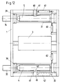
- the exemplary embodiment according to FIG. 12 shows a guide device in which the inlet and outlet rollers are also formed by pull rollers 4 and 5, which are mounted on both sides of the printing nip of a printing unit operating in the vocational step mode in frame parts 30 and 31, of which the frame part 30 is precise is designed and guided as in the example according to FIGS. 2 to 6.
- Both frame parts 30, 31 are in turn displaceably mounted in frame 1 by means of ball guides 39 in the plane passing through the drawing roller axes.
- these frame parts 30 and 31 are independent of one another and are not connected to one another by a connecting frame.
- the frame roller 31 carrying the pull roller 5 is also provided, like the frame 30, in the middle with a cam roller 60 which is guided in a groove 61 in the machine frame 1 which runs parallel to the axis of the pull roller and whose axis is perpendicular to that through the Roll axis going plane stands.
- each frame part 30 and 31 is subject to the action of a second actuator 62. 63, which can perform a displacement perpendicular to the pull roller axis and thus for the exact angular position of the pull rollers 4. 5, again as a function of the measurement signals of the web edge finder.
- the pull rollers are then aligned together in such a way that they assume exactly the position that they would assume using a mechanical connecting frame.
- the two pull rollers 4 and 5 then belong, so to speak, to an "electronic rotating frame".
- the actuators must either be equipped with stepper motors or have suitable sensors for position detection.
- the embodiment without a connecting frame between the drawing rollers is always advantageous when there is not enough space in the printing unit.
- FIGS. 13 and 14 show a further embodiment of a guide device in which the pull rollers 4 and 5 form the inlet and outlet rollers on both sides of the pressure nip and, as in the example according to FIG. 12, are mounted in mutually independent frame parts 30 and 31 which are supported by means of ball guides 39 are in turn displaceable in the plane passing through the roller axes.
- the frame part 30 with the pull roller 4 is, as in the example according to FIGS. 11 and 12, guided in the frame 1 by means of a centrally located cam roller 40, which is adjustable in a groove 41 parallel to the axis of the cylinder 3 of a guide segment 65 fastened in the frame 1 .
- the other frame part 31 is guided by two cam rollers 66 and 67 in the machine frame 1, the two cam rollers being arranged as far as possible outside the center of the pull roller 5 between the paper web edge and the inner edge of the machine frame.
- These cam rollers the axes of which in turn are perpendicular to the plane passing through the roller axes, run in grooves 70 and 71 of guide segments 68 and 69, which can be adjusted individually inclined to the axis of rotation of the pulling rollers in such a way that for the frame part 31 with the pulling roller 5 fictional pivot point is generated, which coincides with the pivot point of the cam roller 40.
- This is illustrated in FIG. 13 by the two dash-dotted lines which start from the cam rollers 66 and 67 and intersect at the pivot point of the cam roller 40.
- Both frame parts 30 and 31 are connected to one another by a push rod 74 which, outside of the machine frame 1, connects the motors 72 and 73 which are fixedly flanged to the frame parts 30 and 31.
- each pull roller 4 and 5 only requires one actuator 42 and 43. Due to the arrangement of the guides in the grooves 41, 70 and 71, the pull roller 4 can be guided through the groove 41, moved parallel to cylinder 3. The degree of freedom of rotation about the axis of cam roller 40 then remains. This rotation is controlled by the push rod 74 mentioned.
- the pulling roller 5 is displaced in the guide grooves 70 and 71, it approximately describes an arc around the cam roller 40.
- the push rod 74 also rotates the pulling roller 4 around the cam roller 40 and always keeps it at least approximately parallel to the pulling roller 5.
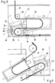
- FIGS. 14 and 15 show a further embodiment of the upstream feed device in the form of a rotating frame 75, which has the inlet roller 78 and the outlet roller 79 and is mounted in the center 1 on its input side with the axis of rotation 77 in the frame 1 and by means of an articulated push rod 76 the frame part 30 of the pull roller 4 is connected.
- the paper storage 6 is thus firmly anchored in the machine frame 1 and lies within the transport path of the paper web between the rotating frame 75 forming the feed device and the web guiding device, which is essentially formed by the two frame parts 30 and 31.
- This arrangement results in a greater correction length K (FIG. 15) than is possible by using the web store 6 as a feed device in the example according to FIGS. 7 to 11.
- the upstream rotating frame 75 essentially corresponds to the rotating frame 20 in the example according to FIGS. 2 to 6, the inlet and outlet rollers 78, 79 corresponding to the inlet and outlet rollers 22 and 23 and the axis of rotation 77 of the axis of rotation 24.
- the register device shown in FIGS. 2 to 6 can be provided with two rotating frames, while in web printing machines with paper web transport operating in stair step mode, the two pulling rollers and the first paper web storage device or the upstream turning frame form the guide and feed device .
- the device according to the invention allows a paper web which, due to inhomogeneity in the paper, runs obliquely out of the paper web store over the web width or reaches the feed roller of the guide device at an angle, or oscillating their direction changes, by appropriate control and deflection of the inlet and outlet rollers to align exactly to the printing nip, so that an exact side register and inclined register are maintained.
- the drawing rollers can also be ordinary drawing rollers which cooperate with a pressure roller, that is to say part of a customary drawing roller group, and the paper web stores can be of any type.
Landscapes
- Engineering & Computer Science (AREA)
- Mechanical Engineering (AREA)
- Physics & Mathematics (AREA)
- Fluid Mechanics (AREA)
- Inking, Control Or Cleaning Of Printing Machines (AREA)
- Rotary Presses (AREA)
- Replacement Of Web Rolls (AREA)
Applications Claiming Priority (2)
| Application Number | Priority Date | Filing Date | Title |
|---|---|---|---|
| CH1579/94 | 1994-05-20 | ||
| CH01579/94A CH688137A5 (de) | 1994-05-20 | 1994-05-20 | Rotations-Rollendruckmaschine mit einer Registervorrichtung zum Ausrichten der Papierbahn. |
Publications (2)
| Publication Number | Publication Date |
|---|---|
| EP0683123A1 true EP0683123A1 (fr) | 1995-11-22 |
| EP0683123B1 EP0683123B1 (fr) | 1998-10-28 |
Family
ID=4213726
Family Applications (1)
| Application Number | Title | Priority Date | Filing Date |
|---|---|---|---|
| EP95810301A Expired - Lifetime EP0683123B1 (fr) | 1994-05-20 | 1995-05-04 | Machine rotative d'impression pourvue d'un dispositif de repérage pour aligner la bande de papier |
Country Status (8)
| Country | Link |
|---|---|
| US (1) | US5540146A (fr) |
| EP (1) | EP0683123B1 (fr) |
| CN (1) | CN1081538C (fr) |
| CA (1) | CA2148986C (fr) |
| CH (1) | CH688137A5 (fr) |
| DE (1) | DE59504031D1 (fr) |
| DK (1) | DK0683123T3 (fr) |
| RU (1) | RU2129489C1 (fr) |
Cited By (6)
| Publication number | Priority date | Publication date | Assignee | Title |
|---|---|---|---|---|
| EP0860274A1 (fr) * | 1996-11-27 | 1998-08-26 | Société d'Etude de Machines pour les Arts Graphiques | Dispositif de mise en ligne d'une bande utilisée dans une machine rotative d'impression |
| EP1080887A1 (fr) * | 1999-08-19 | 2001-03-07 | Quad/Tech, Inc. | Système de contrôle de la position d'une bande |
| EP1842665A1 (fr) | 2006-04-04 | 2007-10-10 | Kba-Giori S.A. | Procédé de production de papiers de sécurité, machine d'impression héliogravure pour réaliser ledit procédé et papier de sécurité produit selon ledit procédé |
| EP2119527A1 (fr) | 2008-05-16 | 2009-11-18 | Kba-Giori S.A. | Procédé et système pour la fabrication de plaques d'impression en creux pour la production de papiers sécurisés |
| WO2009083149A3 (fr) * | 2007-12-27 | 2009-11-19 | Giesecke & Devrient Gmbh | Transfert de structures à imprimer et/ou à reproduire par estampage sur une feuille sans fin |
| DE102013218890A1 (de) * | 2013-09-20 | 2015-03-26 | Koenig & Bauer Aktiengesellschaft | Verfahren und Vorrichtung zum Breitstrecken und/oder seitlichen Versetzen einer Bahn sowie Breitstreckvorrichtung im Bahnweg einer Druckmaschine |
Families Citing this family (18)
| Publication number | Priority date | Publication date | Assignee | Title |
|---|---|---|---|---|
| US5813337A (en) * | 1996-06-05 | 1998-09-29 | Quad/Tech, Inc. | Closed-loop printing control system |
| US6038977A (en) * | 1998-06-19 | 2000-03-21 | Haney; Daniel E. | Multiple printing process registration method |
| US6244183B1 (en) | 1998-06-19 | 2001-06-12 | Haney Graphics | Multiple printing process pin registration method and apparatus |
| US6164201A (en) * | 1998-09-11 | 2000-12-26 | Heidelberger Druckmachinen Ag | Method and apparatus for web steering |
| DE19913855A1 (de) * | 1999-03-26 | 2000-09-28 | Focke & Co | Verfahren und Vorrichtung zum Bedrucken von Zuschnitten |
| JP2007229954A (ja) * | 2006-02-27 | 2007-09-13 | Mitsubishi Heavy Ind Ltd | 印刷機械のニップ確認システム、およびプログラム |
| DE102007034246B4 (de) * | 2007-07-23 | 2010-10-28 | OCé PRINTING SYSTEMS GMBH | Einrichtung mit einer Vorzentriervorrichtung und einer Puffervorrichtung für die Zufuhr einer Bedruckstoffbahn zu einer Druckeinrichtung |
| DE102009047776B4 (de) * | 2009-09-30 | 2012-04-26 | Eastman Kodak Co. | Verfahren und Vorrichtung zum Messen einer Laufrichtung einer Substratbahn |
| US9463942B2 (en) * | 2013-09-24 | 2016-10-11 | The Procter & Gamble Company | Apparatus for positioning an advancing web |
| US9931664B2 (en) * | 2013-10-18 | 2018-04-03 | The Chinese University Of Hong Kong | Roll-to-roll printing systems and methods for fabricating print roller |
| CN105922743B (zh) * | 2016-04-21 | 2017-10-24 | 南京富士通电子信息科技股份有限公司 | 证件打印机中采用纸幅检测传感器实现首行定位的方法 |
| CN105858305A (zh) * | 2016-06-12 | 2016-08-17 | 镇江金山物流中心 | 一种收卷压轮机构 |
| CN106890796B (zh) * | 2017-03-30 | 2023-04-14 | 福莱特玻璃集团股份有限公司 | 一种玻璃钢化后全自动流水线 |
| WO2020091731A1 (fr) * | 2018-10-29 | 2020-05-07 | Hewlett-Packard Development Company, L.P. | Compensation de décalage de bande |
| WO2020171826A1 (fr) * | 2019-02-22 | 2020-08-27 | Hewlett-Packard Development Company, L.P. | Appareil et procédés d'impression offset |
| CN112549746B (zh) * | 2020-12-02 | 2022-05-24 | 浙江聚众柔印科技有限公司 | 一种液态柔性树脂印刷卷筒 |
| IT202100012509A1 (it) * | 2021-05-14 | 2022-11-14 | Fabio Moneta | Dispositivo a ballerino per lavorazioni su film a scorrimento continuo. |
| CN116653411B (zh) * | 2023-07-20 | 2023-09-29 | 苏州同里印刷科技股份有限公司 | 一种用于印刷工艺的纸张纠偏装置及纠偏方法 |
Citations (5)
| Publication number | Priority date | Publication date | Assignee | Title |
|---|---|---|---|---|
| EP0018223A1 (fr) * | 1979-04-19 | 1980-10-29 | Baldwin Technology Corporation | Système de guidage de matériau en bande |
| DE3913700C1 (en) * | 1989-04-26 | 1990-11-15 | Erhardt + Leimer Gmbh, 8900 Augsburg, De | Tracking system for moving strip - uses two rollers on common support with self-aligning bearings on vertical pivots |
| EP0415881A2 (fr) * | 1989-08-30 | 1991-03-06 | De La Rue Giori S.A. | Machine rotative d'impression combinée, particulièrement pour imprimer les papiers de valeur |
| DE8304988U1 (de) * | 1983-02-23 | 1991-11-07 | Klemm, Gerhard, Ing.(grad.), 4800 Bielefeld | Mit Gegendruckwalze arbeitende Druckmaschine, vorzugsweise Siebdruckmaschine |
| EP0562159A1 (fr) * | 1992-03-23 | 1993-09-29 | OFFICINE MECCANICHE GIOVANNI CERUTTI S.p.A. | Dispositif de mise en registre dans le sens longitudinal et transversal d'une bande de papier dans une machine à imprimer rotative |
Family Cites Families (5)
| Publication number | Priority date | Publication date | Assignee | Title |
|---|---|---|---|---|
| FR2354878A2 (fr) * | 1976-06-18 | 1978-01-13 | Chambon Machines | Dispositif de reperage des couleurs pour impression sur materiaux legers |
| IT1087472B (it) * | 1977-11-07 | 1985-06-04 | Reggiani Spa | Apparecchatura da stampa a cilindri rotanti per stampare specularmente disegni e/o colori uguali sulle opposte facce di un tessuto o simile |
| JPH0729413B2 (ja) * | 1988-08-31 | 1995-04-05 | 株式会社東京機械製作所 | 輪転機における通紙経路正誤確認装置 |
| US4889211A (en) * | 1988-09-14 | 1989-12-26 | Carlson Sterling R | Printing press idle roller braking system |
| DE4039108C1 (fr) * | 1990-12-07 | 1992-04-16 | Man Roland Druckmaschinen Ag, 6050 Offenbach, De |
-
1994
- 1994-05-20 CH CH01579/94A patent/CH688137A5/de not_active IP Right Cessation
-
1995
- 1995-05-03 US US08/434,275 patent/US5540146A/en not_active Expired - Lifetime
- 1995-05-04 EP EP95810301A patent/EP0683123B1/fr not_active Expired - Lifetime
- 1995-05-04 DK DK95810301T patent/DK0683123T3/da active
- 1995-05-04 DE DE59504031T patent/DE59504031D1/de not_active Expired - Fee Related
- 1995-05-09 CA CA002148986A patent/CA2148986C/fr not_active Expired - Fee Related
- 1995-05-18 RU RU95107886A patent/RU2129489C1/ru active
- 1995-05-19 CN CN95106204A patent/CN1081538C/zh not_active Expired - Fee Related
Patent Citations (5)
| Publication number | Priority date | Publication date | Assignee | Title |
|---|---|---|---|---|
| EP0018223A1 (fr) * | 1979-04-19 | 1980-10-29 | Baldwin Technology Corporation | Système de guidage de matériau en bande |
| DE8304988U1 (de) * | 1983-02-23 | 1991-11-07 | Klemm, Gerhard, Ing.(grad.), 4800 Bielefeld | Mit Gegendruckwalze arbeitende Druckmaschine, vorzugsweise Siebdruckmaschine |
| DE3913700C1 (en) * | 1989-04-26 | 1990-11-15 | Erhardt + Leimer Gmbh, 8900 Augsburg, De | Tracking system for moving strip - uses two rollers on common support with self-aligning bearings on vertical pivots |
| EP0415881A2 (fr) * | 1989-08-30 | 1991-03-06 | De La Rue Giori S.A. | Machine rotative d'impression combinée, particulièrement pour imprimer les papiers de valeur |
| EP0562159A1 (fr) * | 1992-03-23 | 1993-09-29 | OFFICINE MECCANICHE GIOVANNI CERUTTI S.p.A. | Dispositif de mise en registre dans le sens longitudinal et transversal d'une bande de papier dans une machine à imprimer rotative |
Cited By (10)
| Publication number | Priority date | Publication date | Assignee | Title |
|---|---|---|---|---|
| EP0860274A1 (fr) * | 1996-11-27 | 1998-08-26 | Société d'Etude de Machines pour les Arts Graphiques | Dispositif de mise en ligne d'une bande utilisée dans une machine rotative d'impression |
| EP1080887A1 (fr) * | 1999-08-19 | 2001-03-07 | Quad/Tech, Inc. | Système de contrôle de la position d'une bande |
| EP1842665A1 (fr) | 2006-04-04 | 2007-10-10 | Kba-Giori S.A. | Procédé de production de papiers de sécurité, machine d'impression héliogravure pour réaliser ledit procédé et papier de sécurité produit selon ledit procédé |
| EP2065187A1 (fr) | 2006-04-04 | 2009-06-03 | Kba-Giori S.A. | Procédé de production de papiers de sécurité, machine d'héliogravure pour réaliser ce procédé, et papier de sécurité produit par ce procédé |
| WO2009083149A3 (fr) * | 2007-12-27 | 2009-11-19 | Giesecke & Devrient Gmbh | Transfert de structures à imprimer et/ou à reproduire par estampage sur une feuille sans fin |
| EP2119527A1 (fr) | 2008-05-16 | 2009-11-18 | Kba-Giori S.A. | Procédé et système pour la fabrication de plaques d'impression en creux pour la production de papiers sécurisés |
| EP2743025A2 (fr) | 2008-05-16 | 2014-06-18 | KBA-NotaSys SA | Procédé et système pour la fabrication de plaques d'impression en creux dans la production de papiers sécurisés |
| US9796202B2 (en) | 2008-05-16 | 2017-10-24 | Kba-Notasys Sa | Method and system for manufacturing intaglio printing plates for the production of security papers |
| DE102013218890A1 (de) * | 2013-09-20 | 2015-03-26 | Koenig & Bauer Aktiengesellschaft | Verfahren und Vorrichtung zum Breitstrecken und/oder seitlichen Versetzen einer Bahn sowie Breitstreckvorrichtung im Bahnweg einer Druckmaschine |
| DE102013218890B4 (de) * | 2013-09-20 | 2019-11-07 | Koenig & Bauer Ag | Druckmaschine mit einer Breitstreckvorrichtung |
Also Published As
| Publication number | Publication date |
|---|---|
| CN1118306A (zh) | 1996-03-13 |
| RU2129489C1 (ru) | 1999-04-27 |
| CN1081538C (zh) | 2002-03-27 |
| DE59504031D1 (de) | 1998-12-03 |
| CA2148986C (fr) | 2006-05-02 |
| CA2148986A1 (fr) | 1995-11-21 |
| CH688137A5 (de) | 1997-05-30 |
| US5540146A (en) | 1996-07-30 |
| DK0683123T3 (da) | 1999-07-19 |
| RU95107886A (ru) | 1996-12-27 |
| EP0683123B1 (fr) | 1998-10-28 |
Similar Documents
| Publication | Publication Date | Title |
|---|---|---|
| EP0683123B1 (fr) | Machine rotative d'impression pourvue d'un dispositif de repérage pour aligner la bande de papier | |
| EP0136972B1 (fr) | Rotative combinée pour imprimer des papiers de valeur en particulier des billets de banque | |
| DE3036790C2 (de) | Bogenübergabetrommel für auf Schön- und Widerdruck umstellbare Bogenrotationsdruckmaschinen | |
| DE3130524C2 (de) | Rollenrotationsdruckmaschine für Endlosdruck | |
| EP1386869B1 (fr) | Dispositif pour étirer une bande | |
| DE3119398C2 (de) | Vorrichtung zur Einstellung der Länge einer zu bedruckenden Bahn in einer Rollenrotationsdruckmaschine | |
| DE10236658B4 (de) | Schnittregister-Aufteilung | |
| DD297368A5 (de) | Zugwalzeneinheit zum transport einer papierbahn in einer rollendruckmaschine | |
| EP1265803A1 (fr) | Dispositif de barres de retournement et procede de deviation d'une bande de materiau | |
| DE10223643A1 (de) | Vorrichtung und Verfahren zum Führen einer Bahn während des Transports | |
| EP1388515B1 (fr) | Dispositif pour ajuster le répérage d'une découpeuse | |
| EP1924435B1 (fr) | Presse et procede pour corriger le reperage | |
| EP0397030A2 (fr) | Dispositif pour diriger une bande en mouvement intermittent | |
| EP1742794A1 (fr) | Formes d'impression d'une machine d'impression, et presse rotative a imprimer | |
| EP0384385A2 (fr) | Dispositif pour changer la position d'une bande destinée à être imprimée | |
| EP0372237A2 (fr) | Dispositif de correction du repérage de la surimpression sur une feuille dans une rotative à feuilles | |
| DE2713994C2 (de) | Bogenhaltevorrichtung einer Bogen- Rotations-Druckmaschine, welche den Druckbogen geringfügig zu verformen vermag | |
| DD282438A5 (de) | Vorrichtung zum zufuehren von bogen an eine bogenverarbeitende maschine, insbesondere druckmaschine | |
| DE10235391A1 (de) | Vorrichtung zum Führen einer Bahn und Bearbeitungsmaschine mit der Vorrichtung | |
| DE19821603A1 (de) | Längsfalzeinrichtung am Falzapparat von Rotationsdruckmaschinen | |
| EP2223806A1 (fr) | Dispositif et procédé d'écartement de bandes se déroulant dans le sens transversal par rapport à l'axe longitudinal d'une presse d'impression rotative | |
| DD229358A5 (de) | Kombinierte bogenrotationsdruckmaschine fuer wertpapiere, insbesondere banknoten | |
| EP0504486A1 (fr) | Procédé pour imprimer en registre en plusieurs couleurs, une bande de matériau, particulièrement un matériau mince | |
| DE19538322C2 (de) | Einrichtung zur axialen Verstellung von Leitelementen | |
| DE3220364A1 (de) | Vorrichtung zum foerdern von bogen |
Legal Events
| Date | Code | Title | Description |
|---|---|---|---|
| PUAI | Public reference made under article 153(3) epc to a published international application that has entered the european phase |
Free format text: ORIGINAL CODE: 0009012 |
|
| AK | Designated contracting states |
Kind code of ref document: A1 Designated state(s): DE DK FR |
|
| 17P | Request for examination filed |
Effective date: 19960426 |
|
| GRAG | Despatch of communication of intention to grant |
Free format text: ORIGINAL CODE: EPIDOS AGRA |
|
| 17Q | First examination report despatched |
Effective date: 19980119 |
|
| GRAG | Despatch of communication of intention to grant |
Free format text: ORIGINAL CODE: EPIDOS AGRA |
|
| GRAH | Despatch of communication of intention to grant a patent |
Free format text: ORIGINAL CODE: EPIDOS IGRA |
|
| GRAH | Despatch of communication of intention to grant a patent |
Free format text: ORIGINAL CODE: EPIDOS IGRA |
|
| GRAA | (expected) grant |
Free format text: ORIGINAL CODE: 0009210 |
|
| AK | Designated contracting states |
Kind code of ref document: B1 Designated state(s): DE DK FR |
|
| REF | Corresponds to: |
Ref document number: 59504031 Country of ref document: DE Date of ref document: 19981203 |
|
| ET | Fr: translation filed | ||
| REG | Reference to a national code |
Ref country code: DK Ref legal event code: T3 |
|
| PLBE | No opposition filed within time limit |
Free format text: ORIGINAL CODE: 0009261 |
|
| STAA | Information on the status of an ep patent application or granted ep patent |
Free format text: STATUS: NO OPPOSITION FILED WITHIN TIME LIMIT |
|
| 26N | No opposition filed | ||
| PGFP | Annual fee paid to national office [announced via postgrant information from national office to epo] |
Ref country code: DK Payment date: 20090525 Year of fee payment: 15 |
|
| PGFP | Annual fee paid to national office [announced via postgrant information from national office to epo] |
Ref country code: FR Payment date: 20090519 Year of fee payment: 15 Ref country code: DE Payment date: 20090526 Year of fee payment: 15 |
|
| REG | Reference to a national code |
Ref country code: DK Ref legal event code: EBP |
|
| REG | Reference to a national code |
Ref country code: FR Ref legal event code: ST Effective date: 20110131 |
|
| PG25 | Lapsed in a contracting state [announced via postgrant information from national office to epo] |
Ref country code: DE Free format text: LAPSE BECAUSE OF NON-PAYMENT OF DUE FEES Effective date: 20101201 Ref country code: DK Free format text: LAPSE BECAUSE OF NON-PAYMENT OF DUE FEES Effective date: 20100531 |
|
| PG25 | Lapsed in a contracting state [announced via postgrant information from national office to epo] |
Ref country code: FR Free format text: LAPSE BECAUSE OF NON-PAYMENT OF DUE FEES Effective date: 20100531 |