EP0683277A2 - Séperateur du type bassin de béton armé - Google Patents
Séperateur du type bassin de béton armé Download PDFInfo
- Publication number
- EP0683277A2 EP0683277A2 EP95104173A EP95104173A EP0683277A2 EP 0683277 A2 EP0683277 A2 EP 0683277A2 EP 95104173 A EP95104173 A EP 95104173A EP 95104173 A EP95104173 A EP 95104173A EP 0683277 A2 EP0683277 A2 EP 0683277A2
- Authority
- EP
- European Patent Office
- Prior art keywords
- rings
- basin
- inlet
- separator according
- joint
- Prior art date
- Legal status (The legal status is an assumption and is not a legal conclusion. Google has not performed a legal analysis and makes no representation as to the accuracy of the status listed.)
- Withdrawn
Links
- 239000011150 reinforced concrete Substances 0.000 title description 2
- XLYOFNOQVPJJNP-UHFFFAOYSA-N water Substances O XLYOFNOQVPJJNP-UHFFFAOYSA-N 0.000 claims description 6
- 239000004567 concrete Substances 0.000 claims description 5
- 238000007789 sealing Methods 0.000 claims description 3
- 238000001514 detection method Methods 0.000 claims 1
- 238000012423 maintenance Methods 0.000 abstract description 2
- 239000000126 substance Substances 0.000 abstract description 2
- 239000002351 wastewater Substances 0.000 abstract description 2
- 230000001914 calming effect Effects 0.000 abstract 2
- 238000004062 sedimentation Methods 0.000 abstract 1
- 238000000926 separation method Methods 0.000 abstract 1
- 239000000463 material Substances 0.000 description 4
- 239000010802 sludge Substances 0.000 description 4
- 238000009434 installation Methods 0.000 description 3
- 239000004570 mortar (masonry) Substances 0.000 description 2
- 239000011440 grout Substances 0.000 description 1
- 238000004519 manufacturing process Methods 0.000 description 1
- 230000000149 penetrating effect Effects 0.000 description 1
- 230000035515 penetration Effects 0.000 description 1
- 230000002787 reinforcement Effects 0.000 description 1
- 238000005096 rolling process Methods 0.000 description 1
- 238000011144 upstream manufacturing Methods 0.000 description 1
Images

Classifications
-
- E—FIXED CONSTRUCTIONS
- E03—WATER SUPPLY; SEWERAGE
- E03F—SEWERS; CESSPOOLS
- E03F5/00—Sewerage structures
- E03F5/14—Devices for separating liquid or solid substances from sewage, e.g. sand or sludge traps, rakes or grates
- E03F5/16—Devices for separating oil, water or grease from sewage in drains leading to the main sewer
Definitions
- the innovation deals with all types of separators intended for in-ground installation, i.e. with the separators upstream of the light material separators as well as the light material separators themselves, which can also be equipped with an additional device for coalescing the light materials. Basins for collecting and storing light materials are also affected.
- the attachment is glued in the factory with plastic mortar in order to ensure permanent tightness. This type of connection and seal is sufficient because the water level does not wet the joint during operation.
- the size of the pool is limited for road transport reasons. However, tanks with a larger volume are required for light-weight separators with a higher nominal output. Splitting the pool into a parallel pool system is not a solution to this task because this system requires a distributor structure that increases the costs. A parallel pool system also increases the installation space required. If rectangular basins were used, the horizontal volume increase would increase the manufacturing costs considerably and quickly reach the limit of transportability.
- the task of providing a separating basin with a capacity that can be enlarged as required without increasing the horizontal dimensions is achieved in accordance with the innovation in that the volume of the basin is reinforced by cracks according to DIN 4281 by means of prismatic or conical rings inserted between the lower part and the attachment parts Concrete is enlarged upwards and that the joints between the lower part and the rings, which are then below the waterline, are permanently elastic sealed and rigidly bridged. With rings of different heights or larger numbers, the volume of the sludge trap can now be adapted to the required nominal output without problems.
- the reinforced rings can be transported separately to the installation site and only put on there in order to be able to permanently check whether the joint is tight. In a new design, it is proposed to connect a leakage sensor inside or outside the joint.
- a two-part sealing ring is advantageously used, the upper inner part of which lies in the inner horizontal joint and the lower outer part of which lies in the vertical joint.
- the channel for the leakage button opens into the cavity between the two parts.
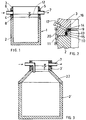
- FIG. 1 Various embodiments of the innovation are shown in the figures.
- the joint 8, which is shown on an enlarged scale in FIG. 2, is a tongue and groove connection descending to the outside with an inner horizontal (9) and a central vertical joint section 10.
- the outer horizontal joint section 11 serves to support the two concrete parts on one another.
- a ring (not shown) or a cone is placed on the ring 3 and, if necessary, one or more shaft rings are placed to reach the frost-free depth.
- the water line 12 is clearly visible above the joint 8, which is why the special shape of the permanently elastic seal shown in FIG. 2 is preferred.
- a two-part sealing ring 13 is inserted into the joint, which consists of two parts 14, 15 and a connecting web 16.
- the two concrete parts are additionally connected by means of clamping elements 20, so that the seal is not changed by earth movements. Due to this rigid connection, resin-bonded grout can also be used.
- the joint surfaces against which the mortar lies must be prepared for better adhesion.
- Fig. 3 differs from Fig. 1/2 in that the ring 3 'is placed on a shaft cone 22, which has already reduced the diameter of the lower part 2' to the width of the maintenance shaft.
- the inlet pipe is angled downward after the wall flange, so that the inlet flow is directed downward and braked.
- the water level is again at the level of the outlet spout 7.
- the embodiment according to FIG. 4 likewise has a shaft cone 27 ', which, however, already has the function of an attachment ring which increases the volume. Because inlet and outlet 6 ', 7' already open into this shaft cone, and specifically at the angle of the shaft cone. Accordingly, almost the full diameter of the pool is used for the time spent here.
- a cylindrical ring 3 ' is inserted between the lower part of the basin 2' 'and a flat cover plate 23, which increases the available sludge trap volume upwards.
- Inlet and outlet lines 26, 27 are led downwards through the wall of the basin lower part 2 ′′ (so-called jump tubes).
- the inside of the outlet pipe is raised as far as the water level should be.
- the outer overflow threshold in the outlet pipe can be at the same level or below.
Landscapes
- Health & Medical Sciences (AREA)
- Life Sciences & Earth Sciences (AREA)
- Engineering & Computer Science (AREA)
- Hydrology & Water Resources (AREA)
- Public Health (AREA)
- Water Supply & Treatment (AREA)
- Filling Or Discharging Of Gas Storage Vessels (AREA)
- Forms Removed On Construction Sites Or Auxiliary Members Thereof (AREA)
- Moulding By Coating Moulds (AREA)
- Sewage (AREA)
Applications Claiming Priority (2)
| Application Number | Priority Date | Filing Date | Title |
|---|---|---|---|
| DE9408235U DE9408235U1 (de) | 1994-05-19 | 1994-05-19 | Abscheider in Form eines aus bewehrtem Beton hergestellten Beckens |
| DE9408235U | 1994-05-19 |
Publications (2)
| Publication Number | Publication Date |
|---|---|
| EP0683277A2 true EP0683277A2 (fr) | 1995-11-22 |
| EP0683277A3 EP0683277A3 (fr) | 1997-01-15 |
Family
ID=6908830
Family Applications (1)
| Application Number | Title | Priority Date | Filing Date |
|---|---|---|---|
| EP95104173A Withdrawn EP0683277A3 (fr) | 1994-05-19 | 1995-03-22 | Séperateur du type bassin de béton armé. |
Country Status (2)
| Country | Link |
|---|---|
| EP (1) | EP0683277A3 (fr) |
| DE (1) | DE9408235U1 (fr) |
Families Citing this family (3)
| Publication number | Priority date | Publication date | Assignee | Title |
|---|---|---|---|---|
| DE29805419U1 (de) * | 1998-03-25 | 1998-05-28 | Lauterbach-Kießling GmbH, 95517 Seybothenreuth | Mehrkammerbehälter für Kleinkläranlagen |
| DE29901937U1 (de) | 1999-02-04 | 1999-07-15 | Passavant-Werke Ag, 65326 Aarbergen | Leichtflüssigkeitsabscheider in Kompaktbauweise |
| EP2500476A1 (fr) * | 2011-03-17 | 2012-09-19 | Kessel AG | Système de séparation avec collecteur échangeable |
Family Cites Families (4)
| Publication number | Priority date | Publication date | Assignee | Title |
|---|---|---|---|---|
| FR1556628A (fr) * | 1968-03-04 | 1969-02-07 | ||
| US3826376A (en) * | 1973-08-20 | 1974-07-30 | Carlson & Sons A | Septic tank construction |
| GB2011975B (en) * | 1977-12-21 | 1982-09-15 | Malglen Concrete Tanks Ltd | Sewage disposal apparatus |
| DE3904321A1 (de) * | 1989-02-14 | 1990-08-16 | Passavant Werke | Abscheider fuer leicht- und/oder sinkstoffe mit schachtaufbau |
-
1994
- 1994-05-19 DE DE9408235U patent/DE9408235U1/de not_active Expired - Lifetime
-
1995
- 1995-03-22 EP EP95104173A patent/EP0683277A3/fr not_active Withdrawn
Also Published As
| Publication number | Publication date |
|---|---|
| DE9408235U1 (de) | 1994-08-04 |
| EP0683277A3 (fr) | 1997-01-15 |
Similar Documents
| Publication | Publication Date | Title |
|---|---|---|
| DE3204888C2 (de) | Kontrollschacht für eine unterirdische Abwasser-Kanalisation | |
| KR100485742B1 (ko) | 우수 저류조 | |
| DE2026066A1 (de) | Schwimmbeckenskimmer und Regelgerat | |
| EP0683277A2 (fr) | Séperateur du type bassin de béton armé | |
| DE102012203818B4 (de) | Bodeneinsatz für Schachtbauwerke | |
| DE19804160B4 (de) | Selbsttätig wirkende Stoßentleerungsvorrichtung | |
| DE8909733U1 (de) | Leichtflüssigkeitsabscheider | |
| DE19714739A1 (de) | Regenwasserspeicher | |
| DE4321557A1 (de) | Verfahren zum Erstellen von Becken für die Abwasserbehandlung | |
| JP2022182880A (ja) | 雨水貯留浸透施設および雨水貯留浸透施設の堆砂滞留板 | |
| DE202006015139U1 (de) | Kunststoffbehälter | |
| KR101854161B1 (ko) | 교량용 배수 장치 | |
| RU2801091C1 (ru) | Дренажно-фильтрующее щелевое устройство для обезвоживания жидких шламов (варианты) | |
| RU2789579C2 (ru) | Дренажно-фильтрующее щелевое устройство для обезвоживания жидких шламов, образующихся на очистных сооружениях в процессах очистки сточных вод (варианты) | |
| DE6925286U (de) | Abscheider fuer leichtstoffe | |
| KR101528834B1 (ko) | 탈부착형 거름망을 구비한 맨홀과 경사면을 형성하는 블록을 사용한 조립식 빗물저장시설 | |
| JPS59669B2 (ja) | 仮設便所 | |
| DE8005152U1 (de) | Aus fertigteilringen zusammengesetzter kanalschacht, bei dem die beispielsweise aus beton, stahlbeton oder auch kunststoff bestehenden fertigteilringe unter zwischenschaltung von dichtungseinlagen aufeinanderliegen | |
| DE202011109715U1 (de) | Langlebige Versickerungskästen zum Aufbau einer hochbelastbaren Wasserversickerungsanordnung | |
| DE7620785U1 (de) | Geruchsverschluss fuer sanitaer-anlagen, insbesondere fuer urinalanlagen | |
| GB2629754A (en) | Access chambers | |
| EP1762289A2 (fr) | Dispositif de sédimentation | |
| DE9400741U1 (de) | Flüssigkeitsbehälter zum Sammeln und Speichern von Flüssigkeiten, insbesondere von Regenwasser | |
| DE4401252A1 (de) | Flüssigkeitsbehälter zum Sammeln und Speichern von Flüssigkeiten, insbesondere von Regenwasser | |
| CN207003564U (zh) | 学生食堂用洗碗槽 |
Legal Events
| Date | Code | Title | Description |
|---|---|---|---|
| PUAI | Public reference made under article 153(3) epc to a published international application that has entered the european phase |
Free format text: ORIGINAL CODE: 0009012 |
|
| AK | Designated contracting states |
Kind code of ref document: A2 Designated state(s): AT BE CH DE DK ES FR GB GR IE IT LI LU NL PT SE |
|
| PUAL | Search report despatched |
Free format text: ORIGINAL CODE: 0009013 |
|
| AK | Designated contracting states |
Kind code of ref document: A3 Designated state(s): AT BE CH DE DK ES FR GB GR IE IT LI LU NL PT SE |
|
| STAA | Information on the status of an ep patent application or granted ep patent |
Free format text: STATUS: THE APPLICATION HAS BEEN WITHDRAWN |
|
| 18W | Application withdrawn |
Withdrawal date: 19970206 |