EP0683287B1 - Profilschiene zur Befestigung flächiger Gegenstände - Google Patents
Profilschiene zur Befestigung flächiger Gegenstände Download PDFInfo
- Publication number
- EP0683287B1 EP0683287B1 EP95810283A EP95810283A EP0683287B1 EP 0683287 B1 EP0683287 B1 EP 0683287B1 EP 95810283 A EP95810283 A EP 95810283A EP 95810283 A EP95810283 A EP 95810283A EP 0683287 B1 EP0683287 B1 EP 0683287B1
- Authority
- EP
- European Patent Office
- Prior art keywords
- clamping
- profile
- profile bar
- clamping edges
- edges
- Prior art date
- Legal status (The legal status is an assumption and is not a legal conclusion. Google has not performed a legal analysis and makes no representation as to the accuracy of the status listed.)
- Expired - Lifetime
Links
- 229910000838 Al alloy Inorganic materials 0.000 claims abstract description 4
- 238000005253 cladding Methods 0.000 claims description 5
- 238000004519 manufacturing process Methods 0.000 claims description 3
- 230000000694 effects Effects 0.000 description 9
- 238000010276 construction Methods 0.000 description 3
- 239000000463 material Substances 0.000 description 3
- 230000003068 static effect Effects 0.000 description 3
- 239000000853 adhesive Substances 0.000 description 2
- 230000001070 adhesive effect Effects 0.000 description 2
- 238000009415 formwork Methods 0.000 description 2
- 238000009413 insulation Methods 0.000 description 2
- 238000004026 adhesive bonding Methods 0.000 description 1
- XAGFODPZIPBFFR-UHFFFAOYSA-N aluminium Chemical compound [Al] XAGFODPZIPBFFR-UHFFFAOYSA-N 0.000 description 1
- 229910052782 aluminium Inorganic materials 0.000 description 1
- 238000005452 bending Methods 0.000 description 1
- 230000005489 elastic deformation Effects 0.000 description 1
- 238000003780 insertion Methods 0.000 description 1
- 230000037431 insertion Effects 0.000 description 1
- 230000007774 longterm Effects 0.000 description 1
Images

Classifications
-
- E—FIXED CONSTRUCTIONS
- E04—BUILDING
- E04B—GENERAL BUILDING CONSTRUCTIONS; WALLS, e.g. PARTITIONS; ROOFS; FLOORS; CEILINGS; INSULATION OR OTHER PROTECTION OF BUILDINGS
- E04B9/00—Ceilings; Construction of ceilings, e.g. false ceilings; Ceiling construction with regard to insulation
- E04B9/06—Ceilings; Construction of ceilings, e.g. false ceilings; Ceiling construction with regard to insulation characterised by constructional features of the supporting construction, e.g. cross section or material of framework members
- E04B9/064—Ceilings; Construction of ceilings, e.g. false ceilings; Ceiling construction with regard to insulation characterised by constructional features of the supporting construction, e.g. cross section or material of framework members comprising extruded supporting beams
-
- E—FIXED CONSTRUCTIONS
- E04—BUILDING
- E04B—GENERAL BUILDING CONSTRUCTIONS; WALLS, e.g. PARTITIONS; ROOFS; FLOORS; CEILINGS; INSULATION OR OTHER PROTECTION OF BUILDINGS
- E04B9/00—Ceilings; Construction of ceilings, e.g. false ceilings; Ceiling construction with regard to insulation
- E04B9/22—Connection of slabs, panels, sheets or the like to the supporting construction
- E04B9/24—Connection of slabs, panels, sheets or the like to the supporting construction with the slabs, panels, sheets or the like positioned on the upperside of, or held against the underside of the horizontal flanges of the supporting construction or accessory means connected thereto
- E04B9/26—Connection of slabs, panels, sheets or the like to the supporting construction with the slabs, panels, sheets or the like positioned on the upperside of, or held against the underside of the horizontal flanges of the supporting construction or accessory means connected thereto by means of snap action of elastically deformable elements held against the underside of the supporting construction
-
- E—FIXED CONSTRUCTIONS
- E04—BUILDING
- E04F—FINISHING WORK ON BUILDINGS, e.g. STAIRS, FLOORS
- E04F13/00—Coverings or linings, e.g. for walls or ceilings
- E04F13/07—Coverings or linings, e.g. for walls or ceilings composed of covering or lining elements; Sub-structures therefor; Fastening means therefor
- E04F13/08—Coverings or linings, e.g. for walls or ceilings composed of covering or lining elements; Sub-structures therefor; Fastening means therefor composed of a plurality of similar covering or lining elements
- E04F13/0801—Separate fastening elements
- E04F13/0803—Separate fastening elements with load-supporting elongated furring elements between wall and covering elements
-
- E—FIXED CONSTRUCTIONS
- E04—BUILDING
- E04F—FINISHING WORK ON BUILDINGS, e.g. STAIRS, FLOORS
- E04F13/00—Coverings or linings, e.g. for walls or ceilings
- E04F13/07—Coverings or linings, e.g. for walls or ceilings composed of covering or lining elements; Sub-structures therefor; Fastening means therefor
- E04F13/08—Coverings or linings, e.g. for walls or ceilings composed of covering or lining elements; Sub-structures therefor; Fastening means therefor composed of a plurality of similar covering or lining elements
- E04F13/12—Coverings or linings, e.g. for walls or ceilings composed of covering or lining elements; Sub-structures therefor; Fastening means therefor composed of a plurality of similar covering or lining elements of metal or with an outer layer of metal or enameled metal
Definitions
- the present invention relates to a Profile rail for fastening flat objects, especially facade elements, according to the preamble of Claim 1.
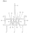
- the profile rail 1 shows the profiled rail 1 according to the invention in the floor plan, see also Fig. 6.
- This rail is for fastening facade elements, such as shown in Fig. 6, thought and points in this case one or more fastening tabs 2 on the can be designed differently or in the case of one Apparatus construction or a connecting rail too are unnecessary.
- the profile rail has a central profile 3 and then a side profile 4 on both sides or 5 on. Between the two side profiles and the The central profile is a continuous clamping groove 6 or 7, designed.
- the profile rail can also be one of two have different number of clamping grooves.
- the groove width, or the design of the groove cross section is such that the clamping effect achieved is sufficient is large, as inserted therein according to FIGS. 2-6 Pages of facade elements or walkways of apparatus to be able to pinch without usually additional Need fasteners. To make this strong There are various measures to achieve a clamping effect been hit.
- a first measure is that all three profiles are designed as hollow profiles, due to the elasticity of the material, for example extruded aluminum alloy, a resilient effect of the walls involved is achieved.
- a the second measure is the design of the two Clamp walls.
- the symmetrically constructed central profile 3 has two Clamping walls 8 and 9, each of which is a medium, symmetrical clamping edge 10 or 11 and an outer, has asymmetrical clamping edge 12 or 13, the two outer clamping edges more the guidance of the corresponding part of the object to be clamped than the actual clamping.
- the cavity 14 in Central profile sits laterally to the two middle ones Clamping edges 10 and 11 away, so that these clamping edges not consist of a full profile, but by the cavity contained therein a better spring action is achieved. This spring effect is further supported due to the inwardly convex shape of the clamping walls 8, 9.
- the two clamping walls 8 and 9 are opposite Side clamping walls 15 and 16 of the two side profiles 4 and 5. Located offset from the clamping edges 10 and 11 asymmetrical on the side walls, barbed first 17, 18 and second Clamping edges 19, 20. The second clamping edges are located at a distance from the middle clamping edges inwards, i.e. towards the mounting bracket 2. The middle clamping edges 10, 11 and the associated first and second clamping edges 17, 19 and 18, 20 respectively together a clamp in the manner of a three-point support, the Guide through the outer clamping edges 12, 13 on Central profile 3 is reinforced.
- the side profiles 4 and 5 are approximate on average designed square, the respective clamping walls 15, 16 from the middle clamping edge 10, 11 outwards, i.e. are beveled away from the central profile 3 like a funnel.
- a C-shaped closes on both sides of the side profiles 4, 5 Attachment profile 21 or 22 to other parts to record.
- FIG. 2 it is shown that for many applications the simple insertion of facade elements 23 in the clamping grooves 6, 7 are adequately fastened Elements.
- Fig. 3 it is stated that the Facade elements 23 additionally or exclusively can be secured at certain intervals a fastening screw 24 in the central profile 3 across to the connection plane between edges 10 and 11 can be introduced. This creates a force generate through which the middle clamping edges 10, 11th be spread apart. This allows the Clamping effect of the clamping grooves 6, 7 can be increased massively.
- Fig. 4 is another variant of securing Facade elements shown, the side walls 25 of the Elements 26 have cams or barbs 27 behind the suitably undercut, outer clamping edges 12, 13 grip the facade elements 23 in the profile strip 1 fasten securely.
- 5 is a further variant gluing the facade elements 23 using an adhesive 28 shown.
- the invention is not based on the fastening of facade elements limited and instead such elements can also be webs, side walls, panels, Flat parts or legs of apparatus or the like in the clamping grooves 6, 7 are inserted to this fasten.
- apparatus which is usually the Use profile rail 1 as a construction rib other fastening tabs are provided on the profile rail, or other fasteners to attach the mounting rail to the To be attached to the wall or to another component.
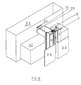
- FIG. 6 is a perspective view and partially cut the attachment of jammed Facade elements 23 in the rail 1 on one Substructure based on the static base 33 of a building is shown.
- the Fastening tab 2 of the rail 1 is on one Fastening piece 29 attached via a Insulation layer 30 with the static surface by means of for example, a screw 31 is anchored.
- Behind the An insulation layer 32 is arranged on facade elements.
- the Fastening device according to the invention is particularly suitable is, facade elements or apparatus cladding or the like without visible fasteners on a Attach substructure.
- Use cases can be extremely easy by simply clamping it into the profile rail be carried out, with any necessary additional security measures carried out very easily can be in the holes provided Screws 24 are screwed in or some adhesive 28 the parts to be inserted is attached.
- Screws 24 are screwed in or some adhesive 28 the parts to be inserted is attached.
Landscapes
- Engineering & Computer Science (AREA)
- Architecture (AREA)
- Civil Engineering (AREA)
- Structural Engineering (AREA)
- Physics & Mathematics (AREA)
- Electromagnetism (AREA)
- Clamps And Clips (AREA)
- Finishing Walls (AREA)
- Crystals, And After-Treatments Of Crystals (AREA)
- Joining Of Building Structures In Genera (AREA)
- Paper (AREA)
- Gripping Jigs, Holding Jigs, And Positioning Jigs (AREA)
- Slide Fasteners, Snap Fasteners, And Hook Fasteners (AREA)
- Supports Or Holders For Household Use (AREA)
- Absorbent Articles And Supports Therefor (AREA)
- Connection Of Plates (AREA)
Description
- Fig. 1
- zeigt im Grundriss ein erstes Ausführungsbeispiel der Erfindung,
- die Fig. 2 - 5
- zeigen vier verschiedene Anwendungsmöglichkeiten der Befestigungsvorrichtung für Fassadenelemente, und
- Fig. 6
- zeigt in perspektivischer Sicht und teilweise geschnitten die Verwendung der Vorrichtung gemäss Fig. 1 an einem statischen Untergrund.
Claims (13)
- Profilschiene (1) zur Befestigung flächiger Gegenstände, insbesondere Fassadenelementen (23),dadurch gekennzeichnet,mit einem Zentralprofil (3) und zwei beidseitig benachbarten Seitenprofilen (4, 5), die starr miteinander verbunden sind und zwischen sich zwei Klemmnuten (6, 7) einschliessen,mit Klemmkanten (10, 12, 17, 19; 11, 13, 18, 20) an den Profilen (3, 4, 5), die gegen das Innere der Klemmnuten (6, 7) weisen,wobei die flächigen Gegenstände etwa rechtwinklig abgekantete Seitenwände (25) aufweisen, welche im wesentlichen geradlinig in die Klemmnuten (6, 7) eingeschoben und durch die Klemmkanten (10, 12, 17, 19; 11, 13, 18, 20) fixiert sind,
dass jede der beiden Klemmnuten (6, 7) wenigstens drei Klemmkanten (10, 12, 17, 19; 11, 13, 18, 20) aufweist, und dass die Klemmkanten (10, 12, 17, 19; 11, 13, 18, 20) auf die beiden Seiten der Klemmnuten (6, 7) verteilt, räumlich gegeneinander versetzt und bezüglich ihres Abstandes auf die Dicke der Seitenwände (25) der flächigen Gegenstände so abgestimmt bzw. so angeordnet sind, dass die in jeweils eine der Nuten (6, 7) geradlinig eingeschobenen Seitenwände (25) selbständig gehalten werden. - Profilschiene nach Anspruch 1,
dadurch gekennzeichnet,
dass jede Klemmnut (6, 7) drei Klemmkanten (10, 17, 19; 11, 18, 20) aufweist. - Profilschiene nach Anspruch 1,
dadurch gekennzeichnet,
dass jede Klemmnut (6, 7) vier Klemmkanten (10, 12, 17, 19; 11, 13, 18, 20) aufweist. - Profilschiene nach Anspruch 1,
dadurch gekennzeichnet,
dass die Klemmnuten (6, 7) sich von aussen nach innen trichterförmig verengen. - Profilschiene nach Anspruch 1,
dadurch gekennzeichnet,
dass die Klemmkanten (12, 17, 19; 13, 18, 20) widerhakenförmig ausgebildet sind. - Profilschiene nach Anspruch 1,
dadurch gekennzeichnet,
dass die Klemmkanten (12, 13) ausgebildet sind zum Hintergreifen von an den Seitenwänden (25) der flächigen Gegenstände angeordneten Widerhaken (27). - Profilschiene nach Anspruch 1,
dadurch gekennzeichnet,
dass das Zentralprofil (3) und die Seitenprofile (4, 5) Hohlprofile sind. - Profilschiene nach Anspruch 7,
dadurch gekennzeichnet,
dass die Klemmkanten (10, 11) zusammen mit dem Zentralprofil (3) als Hohlprofil ausgebildet sind. - Profilschiene nach Anspruch 8,
dadurch gekennzeichnet,
dass das Zentralprofil (3) so ausgebildet ist, dass durch eine Kraft quer zur Verbindungsebene durch die beiden Klemmkanten (10, 11) sich der Abstand der beiden Klemmkanten (10, 11) vergrössert. - Profilschiene nach Anspruch 9,
dadurch gekennzeichnet,
dass Schrauben (24) und zugeordnete Schraubgewinde im Zentralprofil (3) vorgesehen sind zur Erzeugung der genannten Kraft. - Profilschiene nach Anspruch 1,
dadurch gekennzeichnet,
dass sich an den Seitenprofilen (4, 5) C-förmige Befestigungsprofile (21, 22) anschliessen. - Profilschiene nach Anspruch 1,
dadurch gekennzeichnet,
dass eine Befestigungslasche (2) vorgesehen ist, die in der Ebene des Zentralprofils (3) liegt. - Profilschiene nach Anspruch 1,
dadurch gekennzeichnet,
dass als Material eine strangpressbare Aluminiumlegierung vorgesehen ist.
Applications Claiming Priority (2)
| Application Number | Priority Date | Filing Date | Title |
|---|---|---|---|
| CH1516/94 | 1994-05-16 | ||
| CH151694 | 1994-05-16 |
Publications (2)
| Publication Number | Publication Date |
|---|---|
| EP0683287A1 EP0683287A1 (de) | 1995-11-22 |
| EP0683287B1 true EP0683287B1 (de) | 1998-08-12 |
Family
ID=4212274
Family Applications (1)
| Application Number | Title | Priority Date | Filing Date |
|---|---|---|---|
| EP95810283A Expired - Lifetime EP0683287B1 (de) | 1994-05-16 | 1995-05-01 | Profilschiene zur Befestigung flächiger Gegenstände |
Country Status (8)
| Country | Link |
|---|---|
| US (1) | US5579624A (de) |
| EP (1) | EP0683287B1 (de) |
| AT (1) | ATE169711T1 (de) |
| CA (1) | CA2148861A1 (de) |
| CZ (1) | CZ123695A3 (de) |
| DE (1) | DE59503121D1 (de) |
| HU (1) | HU213777B (de) |
| PL (1) | PL175723B1 (de) |
Families Citing this family (43)
| Publication number | Priority date | Publication date | Assignee | Title |
|---|---|---|---|---|
| FR2754286B1 (fr) * | 1996-10-08 | 1998-12-31 | Monopanel Sa | Element pour facade avec parement decoratif |
| US5845447A (en) * | 1997-04-23 | 1998-12-08 | Armstrong World Industries, Inc. | Suspension ceiling system |
| US6101777A (en) * | 1997-04-23 | 2000-08-15 | Armstrong World Industries, Inc. | Suspension ceiling system |
| DE19720811A1 (de) * | 1997-05-16 | 1998-11-19 | Neher Systeme Gmbh & Co Kg | Anschlußrahmen für eine Fassadenkonstruktion |
| US6035598A (en) * | 1997-09-15 | 2000-03-14 | United Attachment Systems, Inc. | Composite panel attachment system |
| US5916100A (en) * | 1997-12-12 | 1999-06-29 | ? Elward Systems Corporation | Method and apparatus for erecting wall panels |
| US6170213B1 (en) | 1998-01-13 | 2001-01-09 | Dfb Sales, Inc. | Wall panel mounting system and method |
| IT1317120B1 (it) * | 2000-03-07 | 2003-05-27 | Politec Polimeri Tecnici Sa | Assieme di pannelli e di elementi di giunzione |
| US6622434B1 (en) * | 2000-05-24 | 2003-09-23 | Wayne Kenneth Garrett | Safety enclosure shield panel support system |
| US20020092961A1 (en) | 2001-01-12 | 2002-07-18 | Gallis Anthony J. | Modular form tube and clamp system |
| US6631600B2 (en) * | 2002-02-04 | 2003-10-14 | Tapco International | Corner brick block |
| US7600349B2 (en) * | 2003-02-26 | 2009-10-13 | Unirac, Inc. | Low profile mounting system |
| WO2005021889A1 (de) * | 2003-08-21 | 2005-03-10 | Erwin Steiner | Vorrichtung zur befestigung von fassadenelementen an bauwerken |
| US7628386B2 (en) * | 2005-01-07 | 2009-12-08 | Payne Fence Products, Llc | Fence system |
| US7509776B2 (en) * | 2005-02-28 | 2009-03-31 | Arrow Group Industries, Inc. | Modular storage shed system |
| US7797865B2 (en) * | 2007-04-04 | 2010-09-21 | Ledstar Inc. | Changeable message sign structure |
| US20100077686A1 (en) * | 2008-09-26 | 2010-04-01 | Dockside Canvas Co. | Decorative display |
| US20100077688A1 (en) * | 2008-09-26 | 2010-04-01 | Dockside Canvas Co. | Decorative display |
| CA2747061C (en) * | 2008-12-19 | 2016-04-26 | Brunkeberg Industriutveckling Ab | A method for mounting facade elements on a multi-storey building |
| FR2948390B1 (fr) * | 2009-07-22 | 2016-09-02 | Normalu | Lisse a double enclenchement |
| EP2576939B1 (de) | 2010-05-28 | 2017-11-01 | The Diller Corporation | Verkleidungssystem für gebäudelaminate |
| US8534479B2 (en) * | 2011-03-16 | 2013-09-17 | Vanguard National Trailer Corporation | Container sidewall connector |
| US10253505B2 (en) | 2013-01-22 | 2019-04-09 | Henry H. Bilge | System for mounting wall panels to a wall structure and wall panels therefor |
| US9328518B2 (en) | 2013-01-22 | 2016-05-03 | Henry H. Bilge | Method and system for mounting wall panels to a wall |
| USD767980S1 (en) | 2013-01-22 | 2016-10-04 | Henry H. Bilge | Fastener extrusion |
| USD767981S1 (en) | 2013-01-22 | 2016-10-04 | Henry H. Bilge | Fastener extrusion |
| US8833015B2 (en) * | 2013-01-22 | 2014-09-16 | Henry H. Bilge | System for mounting wall panels to a wall structure |
| MX2016005586A (es) * | 2013-11-01 | 2016-07-21 | 9290 9043 Québec Inc | Sistema de techo suspendido y loseta para el mismo. |
| US9068353B1 (en) * | 2013-12-11 | 2015-06-30 | Pavel Kovalchuk | Dry joint wall cladding attachment system |
| US9328517B2 (en) | 2014-04-14 | 2016-05-03 | Henry H. Bilge | System for mounting wall panels to a supporting structure |
| USD778464S1 (en) | 2014-05-06 | 2017-02-07 | Henry H. Bilge | Wall panel |
| US8925271B1 (en) | 2014-05-15 | 2015-01-06 | Henry H. Bilge | System for mounting wall panels to a wall structure |
| USD746486S1 (en) | 2014-06-23 | 2015-12-29 | Henry H. Bilge | Wall panel |
| USD747005S1 (en) | 2014-06-23 | 2016-01-05 | Henry H. Bilge | Wall panel |
| USD746487S1 (en) | 2014-06-23 | 2015-12-29 | Henry H. Bilge | Wall panel |
| US9388576B2 (en) | 2014-07-02 | 2016-07-12 | John Bowen | Trim assembly for a flexible panel in a false ceiling |
| US9631372B1 (en) | 2015-03-24 | 2017-04-25 | Henry H. Bilge | Wall panels to be mounted to a wall structure |
| US9359770B1 (en) * | 2015-04-23 | 2016-06-07 | Henry H. Bilge | System for mounting wall panels to a wall |
| US10011997B1 (en) | 2016-02-18 | 2018-07-03 | Henry H. Bilge | System and method for mounting wall panels to a wall |
| US10982452B1 (en) * | 2020-07-31 | 2021-04-20 | Bond Formwork Systems, LLC | Secondary joist profile for grid systems |
| US11268289B2 (en) | 2020-07-31 | 2022-03-08 | Bond Formwork Systems, LLC | Drophead nut for formwork grid systems |
| US11047142B1 (en) | 2020-07-31 | 2021-06-29 | Bond Formwork Systems, LLC | Main beam structure and profile for formwork grid systems |
| DE102020127816A1 (de) * | 2020-10-22 | 2022-04-28 | 3A Composites Gmbh | Verkleidungssystem für eine Wand und Anordnung des Verkleidungssystems an einer Wand |
Family Cites Families (18)
| Publication number | Priority date | Publication date | Assignee | Title |
|---|---|---|---|---|
| US2023047A (en) * | 1933-05-17 | 1935-12-03 | Aluminum Co Of America | Tubular extruded shape |
| US2607971A (en) * | 1947-02-05 | 1952-08-26 | United Carr Fastener Corp | Panel fastener device |
| US3028192A (en) * | 1959-12-01 | 1962-04-03 | Great Dane Trailers Inc | Vehicle wall structure |
| CH413314A (de) * | 1963-01-16 | 1966-05-15 | Neveu Rene | Verbindungs- und Befestigungsmittel für aus Platten, Bändern und dergl. Materialien hergestellte Dach- und Wandverkleidungen |
| BE643160A (de) * | 1963-02-07 | |||
| CH459513A (de) * | 1967-07-12 | 1968-07-15 | Neveu Rene | Verbindungs- und Befestigungsmittel für aus Platten oder Bändern hergestellte Dach-, Decken- und Wandverkleidungen |
| US3729878A (en) * | 1971-06-25 | 1973-05-01 | Intern Environmental Dynamics | Curtain wall construction |
| BE789129A (fr) * | 1971-09-24 | 1973-01-15 | Dynamit Nobel Ag | Revetement de facade |
| US3918231A (en) * | 1972-02-15 | 1975-11-11 | Gerald Kessler | Frost resistant window sash |
| US4063393A (en) * | 1973-05-10 | 1977-12-20 | Toti Andrew J | Panel assembly structure and procedure for assembling same |
| US4332119A (en) * | 1979-03-05 | 1982-06-01 | Toews Norman J | Wall or panel connector and panels therefor |
| US4344267A (en) * | 1980-04-10 | 1982-08-17 | Carl Dunmon & Associates, Inc. | Apparatus for joining wall panels |
| DE3112746A1 (de) * | 1981-03-31 | 1982-10-21 | Ernst 4102 Binningen Koller | "profilstabfoermiges bauelement fuer gebaeude" |
| US4506484A (en) * | 1983-06-23 | 1985-03-26 | Construction Specialties, Inc. | Panel wall system |
| GB2135355B (en) * | 1983-02-11 | 1987-02-04 | Teal Claddings Limited | Cladding attachment assembly |
| DE3312150A1 (de) * | 1983-04-02 | 1984-10-11 | Eltreva Ag, Aesch | Fassadenverkleidung mit unterkonstruktion |
| US4829740A (en) * | 1987-10-19 | 1989-05-16 | Dunmon Corporation | Apparatus for joining wall panels |
| US5263292A (en) * | 1991-01-07 | 1993-11-23 | American Wall Products | Building panel system |
-
1995
- 1995-05-01 EP EP95810283A patent/EP0683287B1/de not_active Expired - Lifetime
- 1995-05-01 DE DE59503121T patent/DE59503121D1/de not_active Expired - Fee Related
- 1995-05-01 AT AT95810283T patent/ATE169711T1/de not_active IP Right Cessation
- 1995-05-08 HU HU9501349A patent/HU213777B/hu not_active IP Right Cessation
- 1995-05-08 CA CA002148861A patent/CA2148861A1/en not_active Abandoned
- 1995-05-09 US US08/438,657 patent/US5579624A/en not_active Expired - Fee Related
- 1995-05-12 CZ CZ951236A patent/CZ123695A3/cs unknown
- 1995-05-15 PL PL95308606A patent/PL175723B1/pl unknown
Also Published As
| Publication number | Publication date |
|---|---|
| PL308606A1 (en) | 1995-11-27 |
| HU9501349D0 (en) | 1995-06-28 |
| US5579624A (en) | 1996-12-03 |
| HUT72372A (en) | 1996-04-29 |
| HU213777B (en) | 1997-10-28 |
| PL175723B1 (pl) | 1999-02-26 |
| DE59503121D1 (de) | 1998-09-17 |
| ATE169711T1 (de) | 1998-08-15 |
| CA2148861A1 (en) | 1995-11-17 |
| EP0683287A1 (de) | 1995-11-22 |
| CZ123695A3 (en) | 1995-12-13 |
Similar Documents
| Publication | Publication Date | Title |
|---|---|---|
| EP0683287A1 (de) | Profilschiene zur Befestigung flächiger Gegenstände | |
| DE1927040C3 (de) | Vorrichtung zum stirnseitigen Anschluß eines Strangprofils an einem zumindest an der Verbindungsstelle durchlaufenden Strangprofil insbessondere aus Leicht metall, Kunststoff od dgl | |
| DE19751167C1 (de) | Profilstab | |
| DE69516003T2 (de) | Konstruktionssystem mit vorgefertigten lochanordnungen | |
| DD298299A5 (de) | Wandkonstruktionssystem | |
| EP2063047A1 (de) | Profilschienensystem | |
| EP0459033B1 (de) | Führungsschienensystem für Aufzüge | |
| EP0369326A2 (de) | Isolierende Verbindungsvorrichtung für Bauplatten | |
| EP0589380B1 (de) | Mutterartiges Element zum Festlegen in einem Innenraum | |
| DE3049346A1 (de) | Tragkonstruktion fuer unterdecken | |
| DE3213717A1 (de) | Flaechenelement zur bildung flaechiger gegenstaende, wie sichtblenden, und zum zusammensetzen von wand- und deckenteilen fuer messestaende oder dergleichen aufbauten | |
| DE2923903C2 (de) | ||
| DE2916003A1 (de) | Befestigungsvorrichtung, insbesondere fuer die verbindung von zwei bauteilen von bauwerken | |
| DE102018103311B3 (de) | Basisprofil einer Fußbodenprofilanordnung | |
| DE3241424C2 (de) | Verbindungseinrichtung | |
| DE10134396C1 (de) | Bausatz zum Einsetzen eines Wandelementes in eine Wandöffnung einer doppelschaligen Ständerwand | |
| EP3798379B1 (de) | Profilsystem und stellsystem sowie verfahren zur herstellung eines profilsystems und verwendung des profilsystems und/oder des stellsystems | |
| EP0623530A1 (de) | Hängefördereinrichtung mit einem Montageprofilsatz | |
| WO2002088482A1 (de) | T-verbindung zweier profilstäbe | |
| DE69815904T2 (de) | Klemmverbindungselement zum Verbinden zweier Wandprofile miteinander | |
| DE102017000924A1 (de) | Plattenhalter | |
| EP0846814B1 (de) | Montageschiene | |
| WO2006092156A1 (de) | Wandelement | |
| DE19531658B4 (de) | Stützvorrichtung für eine Kabelbahn | |
| DE4244143C2 (de) | Rahmengestell aus Rahmenschenkeln für einen Schaltschrank |
Legal Events
| Date | Code | Title | Description |
|---|---|---|---|
| PUAI | Public reference made under article 153(3) epc to a published international application that has entered the european phase |
Free format text: ORIGINAL CODE: 0009012 |
|
| AK | Designated contracting states |
Kind code of ref document: A1 Designated state(s): AT BE CH DE FR GB LI LU NL |
|
| 17P | Request for examination filed |
Effective date: 19960404 |
|
| GRAG | Despatch of communication of intention to grant |
Free format text: ORIGINAL CODE: EPIDOS AGRA |
|
| GRAG | Despatch of communication of intention to grant |
Free format text: ORIGINAL CODE: EPIDOS AGRA |
|
| GRAH | Despatch of communication of intention to grant a patent |
Free format text: ORIGINAL CODE: EPIDOS IGRA |
|
| 17Q | First examination report despatched |
Effective date: 19971230 |
|
| GRAH | Despatch of communication of intention to grant a patent |
Free format text: ORIGINAL CODE: EPIDOS IGRA |
|
| GRAA | (expected) grant |
Free format text: ORIGINAL CODE: 0009210 |
|
| AK | Designated contracting states |
Kind code of ref document: B1 Designated state(s): AT BE CH DE FR GB LI LU NL |
|
| REF | Corresponds to: |
Ref document number: 169711 Country of ref document: AT Date of ref document: 19980815 Kind code of ref document: T |
|
| REG | Reference to a national code |
Ref country code: CH Ref legal event code: NV Representative=s name: AMMANN PATENTANWAELTE AG BERN Ref country code: CH Ref legal event code: EP |
|
| GBT | Gb: translation of ep patent filed (gb section 77(6)(a)/1977) |
Effective date: 19980814 |
|
| REF | Corresponds to: |
Ref document number: 59503121 Country of ref document: DE Date of ref document: 19980917 |
|
| ET | Fr: translation filed | ||
| PLBE | No opposition filed within time limit |
Free format text: ORIGINAL CODE: 0009261 |
|
| STAA | Information on the status of an ep patent application or granted ep patent |
Free format text: STATUS: NO OPPOSITION FILED WITHIN TIME LIMIT |
|
| 26N | No opposition filed | ||
| PGFP | Annual fee paid to national office [announced via postgrant information from national office to epo] |
Ref country code: GB Payment date: 20000425 Year of fee payment: 6 |
|
| PGFP | Annual fee paid to national office [announced via postgrant information from national office to epo] |
Ref country code: LU Payment date: 20000504 Year of fee payment: 6 Ref country code: DE Payment date: 20000504 Year of fee payment: 6 |
|
| PGFP | Annual fee paid to national office [announced via postgrant information from national office to epo] |
Ref country code: CH Payment date: 20000524 Year of fee payment: 6 |
|
| PGFP | Annual fee paid to national office [announced via postgrant information from national office to epo] |
Ref country code: FR Payment date: 20000526 Year of fee payment: 6 |
|
| PGFP | Annual fee paid to national office [announced via postgrant information from national office to epo] |
Ref country code: NL Payment date: 20000531 Year of fee payment: 6 Ref country code: AT Payment date: 20000531 Year of fee payment: 6 |
|
| PGFP | Annual fee paid to national office [announced via postgrant information from national office to epo] |
Ref country code: BE Payment date: 20000717 Year of fee payment: 6 |
|
| PG25 | Lapsed in a contracting state [announced via postgrant information from national office to epo] |
Ref country code: LU Free format text: LAPSE BECAUSE OF NON-PAYMENT OF DUE FEES Effective date: 20010501 Ref country code: GB Free format text: LAPSE BECAUSE OF NON-PAYMENT OF DUE FEES Effective date: 20010501 Ref country code: AT Free format text: LAPSE BECAUSE OF NON-PAYMENT OF DUE FEES Effective date: 20010501 |
|
| PG25 | Lapsed in a contracting state [announced via postgrant information from national office to epo] |
Ref country code: LI Free format text: LAPSE BECAUSE OF NON-PAYMENT OF DUE FEES Effective date: 20010531 Ref country code: CH Free format text: LAPSE BECAUSE OF NON-PAYMENT OF DUE FEES Effective date: 20010531 Ref country code: BE Free format text: LAPSE BECAUSE OF NON-PAYMENT OF DUE FEES Effective date: 20010531 |
|
| BERE | Be: lapsed |
Owner name: UL TECH A.G. Effective date: 20010531 |
|
| PG25 | Lapsed in a contracting state [announced via postgrant information from national office to epo] |
Ref country code: NL Free format text: LAPSE BECAUSE OF NON-PAYMENT OF DUE FEES Effective date: 20011201 |
|
| GBPC | Gb: european patent ceased through non-payment of renewal fee |
Effective date: 20010501 |
|
| REG | Reference to a national code |
Ref country code: CH Ref legal event code: PL |
|
| PG25 | Lapsed in a contracting state [announced via postgrant information from national office to epo] |
Ref country code: FR Free format text: LAPSE BECAUSE OF NON-PAYMENT OF DUE FEES Effective date: 20020131 |
|
| NLV4 | Nl: lapsed or anulled due to non-payment of the annual fee |
Effective date: 20011201 |
|
| PG25 | Lapsed in a contracting state [announced via postgrant information from national office to epo] |
Ref country code: DE Free format text: LAPSE BECAUSE OF NON-PAYMENT OF DUE FEES Effective date: 20020301 |