EP0683292A1 - Zelt mit Rahmen - Google Patents
Zelt mit Rahmen Download PDFInfo
- Publication number
- EP0683292A1 EP0683292A1 EP94107547A EP94107547A EP0683292A1 EP 0683292 A1 EP0683292 A1 EP 0683292A1 EP 94107547 A EP94107547 A EP 94107547A EP 94107547 A EP94107547 A EP 94107547A EP 0683292 A1 EP0683292 A1 EP 0683292A1
- Authority
- EP
- European Patent Office
- Prior art keywords
- tent
- frame
- pole
- cover
- lateral
- Prior art date
- Legal status (The legal status is an assumption and is not a legal conclusion. Google has not performed a legal analysis and makes no representation as to the accuracy of the status listed.)
- Withdrawn
Links
- 238000009423 ventilation Methods 0.000 claims abstract description 17
- 238000005304 joining Methods 0.000 claims description 95
- 239000004744 fabric Substances 0.000 claims description 3
- 210000003128 head Anatomy 0.000 claims description 3
- 230000002787 reinforcement Effects 0.000 claims description 3
- 238000009434 installation Methods 0.000 claims 1
- 230000008901 benefit Effects 0.000 description 21
- 238000004519 manufacturing process Methods 0.000 description 14
- 229910000831 Steel Inorganic materials 0.000 description 12
- 239000010959 steel Substances 0.000 description 12
- 238000005452 bending Methods 0.000 description 9
- 239000000463 material Substances 0.000 description 8
- 239000003365 glass fiber Substances 0.000 description 6
- 230000009471 action Effects 0.000 description 5
- XAGFODPZIPBFFR-UHFFFAOYSA-N aluminium Chemical compound [Al] XAGFODPZIPBFFR-UHFFFAOYSA-N 0.000 description 5
- 229910052782 aluminium Inorganic materials 0.000 description 5
- 239000004411 aluminium Substances 0.000 description 5
- XLYOFNOQVPJJNP-UHFFFAOYSA-N water Substances O XLYOFNOQVPJJNP-UHFFFAOYSA-N 0.000 description 5
- 238000005192 partition Methods 0.000 description 3
- 230000002159 abnormal effect Effects 0.000 description 2
- 238000010276 construction Methods 0.000 description 2
- 238000001816 cooling Methods 0.000 description 2
- 230000033001 locomotion Effects 0.000 description 2
- 230000000149 penetrating effect Effects 0.000 description 2
- 230000009467 reduction Effects 0.000 description 2
- 238000005476 soldering Methods 0.000 description 2
- 229920002994 synthetic fiber Polymers 0.000 description 2
- 238000003466 welding Methods 0.000 description 2
- 241000167857 Bourreria Species 0.000 description 1
- 241000255925 Diptera Species 0.000 description 1
- 238000000429 assembly Methods 0.000 description 1
- 230000008859 change Effects 0.000 description 1
- 238000002474 experimental method Methods 0.000 description 1
- 238000012986 modification Methods 0.000 description 1
- 230000004048 modification Effects 0.000 description 1
- 230000035515 penetration Effects 0.000 description 1
- 238000000926 separation method Methods 0.000 description 1
- 238000003860 storage Methods 0.000 description 1
Images












Classifications
-
- E—FIXED CONSTRUCTIONS
- E04—BUILDING
- E04H—BUILDINGS OR LIKE STRUCTURES FOR PARTICULAR PURPOSES; SWIMMING OR SPLASH BATHS OR POOLS; MASTS; FENCING; TENTS OR CANOPIES, IN GENERAL
- E04H15/00—Tents or canopies, in general
- E04H15/32—Parts, components, construction details, accessories, interior equipment, specially adapted for tents, e.g. guy-line equipment, skirts, thresholds
- E04H15/34—Supporting means, e.g. frames
- E04H15/36—Supporting means, e.g. frames arch-shaped type
- E04H15/40—Supporting means, e.g. frames arch-shaped type flexible
Definitions
- This invention relates to a collapsible tent with frame, inner tent and at least one cover tent, especially for a small number of people, at which said inner tent and said at least partially elastic frame is so performed and detachable connected with each other, that they are stressed against one another, and said frame consists at least of two lateral forks, at these adjacent a front projecting range oblique front above, at said lateral forks adjacent each a front top section oblique to the rear above, at that adjacent each a rear top section, and at that adjacent each a rear lower section, and at said lateral forks adjacent each a front lower section, the latter consisting at least of one rod; at which the lateral forks are provided with at least each two joinings, and whose inner tent is preferably provided with a tent bottom with at least four below corners, and whose cover tent lies on the frame which is arched at least partially.
- Such tents are known as igloo tents or dome tents. They have the advantage of free interior and to be insensible to wind despite of the light construction as a result of their arched shape and the elastic frame.
- Their poles are composed of short rods by means of plug-joinings and elastic. These rods consists especially of aluminium or glass fibre.
- the poles are below provided with pins, which are placed in holes of flaps at the corners of the tent bottom, when the tent is erected.
- Problem 1A During the mounting operation, the inner tent and the frame are stressed against one another. Hereby the relative high frame is being overloaded, because the connection to the inner tent is firstly done with all force at one spot. Also the lower section of the frame is strongly loaded in case of wrong motions. Besides this, at the erected tend, said lower section has to transfer different outer forces, made by wind, from the top via the lateral forks to the ground.
- the rear top and lower sections of the usual continuous thin diagonal poles has not the desired exact position under the rear edge of the cover tent, thus under its seam.
- the cover tent does not look well as the result of the indifferent position of the rear sections of said diagonal poles.
- Problem 3 Large high tents for four or more people need a stronger broad frame for the broad tent bottom. Consequently the following problems result: Problem 3A: For a stronger frame, any connection of the frame's sections in the top is better for the stability of the frame.
- Problem 3B A stronger broad frame needs more hand power for the mounting operation. Therefore, it should have a special shape for easy mounting.
- Object 1 of the present invention is to create a light high tent with a frame, whose structure near the lateral forks is of equal resistance, stretching the inner tent; the latter having sufficient distance to the cover tent, so that both ones cannot touch, to avoid any penetrating of water under rain, or under hot weather, cooling air can circulate; in preferred embodiment withan about plane rear wall of the cover tent and an exact shape of its rear edges.
- Object 2 of the present invention is to create a high tent with a frame separated in several poles for easy mounting, whose front pole can be attached or detached in preferred embodiment by a single person, thus without any jamming of the front pole hereby; with exact positions of the bands on the frame.
- Object 3 of the present invention is to create a broad high tent with a strong frame, which is easily mountable in spite of its large size, in preferred embodiment by a single person.
- the invention seeks - in the previously mentioned objects 1 to 3 - to create tents with frame in which at least in anteroom or interior at least one person can stand upright (besides an example of a small tent for one person or perhaps two people).
- the invention solves the object concerning problem 1, that the inner tent is provided with a plane front area with at least an inner entry, and in front above with at least one front top corner, the latter with at least one front top string or band directed to the front, which is connected especially by means of hooks directly or indirectly with the front projecting range of the frame, and the frame is composed of several rods with different strengths, which are detachably connected by means of plug-joinings or by any different manner, at which the rods beside the lateral forks have a larger strength than the most different rods, at which in preferred embodiment also the rods in the rear lower section have a larger strength than the most different rods.
- the invention solves the object concerning problem 2, that the frame , in the collapsed condition of the tent, is separated in a front pole consisting of the front projecting range; and separate from it two diagonal poles each composed of a lateral fork, a front lower section, a front top section, a rear top section and a rear lower section; at which the poles each are hold inside together especially by means of stressing elastic, at which the front joining of each lateral fork has a larger clearance than the different plug-joinings, and said both diagonal poles are provided before their crossing point C with at least each a stop, which may be performed as a ball-joint, and the inner tent is above provided with at least a front top corner or two centre top corners with two main-bands, which are hung by means of top snap hooks or different connection parts in the diagonal poles before their stops, and said inner tent is also provided with at least two rear top corners with two rear top bands, which are hung by means of rear snap hooks or different connection parts in
- the invention solves the object concerning problem 3, that in the beginning of mounting operation of the tent a ring-pole exists, in which is present in the shape of a ring at least the front projecting range, both lateral forks, both front top sections, and a crossing-piece with at least four joinings, or five joinings, which may be connected by means of a centre cross rod, so that a crossing-rod exists, perhaps with six joinings; and the inner tent in preferred embodiment is provided with at least a top centre corner and a centre band or two main bands, which are hung by means of hooks or different connection parts in eyes at the crossing-piece or at the crossing-rod, or beside them at the frame; and further top strings and especially hooks are present between inner tent and frame.
- the inner tent is created especially with a front plane area which can be stretched better than usual arched tents, and which is rigidly stretched in all directions by means of bands or strings at the corners of the inner tent. Said large front plane area of the inner tent allows a large comfortable inner entry.
- an additional advantage is the exact position of the diagonal poles in the sewed rear corner-edges of the cover tent also by their stronger rods in the rear lower sections.
- the diagonal poles, (as well as middle pole, if present) and inner tent are already being mounted. Now the front pole is firstly stuck without any load into one fork and then stressed in cross direction. It is bent by one hand and the other fork is bent by the other hand, till they can shoved one into another. This is under load possible by the well feeling large clearance between the front pole and the lateral forks. (This way, also the later detaching of the front pole is possible.)
- Inner tent and frame are now erected and stand without any connect ion by means of tent nails stroked in the ground.
- the cover tent is put over the frame.
- the cover tent is hung in the eyes of four flaps at the below corners of the inner tent.
- the tent can be fastened by tent nails on the earth ground.
- the complete mounting operation can be done by a single person alone.
- the disassembly of the tent is done about inversely as described.
- the snap hooks or hooks permit to hang off firstly the inner tent which remains dry.
- the cover tent and the frame are collapsed finally.
- Said frame gets its shape under the for top sections mainly by itself. Consequently the bands can be performed in long shape, because not essential for the shape of the frame. Therefore, sufficient distance is present between inner tent and cover tent with all the advantages.
- the tent bottom is fixed at the ground by means of tent nails.
- the ring-pole lies over it.
- Its behind front lower section is fixed at the behind front corner of the tent bottom by means of pin in hole.
- Now the before front lower section is pushed inside, so that the ring-pole is stressed in cross direction.
- the before front lower section is fixed at the frame also by means of pin in hole.
- the front ends of the diagonal poles are secured against any loosening by mistake during the mounting operation. As the result of this, one single person is able to mount alone the tent.
- Said open tent can be closed: Either closed by a long high front tent (from the following sub claim 6). Or closed by a short front tent at said tents having a especially a curved middle rod in the front pole. The latter is in this way less stressed by bending when mounted, in spite of the relative thick diameters of its rods.
- One tent can be used in two different conditions: Without or with the long front tent.
- Said tent can by used either under nice and warm weather in the open condition without any front tent, or under cold weather with front tent.
- Said tent is self-supporting in this condition, so that the erected tent can easily be moved inside the camping area to a better spot.
- sub claim 14 results a variable rear ventilation protecting the inner tent against any rain when opened, which can be closed partially or nearly completely.
- Figs. 488a and 489a show a car from the side and from the top, in sections Y-Y and Z-Z of each other.
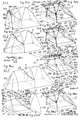
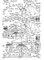
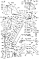
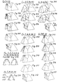
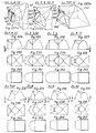
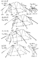
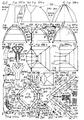
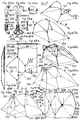
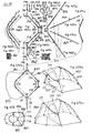
- Every tent 1 , 2 , 3 , 4 , 5 , 6 , 7 , 8 , 9 or 10 of the examples 1 to 10 shown in the figs. 1 to 8 is composed of a frame 11 , 12 , 13 , 17 , 18 , 19 or 20 illustraded in erected condition in the figs. 92a, 95a, 96a, 137a, 138a, 139a, 166a or 181a, and as shown in the figs.
- said tents 2, 3 and 8 shown in the figs. 2, 3 and 6 are composed of a separate front tent 42 , 43 or 48 , and an open tent 52 , 53 or similar 58 shown in the fig. 10, connected by means of a zipper 59 next the front top loop 60 of an "open cover tent” 62 , 63 or 68 , visible in the figs. 113a, 121a and 163a.
- the "open cover tent” 62, 63 or 68 and the front tent 42, 43 or 48 form now here each the complete cover tent 32, 33 or 38.
- the cover tent 69 and the frame 70 belong to the tent 71 example 7SP (sloped pointed).
- the simplest inner tent 29 is used in example 9 as shown in fig. 167a in half-ready manufactured condition. It is provided with four below corners 72 , 73 , 74 and 75 , a front top corner 76 , two front top below corners 77 , 78 and two rear top corners 79 , 80 .
- the different inner tents 21, 27 and 30 have each two top centre corners 81 and 82 .
- the inner tent 21 (examples 1, 2 and 3) shown in fig. 100a has two front top corners 83 , 84 and two additional side corners 85 .
- Said inner tent 29 in fig. 167a consists of a waterproof tent bottom 86 as well as plane walls of fabric subsequently mentioned: The sloping front area 87 , lateral areas 88 , 89 , two top side areas 90 , rear area 91 and top back area 92 . Straight edges 93 , 94 , 95 , 96 are between them.
- the different inner tents 21, 27 and 30 have an additional top area 97 .
- the inner tent 21 (examples 1, 2, 3) in fig. 100a has a plane vertical front area 98 and two additional side areas 99 .
- only one front top string 100 is also possible at the front top corner 76 of the inner tent 27 when used for tent 71 (example 7SP).
- two front top strings 101 , 102 (or bands) are fixed at the front top corner 76 or at the front top corners 83 and 84, as the inner tents 21, 27, 29 and 30 show in the figs. 101a, 142a, 168a and 183a.
- two front below strings 103 , 104 are placed, especially of elastic.
- top main-bands 105 and 106 are placed, either in fig. 168a fixed at the top corner 76, or in the figs. 101a, 142a and 183a at the top centre corners 81 and 82.
- the rear there are two rear top bands 107 and 108 at the rear top corners 79 and 80.
- the inner tent 21 in fig. 101a is provided with four vertical bands 116 , 117 , 118 and 119 at the front top corners 77, 78, 83, 84, and two side bands 120 , 121 .
- the ends of the front strings 100 to 104, of the lateral bands 111,112, and of the vertical bands 116 to 129 are each provided with different hooks 122 , and the ends of the other bands 105 to 110; 113, 114; 120, 121 with top snap hooks 123 , rear snap hooks 124 and front snap hooks 125 (or any different suited connection part).
- Every inner tent 21, 27, 29 and 30 is below provided with four flaps 127 , 128 , 129 , 130 with each a hole 131 , a semicircle eye 133 , and perhaps an additional upper semicircle eye 134 (figs. 40d and 46d) as well as some small loops 135 (fig. 39b), and in front provided with a curved zipper 136 or a middle zipper 137 , and with one or two horizontal zippers 139 , 140 for the inner entries 141 , 147 , 149 or 150 .
- the inner tents 21, 27, 29 and 30 are each provided with bands or burr bands not shown.
- the frames 11, 12 and 13 are each provided with equal (or symmetric) diagonal poles 151 and 152 .
- the similar frames of the tents 4, 5, 6 have each equal (or symmetric) diagonal poles 153 and 154 .
- the frames 17, 18, 70 (examples 7, 8, 7SP) have equal (or symmetric) diagonal poles 155 and 156 .
- the frame 19 (example 9) has equal (or symmetric) diagonal poles 157 , and 158 wand the frame 20 (example 10) equal (or symmetric) diagonal poles 159 and 160 .
- the frames 11, 12, 13, 17, 18, 19 or 20 are provided with different front poles 161 , 162 , 163 , 167 , 168 , 169 or 170 .
- the frames 11, 12 and 13 (examples 1, 2, 3) have an equal middle pole 171 .
- An additional second frame 173 is mounted in front of the frame 13 (example 3). All the lately specified rods of said frames and poles are connected by means of detachable plug-joinings 174 or 175 (used in fig. 59b for example) for different or equal rod diameter as illustrated in the figs. 262d, 266d; 274d, 277d.
- the erected frame 11 (example 1) is shown in the figs. 39b, 71b, 72b, as well as 92a in smaller size. In the figs. 49b to 70d the parts of said frame 11 are illustrated with one diagonal pole 151. The second diagonal pole 152 is equal or symmetric.
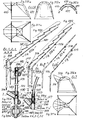
- the diagonal poles 151 and 152 consist each of a front lower section 176 , a lateral fork 177 (or each a symmetric lateral fork), a front top section 178 , a rear top section 179 , and a rear lower section 180 .
- the diagonal poles 151 and 152 are each composed of the following component parts shown in fig. 59k, beginning from said lateral fork 177 to the top: A stronger rod 183 , a strong rod 184 , a thin rod 185 , a separate double ball-joint 186 used at its front face 187 as a stop 188 , three thin rods 189 , 190 and 191 , a strong rod 192 , a strong(er) rod 193 , a strong rod 194 , a stressing elastic 195 continuously inside, and a plug 196 with a pin 197 .
- a much stronger rod 198 connected with said lateral fork 177, a stronger rod 199 , the said stressing elastic 195, and a plug 200 with pin 201 and head 202 having a cross hole 203 .
- the lateral forks 177 are each provided with a front joining 205 , a middle joining 206 , a rear joining 207 , a below joining 208 , and a rear eye 209 .
- the diagonal poles 151, 152 of the examples 1, 2, 3 may be performed without the ball-joint 186. Thus as shown in fig. 130a.
- the different diagonal poles 153,154; 155,156; 157,158 or 159, 160 (examples 4, 5, 6; 7, 8; 9; 10) shown in the figs. 130a, 147b, 171b and 186b are somewhat shorter. Besides 153, 154, they have each different lateral forks 217 , 219 or 220 without any middle joining, may be with each a top eye 221 (for any storm rope).
- the short poles 159,160 (example 10) shown in fig. 186b have thinner rods and each a normal plug 222 with a straight pin 223 in front below.
- the rod 185 is in the examples 4 to 10 provided with a fixed hull 224 shown in the figs. 148 d and 148 e . Its front face 187 is used as a stop 188.
- the middle pole 171 used in the frames 11, 12 and 13 (examples 1, 2, 3) shown in the figs. 68b,k is (beginning from its ends) composed of two plugs 225 , 226 connected with a continuously stressing elastic 227 inside, two curved strong rods 228 , 229 , and three curved inner rods 231 , 232 and 232 .
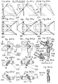
- the frames 11, 17, 19 and 20 are each provided with a similar front pole 161, 167, 169 or 170 which forms the front projecting range 234 of each frame, shown in the figs. 109a, 151a,b,k, 175a,b,k and 192a,b,k.
- fig. 52b beginning from its ends, it is each composed of two plugs 235 , 236 , connected by means of a continuously stressing elastic 237 inside, two stronger rods 239 , 240 , two strong rods 241 , 242 (except example 10), two rods 243 , 244 and a complete front cross rod 250 .
- the latter is shown in fig.
- each angle piece 257, 258 is provided with an eye 260 as well as with a hole 261 for the attaching of both equal separate front lateral rods 263 , 264 shown in the figs. 49b, 50b, 51d, 154a,b; 155a,b, 178a,b;179a,b and 195a,b; 196a,b, provided with a fixed hull 265 and two holes 266 .
- the frames 12 and 18 (examples 2, 8) have in the front projecting range 234 each another front pole 162 or 168 shown in the figs. 112a,b,k and 196a,b,k. Beginning from their ends, they are each composed of two plugs 271 , 272 , connected by a continuously stressing elastic 273 inside, two stronger rods 275 , 276 (in frame 18, consisting of different pipes 277 , 278 fixedly joined with each other), two strong rods 279 , 280 (except example 8), two rods 281 , 282 and a curved rod 283 in the middle.
- the frames 13 and 70 have each a similar front pole 163 or 290 shown in the figs. 116a,b,k and 156a,b,k. Beginning from their ends, they are each composed of two plugs 295 , 296 , connected by a continuously stressing elastic 297 inside, two stronger rods 299 , 300 , two strong rods 301 , 302 , (each) two rods 303 , 304 and one middle angle piece 305 . The latter is shown in the figs. 117d to 120d and 157d to 160d and is fixed on one next rod 303 and is provided with a hole 306 .
- This middle angle piece 305 is used either in the frame 70 (example 7SP) for the attaching of the middle front rod 307 (with hull 265 and two holes 266, like fig. 51d) shown in fig. 161a,b, or in the frame 13 (example 3) for the support of the second frame 173 subsequently described.
- the additional second frame 173 (example 3 as well as 16) is illustrated in the figs. 122a to 129d.
- its T-piece 310 is fixed at the strong longitudinal rod 311 .
- connection longitudinal rod 312 at which two hulls 313 , 314 and a short string 315 are fixed, as shown in fig. 128d.
- the latter is provided with a snap hook 316 .
- two strong rods 317 , 318 are laterally placed. Then each three rods 319 , 320 and two rods 321 , 322 .
- the ends of the second frame 173 are provided in the right, left and middle with equal plugs 323 , 324 and 325 having each a notch 326 and connected by means of a stressing elastic 327 inside.
- a long below cross string 328 is fixed having another snap hook 329 at its other end. Said both snap hooks 316 and 329 are suited for the mounting in said notches 326.
- the double ball-joint 186 shown in fig.67e is performed as a swivelling symmetric ball-hull 331 , having two holes 332 with larger diameters than the spherical movable ends of the next rods 185 and 189.
- the ball-hull 331 is provided with two inner cones 333 and two end cones 334 , and inside two front cones 335 (or a section of a ball as shown).
- the angle in this double ball-joint 186 may be smaller. Then its ball-hull 331 has a smaller diameter.
- the material of the rods mentioned previously is especially strong aluminium. But also different material may be used like glass-fibre, steel or any suited present or future material.
- the cover tents 31, 37, 39 and 40 (examples 1, 7, 9, 10 as well as 11, 12, 13) shown in the figs. 91a, 134a, 165a and 180a are in front above provided with each a front roof 340 hold by both front lateral rods 263, 264, and for the outer entries 341 , 347 , 349 , 350 with each a long zipper 351 and two top lateral short zippers 352 as shown in the figs. 251a and 254a as well as 252a and 255a with the variable front ventilation 353 in open condition of its air flap 354 . Then said front roof 340 protects it against any rain.
- the cover tent 71 (example 7SP) shown in fig.135a is in front above provided with a different front roof 356 hold by the middle front rod 307, and for the outer entry 357 with a long zipper 358 and one top lateral short zipper 359 as shown in the figs. 253a and 256a when the variable front ventilation 360 is opened by its air flap 361 .
- the figs. 221a, 222a and 223a show the below front part 362 of the previously mentioned cover tents 31, 37, 39, 40, 69 tied back under hot weather by means of each two bands 363 at them, especially with hooks 365 , 366 hung in the front pole 161, 167, 169, 170 or 290, or by means of burr bands.
- the "open cover tent” 62, 63 and 68 (examples 2, 3, 8 as well as 15, 16) shown in the figs. 113a, 121a and 163a are provided with two lateral triangles 371 , 372 with each a burr-band 373 at their ends, and each a corresponding burr-band 374 inside said "open cover tent” 62, 63 or 68, as well as in front above inside with four (semicircle) eyes 375 as shown in the figs. 114e, 140e.
- the "open cover tent” 63 (example 3, fig. 121a, as well as 15, 16) is provided with a middle break 376 in the front top loop 60 for the attaching of the second frame 173.
- the cover tents 31, 32, 33 and 38 (examples 1, 2, 3, 8 as well as different examples) as shown in the figs. 91a, 93a, 94a and 136a are back above in the interspace 379 provided with a variable rear ventilation 380 illustrated in the figs. 257a to 260a consisting of: An air flap 381 , two zippers 383 , 384 , two burr-bands 385 , 386 , and a sloping area 388 of waterproof fabric for the protection against any rain when opened as well as for the outside drainage of any water.
- cover tents 31, 32, 33, 37, 38, 39, 40 or 69 (examples 1 to 10, 7SP as well as examples 11, 13, 14) have bolow a nearly plane rear wall 390 .
- Every cover tent is especially of synthetic fabric or any different sheet material, and is as usually below provided with small loops for the tent nails and perhaps with hooks for the connection with the semicircle eyes 134 (figs. 40d and 46d) of the inner tent 21, 27, 29 or 30), here not shown. They are also provided with bands or burr bands not shown for the connection with its frame 11, 12, 13, 17, 18, 19, 20 or 70, or to hold open the outer entries 341, 344, 347, 348, 357; 412, 413 (as well as in the examples 11 to 16).
- the inner tent 21 (example 1) is spread on the earth ground.
- the front pins 201 of the diagonal poles 151, 152 are secured in the holes 131 of both front flaps 127, 128 of the tent bottom 86 either by means of two usual tent nails 395 crossly mounted in their cross holes 203, as illustrated in fig. 40d, or by any different suited short pegs.
- both small front snap hooks 125 of the front short bands 109, 110, placed about in half height in front of the inner tent 21, are hung in the eyes 209 of the lateral forks 177. Now the top snap hooks 123 and the rear snap hooks 124 are hung into the diagonal poles 151, 152 before and behind the stops 188. None can be loosened by any mistake during the mounting operation.
- FIG. 42d shows it for the hook 122 placed next a step 405 .
- Frame 11 and inner tent 21 are now erected and stand without any pegs, as can be seen in the figs. 39b and 88.
- both front lateral rods 263, 264 are attached into the holes 261 of the angle pieces 257, 258 at the front pole 161.
- the hooks 122 of the front top strings 101, 102 are now changed and hung in the holes 266 of the front lateral rods 263 and 264, as shown in fig. 76d.
- the latter are now secured by said hooks 122 and also the front roof 340.
- the tent 1 is illustrated in this position in the figs. 90 and 91a. If the cover tent 31 may be connected at the semicircle eyes 134 at the four flaps 127, 128, 129, 130 for this position, at least only four tent nails 395 are required to be stroke in the ground. Or more tent nails 395 are used as shown in the fig. 257a, also for the inner tent 21 there not shown.
- the hooks 122 and snap hooks 123, 124, 125 permit to hang off firstly the inner tent 21 from inside.
- the cover tent 31 with the frame 11 are standing provisionally. Under its protection, the inner tent 21 is folded up and remains dry. The cover tent 31 and the frame 11 are collapsed finally.
- the middle pole 171 exists only in the examples 1 to 6 (as well as in the examples 13, 15, 16). Hence in the different examples 7 to 10 the concerning section of the mounting operation cancels, thus in fig. 85.
- two front top strings 101, 102 are hung preferably in only one middle front rod 307 for reason of securing.
- the attaching of the short diagonal poles 159 and 160 is done in usual manner only by four straight normal pins 197 and 223 in front and rear.
- both lateral triangles 371, 372 of the "open cover tent" 62, 63 or 68 are connected around the frame 12, 13 or 18 by means of the burr-bands 373, 374 as shown in the figs. 115a and 164a.
- the front tent 42, 43 or 48 is connected by means of the zipper 59 also used as outer entry 412 or 413 as shown in the figs. 202, 203 as well as 205, 206 at one or both sides.
- the play in the plug-joinings 174 or 175 may be for example 0.2 mm. (But also any somewhat larger different play may exist.)
- the inner larger diameter l of any lateral fork may be 16 mm.
- the outer small diameter s may be 14 mm of the end of any front pole. This way, they can by easily mounted by their clearance of 2 mm, as already described, and really done on any erected tent according to the invention.
- the front pole may completely be mounted in the lateral fork also with this small clearance. But now it is impossible to detach it.
- the front pole is now fixed in the lateral fork as being welded.
- the clearance may be instead 2 mm also 1 mm or 3 mm or any similar value, depending of the size of the tent.
- Figs. 262d to 273d show the detachable plug-joining 174 as previously illustrated between the rods of different diameters (see fig. 59b), here shown between the rod-ends 420 , 421 by means of a short hull 422 fixed inside by lateral press 423 .
- Similar plug connections 424 , 425 and 426 are shown in the figs. 263d, 267d; 264d, 268d as well as 265d, 269d by means of a cut 427 , a notch 428 or a pin 429 .
- Figs. 274d to 281d show the detachable plug-joining 175 as illustrated in the frames between the rods of equal diameter (see also fig. 59b), here shown between the rod-ends 431 , 432 by means of a long hull 433 fixed outside by lateral press 434 .
- Similar plug connections 435 , 436 are shown in the figs. 275d, 278d by means of a long inner hull 437 , as well as in the figs. 276d, 279d by means of a reduced peg 438 .
- the figs. 282b to 286b show a front pole 440 which is a variant of the front pole 161 (or similar 167, 169, 170; example 1, similar example 7, 9, 10) illustrated in fig. 52b: Both front lateral rods 263 and 264 are now fixedly attached at the front cross rod 441 (instead of the complete front cross rod 250) especially made of steel, without any separate angle pieces 257, 258.
- Fig. 287b shows a front pole 442 (instead of the front pole 162 or similar 168, figs. 112b or 162b, examples 2, 8) without any middle curved rod 283. Instead of it, three thin rods 443 exist.
- the figs. 288b to 292b show a front pole 445 (instead of the front pole 290, fig. 156b, example 7SP): Now the middle front rod 307 is fixedly attached at the middle angle piece 305 especially made of steel, now angle rod 446 .
- the figs. 293b, 293k, 294d and 295d show a middle pole 450 (instead of the middle pole 171, fig. 68b, examples 1, 2, 3): Its inner rods 451 are now provided with reduced hulls 452 (fig. 294d) or additional intermediate hulls 453 between the outer hull 454 and the pipe 455 (fig. 295d). By this, a large play results among all the rods 451 and 456 . In unstressed condition, the front pole 450 can already be curved as illustrated in fig. 293b. Therefore, its rods 451 and 456 are less bent when mounted.
- Fig. 296b shows only one (longer) rod 458 below any lateral fork 217, 219, 220 or similar also 177. If made from steel, they may be one part. The latter may be used also when a second below rod is present.
- Fig. 297b shows a diagonal pole 460 which is a variant of the diagonal poles 151 or 152 (fig. 59b, examples 1, 2, 3), with two front rods 461 and three rear rods 462 of steel. And separate of this also here illustrated, said diagonal pole 460 with a second rear stop 463 . Also any different diagonal poles 153 to 158 may be performed in this way. (Two of said poles 460 with two stops 188 and 463 are shown in erected condition in fig. 354a.)
- Fig. 298b and 299e show a single ball-joint 464 fixedly connected with the thin rod 185 by means of press 465 , provided with an outer large notch 466 .
- Said single ball-joint 464 is also a stop 188 on the diagonal pole 467 and used instead of the double ball-joint 186.
- the inner details of said single ball-joint 464 are like the latter, shown in fig. 67e.
- both symmetric forks 469 and 470 are used in one frame (not shown) and illustrated in the figs. 302b and 303b. They are each provided with spherical oblique front joinings 471 , 472 , middle joinings 473 , 474 and rear joinings 475 , 476 and are variants of the two equal lateral forks 177 (figs. 60d, 61d, or similar forks 217, 219 or 220.
- the diagonal poles 151,152 and similar 153,154; 155,156 or 157,158 are each not equal, but symmetric.
- the advantage is, that the front pole 161 to 169 can by easily attached, because less bent and stressed during the mounting. But the disadvantage is, that in the beginning of mounting operation in fig. 82 attention is necessary to the right position of both different symmetric poles.
- Fig. 305b shows a long-hole 477 (with wide w ) which is the shape of the front joining 205 of the lateral fork 177 (figs. 60d, 61d) in the cross section R-R, or any different fork 217, 219 or 220.
- the figs. 307d to 309d show the plug-joining 174 between the rods 478 and 479 from glass fibre (or similar synthetic material) of different diameters by means of a reduction hull 480 , fixed especially at the thicker rod 479 by press.
- the diagonal pole 481 (of two equal diagonal poles in one frame) or 153, 154 (fig. 130a, examples 4, 5, 6) is a variant of the equal diagonal poles 151, 152 (fig. 59b, examples 1, 2, 3).
- the diagonal pole 481 is here without any ball-joint 168. It is provided with a upper fork 482 and a below fork 483 . They are connected by means a movable stronger intermediate rod 484 provided with each two larger cross holes 485 and 486 (or long holes).
- the forks 482, 483 are provided with small cross holes 487 , 488 , in which two pins 489 and 490 (more exaxtly clamping sleeves, or similar parts) are fixedly pressed, which catch each in the said each two larger holes 485, 486 of said both forks 482, 483, thus with twist play, as visible in fig. 320e.
- These and said intermediate rod 484 form together a fork-assembly 495 as shown in fig. 314d.
- the front, middle, rear and below joining 205, 206, 207 and 208 exist basically as already described.
- both diagonal poles 481 are equal, thus no change by mistake is possible during the mounting.
- each front joining 205 is swivelling to the rear joining 207 and get the desired position to inside (see fig. 311a) similar as gained by the symmetric forks 469 and 470 (see figs. 302b and 303b).
- the diagonal pole 481 is less bent and stressed when mounted by the higher position of its rear joining 207 (see fig. 310a) and its rear above shape becomes better.
- the cover tent 31 is above better supported by the frame 11, 12, 13 (see figs. 323a, 324a and 325a).
- the front joining 205 remains in its former height, consequently the front pole 161 can do its action as before.
- Fig. 315b shows the required new middle pole 497 , composed of the middle rod 498 and both lateral stronger rods 499 , which is illustrated in mounted condition in fig. 312a (in different scale) in the tent 1.
- Figs. 318b and 318k show a diagonal pole 504 which is a variant of the equal diagonal poles 155 and 156 (fig. 147b, examples 7, 7SP, 8). It is now provided with a stronger curved (or angular) rod 506 , fixedly connected with a reinforcement hull 507 by means of a small pin 508 (or by press). Rod 506 and hull 507 are movable mounted in the rear joining 207 (now almost vertically directed) and swivelling connected with the lateral fork 509 by means of a pin 510 fixed in two small cross holes 511 of it, similar as shown in fig. 320e.
- Said pin 510 is catching with play in two larger holes 512 of the curved rod 506 and the reinforcement hull 507.
- the latter and the curved rod 506 form together a fork-assembly 514 as shown in fig. 319d.
- the similar performed diagonal pole 518 in fig. 321b is a variant of the equal diagonal poles 157 and 158 (fig. 171b, example 9) and is in erected condition shown in fig. 329a.
- the next similar performed diagonal pole 519 in fig. 322b is a variant of the equal diagonal poles 159 and 160 (186b, example 10) and is erected shown in fig. 330a.
- the self-stressing symmetric forks 521 (before, also in section D-D in fig. 343d shown) and 522 (behind) are variants of the equal lateral forks 177 in the diagonal poles 151, 152 (figs. 59d, 61d, examples 1, 2, 3), which are now differently performed, because symmetric.
- Said symmetric forks 521 or 522 are each composed of a symmetric fork-body 523 or 524 , a swivelling front joining 525 or 526 mounted at a bolt 527 or 528 which is secured by means of a cotter 529 .
- Said both symmetric forks 521, 522 are each provided with a under stop-nose 530 and a upper stop-nose 531 and are spherical oblique placed in holes 533 or 534 with the imagined axles A-A or B-B . Consequently in the under position the front joinings 525 and 526 (fig. 337d) are directed inside as shown in the figs. 332a, 334a, 338d and 339d. Therefore, the front pole 161 (as well as 162, 163) can easily be attached as shown in the fig. 333a and 343a during the mounting operation. (Because it disappears to push strongly inside the front joinings 205 of the lateral forks 177 as described for the mounting operation to fig. 86. But the ends of the front pole 161 have to be pushed together, which is easily be done.)
- both front joinings 525 and 526 get the upper position like fig. 340d.
- both front joinings 525 and 526 are moving to outside (by the sloping axles A-A and B-B ).
- the frame 11 (as well as similar 12, 13) becomes completely stressed (as also illustrates in the figs. 39b, 71b and 72b in different scale).
- the front pole 161 is permanently held in its upper position by means of the stressing front top strings 101 and 102.
- the different lateral forks 217 or similar 219, 220 (figs. 150d, 174d, 189d, examples 7, 8; 9; 10) without any middle joining 206 are performed as previously described and shown in figs. 346d and 347d for the behind fork-assembly 537 (and symmetric behind fork-assembly 538 , not shown).
- the shown before fork-assembly 541 is a combination of the equal fork-assembly 495 (fig. 314d) and both self-stressing symmetric forks 521 and 522 (figs. 337 to 345). They are each provided with a upper fork 543 and a under fork-body 545 (or 546 ), above with the middle joining 206 and the rear joining 207, down with the below joining 208. All parts are fixedly united by a rod 547 and fixed pins 548 , 549 .
- the bolt 527 (or 528) is mounted together with the swivelling front joining 525 (or 526).
- the said fork-bodies 545 or 546 may be also performed in any different manner.
- the front pole 161 (as well as 162, 163) can easily be mounted and the frame 11, 12, 13 and is automatically stressed.
- the diagonal poles are less bent and stressed (see fig. 310a) and the rear above shape and the support of the cover tent 31, 32, 33 becomes better (see figs. 323a, 324a and 325a).
- the front joinings 525 (or 526) remain in their the same height as the former front joining 205.
- Fig. 350 shows the upper part of the fork-assembly 541 (or 542) of fig. 349d as well as the upper part of the fork-assembly 495 of fig. 314d differently performed by welding or hard soldering. Both fixed pins 550 are used to stop the ends of the next rods when mounted.
- the shown before fork-assembly 551 (or its behind symmetric fork-assembly 552 , which is not shown) are a combination of the equal fork-assembly 514 (fig. 319d) and both self-stressing symmetric fork-assemblies 537 and 538 (figs. 346d and 347d).
- Each a stronger curved rod 506 (with the not shown rear joining 207 at its rear top end) is now fixedly connected with the fork-body 553 (or 554 ) by means of two fixed small pins 556 (or by press).
- Said fork-bodies 553 (or 554) are provided with each a oblique bolt 527 (or 528), on which the swivelling front joining 525 (or 526) is mounted.
- the front pole 167, 168 (as well as 169, 170 can easily be mounted and the frame 17, 18 (as well as 19, 20) is automatically stressed.
- the diagonal poles are less bent and stressed (see fig. 316a) and the rear above shape and the support of the cover tent 37, 38 becomes better (see figs. 326a to 330a).
- the front joinings 525 (or 526) remain in their former height.
- the fig. 353a shows an inner tent 21 provided with two top long loops 558 and two rear long loops 559 for the connection with the diagonal poles 151, 152 having not any stop 188.
- the top and rear snap hooks 123, 124 are connected by each an additional cross string 561 , 562 or 563 .
- connection rod 565 supports also the cover tent 31, 32 or 33.
- Fig. 359d shows the several snap hooks 123, 124 or 125 as previously illustrated in several drawings.
- differently performed connection parts 570 may be used, as for example a different snap hook 571 (fig. 360d), snap hook of plastic 572 (fig. 361d), hook 573 (fig. 362d), hook 574 and eye 575 (fig. 363d), burr bands 576 , 577 (fig. 364d), band 578 (fig. 365), or ring 579 (fig. 366d).
- the inner tent 21 (or perhaps 27, 29) is provided in front below with two short strings 584 and two small pegs 585 especially of plastic.
- the latter are used at the beginning of mounting operation in fig. 40d for the securing of the front ends of the diagonal poles 151, 152 (instead of any cross mounted tent nail 395 shown there), attached in the cross holes 203 (see figs. 62d, 63d.
- Figs. 370d and 371d show each front end of the diagonal poles 151, 152 (or 155, 156) provided with a hook 589 which is hung for securing in the semicircle eye 134.
- the front below flaps 127, 128 of the inner tent 21 are without any hole 131, but each provided with a gap 591 .
- Each front end of the diagonal poles 151, 152 is without any pin 201. The securing is made by said gaps 591 together with the already existing front snap hooks 125 in half height shown in fig. 41d (examples 1, 2, 3)
- Fig. 374a illustrates a tent 595 which is a combination of the tents 7SP and 9.
- the belonging fig. 375a shows - as also possible - only one front top string 100 existing between the front pole 167 and the inner tent 27, because the below front strings 103, 104 are hung (like example 9) in the diagonal poles 155, 156.
- Fig. 376a shows an inner tent 601 (a variant of the inner tent 21, fig. 96, or similar 27, 29) provided with an inner partition wall 602 , two zippers 603 , 604 , and therefore two separate interiors 605 , 606 as well as entries 607 , 608 .
- Fig. 377 shows a tent 611 (a variant of the tent 1) provided with a sloping front wall 612 as well as a sloping front entry 613 . Therefore, its below front under space is larger than in the tent 1.
- Fig. 378 shows a trapezoid tent bottom 614 (a variant of the tent bottom 86), with smaller rear size, for in front broad tents especially 1, 2, 3, but also possible for tents 7 to 10.
- Fig. 379 shows a tent 615 (a variant of the example 7SP) with the middle front rod 307 placed inside, thus with about vertical front wall 616 and entry 617 . Therefore, with more space in front inside.
- Fig. 380 shows a simplified tent 625 (a variant of example 7SP) without any middle front rod 307.
- Figs. 381 to 384 show simplified tents 631 , 637 , 639 , 640 (variants of the tents 1, 7, 9, 10) without any front lateral rods 263, 264.
- Their front complete cross rod 641 especially of steel is illustrated in fig. 385b.
- the storm ropes 642 , 643 , 644 , 645 , 646 and 647 shown in the figs. 386a to 369a as well as 648 , 649 in fig. 388a are normally not used, only in case of heavy wind or storm. They are each connected with the frame 1 to 10 (examples 1 to 10 as well as 11 to 16) through the rain-protected holes 651 , 652 (in the cover tent 31 to 40), shown in the figs. 390d, 391d.
- the said usual variable storm ropes 642 to 649 are each provided with a hook 644 which is hung at a step 655 (fig. 390d) of the frame 11 to 20, or in the lateral fork 177, 217 (fig.
- Fig. 386a shows also the case of stressing the front roof 340 by means of the storm ropes 642, 643.
- the storm ropes 642, 643 With both front lateral rods 263, 264 now not present. This is possible in the tents 1, 7, 9, 10.
- Every tent 711 , 712 , 713 , 714 , 715 or 716 of the examples 11, 12, 13, 14, 15 and 16 shown in the figs. 392 to 487a is composed of a frame 721 , 722 , 723 , 724 , 725 or 726 , an inner tent 731 , 732 , 733 , 734 , 735 or 736 , and a cover tent 741 , 742 , 743 , 744 or a complete cover tent 745 , 746 .
- a rectangle tent bottom 751 is in the tents 711 and 714.
- the tents 712, 713 (optional), 715, 716 of the examples 12, (13), 15, 16 are provided at its tent bottom 752 , 753 , 755 , 756 with a fifth middle back corner 765 or with fifth and sixth back corner 775 and 776 .
- the cover tent 744 is provided with a vertical front entry 784 semicircle above, shown in fig. 454a. (Or any different sloping front entry.)
- tent 1 Only details are subsequently described if differently performed than tent 1 (thus different than example 1).
- the inner tents 731, 732, 733, 734, 735 and 736 are similar performed as the inner tent 21 (example 1) shown in fig. 100a (there without any connection parts) and in fig. 101a (there with connection parts). But they are provided in the rear also with the hooks 122 as there already used in front. (Perhaps also different connections parts 570 may be used, as shown in the figs. 360d to 363d.)
- the inner tents 731, 732 and 734 are without any four vertical bands 116, 117, 118, 119.
- the inner tents 733, 735, 736 may be provided with an inner partition wall 602, and consequently two separate interiors 605 and 606 as shown in fig. 376a.
- both front projecting range 234, both lateral forks 801 and 802 (outside with both front lower sections 176), both front top sections 178, the crossing-rod 810 and perhaps both front below sections 176 form together a ring-pole 811 , hold together by means of the continuous stressing elastic 812 inside.
- both rear top sections 179 and both rear lower sections 180 form two equal rear poles 815 and 816 , connected by each a stressing elastic 817 .
- the ring-pole 811, both rear poles 815 and 816 as well as the lateral front rods 263, 264 result the frame 721. Its similar component parts are already previously described besides as mentioned subsequently:
- the joinings 205, 207 and 208 of the lateral fork 801, 802 are placed in the angles of the ring-pole 811.
- the mentioned additional crossing-rod 810 shown in the figs. 419d to 421d, is composed of: A centre cross rod 820 and two symmetric top forks 821 and 822 , connected by means of two screws 259. Each top fork 821 or 822 is provided with a front joining 824 , a rear joining 825 , an inner joining 826 , and perhaps a lateral eye 827 . (As optionally shown in fig. 422b, the crossing-rod 810 may be also performed as one piece especially of steel. Then the inner joinings 826 disappear.)
- each fixed plug 832 is provided with the same outer thread 833 for the attaching at the top forks 821 or 822. (Instead of the threads 831 and 832, any different suited detachable connection may be used. Or for cheap tents without any safe connection.)
- the frame 721 may also be performed in different ways: For any smaller tents, the ring-pole 811 and the rear poles 815 and 816 may be connected permanently together. Or for any larger tents, both front lower sections 176 may be separated from the ring-pole 811, and connected in the beginning of mounting operation. Or only their each lowest rod 199 may be separated.
- the tent 712 of example 12 is similar the tent 711 (example 11), but provided in front only with one middle angle piece 305 similar the tent 71 (example 7SP). Instead with the crossing-rod 810, it is provided with a crossing-piece 834 with the four joinings 824 and 825, and with an addional fifth middle back joining 835 . In the latter an addional middle back pole 836 is attached to the fifth middle back corner 765 of the tent bottom 752.
- the inner tent 732 may be fixed at the top of the frame 722 next the crossing-piece 834, or at it in different ways: Either both lateral eyes 827 may exist as already described. Or as shown in fig. 431 b , only one top centre eye 837 with a hook 122 exists for a single centre band 838 from the centre corner 839 of the inner tent 732.
- the frame 712 is similar example 16. Its crossing-piece 834 is there exactly shown in fig. 478d.
- the tent 713 of example 13 is similar the tent 711 (example 11), but provided with an additional middle pole 840 similar the front pole 168, and its lateral equal (or symmetric) forks 841 and 842 of the ring-pole 843 are each provided with an additional middle joining 206, as shown in the fig. 442d.
- fig. 445 is shown a variant of example 13 with an additional middle back pole 836 attached to the middle back corner 765 of the tent bottom 753.
- This middle rear back pole 836 is connected with the crossing-rod 810 by means of the middle back joining 835.
- the tent 714 of example 14 is similar tent 711 (example 11), but its ring-pole 844 is differently performed, as shown in fig. 461a:
- the here shorter front projecting range 234 is provided in the middle with a angular (or curved) front cross rod 854 .
- the ring-pole 844 can be collapsed (fig. 461c), because the total number of its inner rods is an even number.
- the inner tent 734 is high, but the anteroom 855 is small, for a light tent 714.
- the inner tent 731 is spread on the ground and fixed by means of four tent nails 395.
- Each front end 857 of both rear poles 815, 816 are attached at the ring-pole 811 by means of the threads 831 and 833.
- the behind pin 197 of the ring-pole 811 is put in the hole 131 of the front behind flap 128 on the corner 73 of the tent bottom 751.
- the before end 858 of the ring-pole 811 is pushed in cross direction of the arrow C to the front before corner 72 of the tent bottom 751.
- the before pin 201 is now put in the hole 131 of the front before flap 127, and the ring-pole 811 is now stressed by hand as shown in fig. 426a.
- cover tent 741 and the front lateral rods 263, 264 as well as tent nails 395 in front are mounted for the erected tent 711 of fig. 429a.
- the mounting operation can easily and quickly be done by one single person despite the large size of the tent 711.
- connection may be made also without any two lateral eyes 827: Then the hooks 122 of the above main bands 105 and 106 are hung in the frame 721 beside the crossing-rod 810.
- two additional strings 860 may exist for the support of the cover tent 741.
- tents 712 and 714 are similar.
- the additional middle pole 840 has be attached in fig. 427a.
- the frame 725 of the example 15 is separated in a front pole 861 , an angular pole 862 , two rear poles 815, 816, two back poles 865 , 866 , and a middle pole 171.
- Their component parts are similar as in example 11 (figs. 408k, 409k, 419d) and example 13 (figs. 442d, 447a) already shown and there described, with the following exceptions:
- the front pole 861 is similar the front pole 162 (ex. 2, fig. 116a). In it is present the front projecting range 234 In fig.
- the crossing-rod 870 is provided with two top forks 871 , 872 with each an additional back joining 873 , visible in fig. 466d.
- the angular pole 862 are present both front lower sections 176, the lateral forks 841, 842, both front top sections 178, the crossing-rod 870, and the stressing elastic 874 with two plugs 200 at the end.
- the back poles 865, 866 are like the rear poles 815, 816. (Perhaps they may be shorter.)
- the complete cover tent 745 is here separated in an "open cover tent" 875 and an front tent 885 .
- the front pole 861 is shoved in the top loop 60 of the "open cover tent” 875, which is spread on the ground as shown in fig 472a. As also there illustrated, the front pole 861 is then connected with the angular pole 862. The result is the ring-pole 895 .
- the following mounting operation is similar as illustrated for the example 11 in the figs. 423a to 429a.
- the result is the open tent 905 in fig. 473a, similar the open tent 52 of example 2.
- the open tent 905 is closed by the front tent 885 to the (complete) tent 715, as shown in fig. 474a.
- the frame 726 of the example 16 is similar example 15 and separated in a front pole 911 , an angular pole 912 , two rear poles 815, 816, one middle back pole 836, a middle pole 913 , and the second frame 173 (from example 3, fig. 123a as well as 122a).
- Their component parts are similar as in example 15 with the following exceptions:
- the front pole 911 is similar the front pole 163 (ex. 3, fig. 116a). In it is present the front projecting range 234.
- the angular pole 912 is here provided with the crossing-piece 834 with four joinings 824, 825 and a middle rear joining 835.
- the complete cover tent 746 is here separated in an "open cover tent" 916 and an front tent 926 .
- the front pole 911 is shoved in the top loop 60 of the "open cover tent” 916 as shown in fig. 484a. As also shown there, the front pole 911 is then connected with the angular pole 912. The result is the ring-pole 936 .
- the following mounting operation is similar as illustrated for the example 11 in the figs. 423a to 429a.
- the result is the open tent 946 in fig. 485a, similar the open tent 53 of example 3.
- the second frame 173 and the front tent 926 can be attached for the (complete) tent 716.
- the front pole 911 may be separated in two half poles 951 and 952 . Then the front projecting range 234 is divided in two sections 953 and 954 .
- the half pole 951 consists of the rods 299, 301, 303 as well as a stressing elastic and two stoppers.
- the other half pole 951 is composed of the rods 300, 302 and 304 with the middle angle piece 305, as well as a stressing elastic and two stoppers.
- each collapsed tent 1 to 10 or 711 to 716 may be packed in each three separate bags (not shown) for the frame 11 to 20 or 721 to 725, the inner tent 21 to 30 or 731 to 736, and the cover tent 31 to 40 or 741 to 746, which are stowed away in the car 960 in different areas hatched drawn, thus in lateral areas 961 , 962 behind the rear wheels 963 , 964 , or in the area 965 under the seat 966 , as well as in the free area 967 under the luggage room 968 .
- the advantage is, that the tent in accordance with the invention is now filed in spaces normally not well used for the luggage.
- the tent 1 to 10 or 711 to 716 does not take a lot of room like when as usual be packed in one big bag.
- the entries or the ventilation may be performed or locked differently than shown. Any window, inner pocket or additional rear entry may exist.
- the shown entries, air holes or any window may be provided with mosquito nets and additional zippers for said nets.
- the number or strength of the rods in any poles may be differently than illustrated in the enclosed drawings, if the rods having any different length or the tent having any different size.
- the rod at the end of any pole may be performed in shorter or conical shape, or may be composed of two rods with different diameters fixed together permanently. Rods may be connected by means of hinges or similar suited connections instead of the mentioned elastic.
- the angle between the joinings may be different than shown in any fork, any angle piece, any middle piece, or any curved rod or instead of it in any angular rod.
- Hooks and eyes may be arranged inversely.
- the “tents with frame” of this invention are useful especially for camping or military, as well as for storage, beach cabana, garage, or warmhouse, especially the latter with the cover tent and the inner tent of transparent or translucent sheet material.
Landscapes
- Engineering & Computer Science (AREA)
- Architecture (AREA)
- Civil Engineering (AREA)
- Structural Engineering (AREA)
- Tents Or Canopies (AREA)
Priority Applications (3)
| Application Number | Priority Date | Filing Date | Title |
|---|---|---|---|
| EP94107547A EP0683292A1 (de) | 1994-05-16 | 1994-05-16 | Zelt mit Rahmen |
| DE29512369U DE29512369U1 (de) | 1994-05-16 | 1995-05-16 | Zelt mit Rahmen |
| AU20159/95A AU2015995A (en) | 1994-05-16 | 1995-05-16 | Tent with frame |
Applications Claiming Priority (1)
| Application Number | Priority Date | Filing Date | Title |
|---|---|---|---|
| EP94107547A EP0683292A1 (de) | 1994-05-16 | 1994-05-16 | Zelt mit Rahmen |
Publications (1)
| Publication Number | Publication Date |
|---|---|
| EP0683292A1 true EP0683292A1 (de) | 1995-11-22 |
Family
ID=8215947
Family Applications (1)
| Application Number | Title | Priority Date | Filing Date |
|---|---|---|---|
| EP94107547A Withdrawn EP0683292A1 (de) | 1994-05-16 | 1994-05-16 | Zelt mit Rahmen |
Country Status (3)
| Country | Link |
|---|---|
| EP (1) | EP0683292A1 (de) |
| AU (1) | AU2015995A (de) |
| DE (1) | DE29512369U1 (de) |
Cited By (6)
| Publication number | Priority date | Publication date | Assignee | Title |
|---|---|---|---|---|
| WO2008151622A1 (en) * | 2007-06-15 | 2008-12-18 | Oase Outdoors Aps | An inner tent |
| GB2466628A (en) * | 2008-12-24 | 2010-06-30 | Nash Tackle Ltd | Bivvy with inner and outer doors |
| FR2971534A1 (fr) * | 2011-02-15 | 2012-08-17 | Ecam Rennes Louis De Broglie | Relief artificiel |
| US8776813B2 (en) | 2010-06-14 | 2014-07-15 | Easton Technical Products, Inc. | Tent pole connection system and methods |
| CN110939312A (zh) * | 2019-12-26 | 2020-03-31 | 秦皇岛市傲森尔装具服装股份有限公司 | 一种双层可伸缩独立空间帐篷 |
| JP2021102895A (ja) * | 2019-12-25 | 2021-07-15 | 株式会社ゼインアーツ | ドーム型テントの利用方法および2ウエイ式のドーム型テント |
Citations (3)
| Publication number | Priority date | Publication date | Assignee | Title |
|---|---|---|---|---|
| GB1033820A (en) * | 1962-10-17 | 1966-06-22 | Yehuda Holbitz | Improvements in tents |
| DE8532830U1 (de) * | 1985-11-21 | 1986-01-23 | Fjällräven Sportartikel-Handelsgesellschaft mbH, 8033 Martinsried | Kuppel-Zelt |
| DE3820725A1 (de) * | 1988-06-06 | 1989-12-14 | Kowalski Ruth | Zelt-iglu |
-
1994
- 1994-05-16 EP EP94107547A patent/EP0683292A1/de not_active Withdrawn
-
1995
- 1995-05-16 AU AU20159/95A patent/AU2015995A/en not_active Abandoned
- 1995-05-16 DE DE29512369U patent/DE29512369U1/de not_active Expired - Lifetime
Patent Citations (4)
| Publication number | Priority date | Publication date | Assignee | Title |
|---|---|---|---|---|
| GB1033820A (en) * | 1962-10-17 | 1966-06-22 | Yehuda Holbitz | Improvements in tents |
| DE8532830U1 (de) * | 1985-11-21 | 1986-01-23 | Fjällräven Sportartikel-Handelsgesellschaft mbH, 8033 Martinsried | Kuppel-Zelt |
| DE3820725A1 (de) * | 1988-06-06 | 1989-12-14 | Kowalski Ruth | Zelt-iglu |
| EP0401398A1 (de) * | 1988-06-06 | 1990-12-12 | Helmut Dröschel | Zelt-Iglu |
Cited By (7)
| Publication number | Priority date | Publication date | Assignee | Title |
|---|---|---|---|---|
| WO2008151622A1 (en) * | 2007-06-15 | 2008-12-18 | Oase Outdoors Aps | An inner tent |
| GB2466628A (en) * | 2008-12-24 | 2010-06-30 | Nash Tackle Ltd | Bivvy with inner and outer doors |
| US8776813B2 (en) | 2010-06-14 | 2014-07-15 | Easton Technical Products, Inc. | Tent pole connection system and methods |
| FR2971534A1 (fr) * | 2011-02-15 | 2012-08-17 | Ecam Rennes Louis De Broglie | Relief artificiel |
| JP2021102895A (ja) * | 2019-12-25 | 2021-07-15 | 株式会社ゼインアーツ | ドーム型テントの利用方法および2ウエイ式のドーム型テント |
| JP7164197B2 (ja) | 2019-12-25 | 2022-11-01 | 株式会社ゼインアーツ | ドーム型テントの利用方法および2ウエイ式のドーム型テント |
| CN110939312A (zh) * | 2019-12-26 | 2020-03-31 | 秦皇岛市傲森尔装具服装股份有限公司 | 一种双层可伸缩独立空间帐篷 |
Also Published As
| Publication number | Publication date |
|---|---|
| DE29512369U1 (de) | 1996-01-04 |
| AU2015995A (en) | 1995-11-30 |
Similar Documents
| Publication | Publication Date | Title |
|---|---|---|
| US6109282A (en) | Self-erecting loop structure | |
| US5645096A (en) | Non-symmetrical loop pop up tent structure and method | |
| US11156012B2 (en) | Convertible hammock-shade tent | |
| US4827958A (en) | Tent | |
| US20090056779A1 (en) | Auxiliary section for a canopy | |
| US7841356B2 (en) | Strut and arch structure for tent | |
| US7140376B2 (en) | Collapsible shade structure | |
| US5301705A (en) | Collapsible shade structure | |
| US7628165B2 (en) | Portable enclosure | |
| US6672323B2 (en) | Multi-purpose self-erecting structure having advanced insect protection and storage characteristics | |
| US20110297200A1 (en) | Fast-Erecting Portable Structure | |
| US4265261A (en) | Tent | |
| US12024916B2 (en) | Convertible hammock-shade tent | |
| CA3104427C (en) | Multi-function double-canopy umbrella | |
| US20190037984A1 (en) | Portable shade umbrella | |
| US20190048613A1 (en) | Self-supporting hammock system | |
| EP1588001A1 (de) | Zusammenklappbare und faltbare struktur einer abdeckplane | |
| GB2054002A (en) | Tent | |
| AU2001286150C1 (en) | Collapsible tent | |
| US20240175288A1 (en) | Convertible hammock-shade tent | |
| CA2149623A1 (en) | Tent with frame | |
| US20150059091A1 (en) | Self-storing Beach Blanket | |
| AU629276B2 (en) | Rotary clothes hoist umbrella | |
| US20220062733A1 (en) | Batting cage | |
| CN213626929U (zh) | 帐篷 |
Legal Events
| Date | Code | Title | Description |
|---|---|---|---|
| PUAI | Public reference made under article 153(3) epc to a published international application that has entered the european phase |
Free format text: ORIGINAL CODE: 0009012 |
|
| AK | Designated contracting states |
Kind code of ref document: A1 Designated state(s): AT CH DE FR GB IT LI NL |
|
| RBV | Designated contracting states (corrected) |
Designated state(s): AT CH DE FR GB IT LI NL |
|
| 17P | Request for examination filed |
Effective date: 19960513 |
|
| 17Q | First examination report despatched |
Effective date: 19970804 |
|
| STAA | Information on the status of an ep patent application or granted ep patent |
Free format text: STATUS: THE APPLICATION IS DEEMED TO BE WITHDRAWN |
|
| 18D | Application deemed to be withdrawn |
Effective date: 19980217 |