EP0683352A1 - Récipient pour fluide - Google Patents
Récipient pour fluide Download PDFInfo
- Publication number
- EP0683352A1 EP0683352A1 EP94303303A EP94303303A EP0683352A1 EP 0683352 A1 EP0683352 A1 EP 0683352A1 EP 94303303 A EP94303303 A EP 94303303A EP 94303303 A EP94303303 A EP 94303303A EP 0683352 A1 EP0683352 A1 EP 0683352A1
- Authority
- EP
- European Patent Office
- Prior art keywords
- sides
- edges
- central pocket
- bag
- receptacle
- Prior art date
- Legal status (The legal status is an assumption and is not a legal conclusion. Google has not performed a legal analysis and makes no representation as to the accuracy of the status listed.)
- Withdrawn
Links
- 239000012530 fluid Substances 0.000 title claims abstract description 64
- 238000007789 sealing Methods 0.000 claims abstract description 16
- 230000007423 decrease Effects 0.000 claims description 3
- 239000003921 oil Substances 0.000 description 13
- 239000002131 composite material Substances 0.000 description 2
- 235000013305 food Nutrition 0.000 description 2
- 238000004064 recycling Methods 0.000 description 2
- 239000000126 substance Substances 0.000 description 2
- 238000007664 blowing Methods 0.000 description 1
- 238000011161 development Methods 0.000 description 1
- 230000018109 developmental process Effects 0.000 description 1
- 230000009977 dual effect Effects 0.000 description 1
- 230000007613 environmental effect Effects 0.000 description 1
- 239000006101 laboratory sample Substances 0.000 description 1
- 239000007788 liquid Substances 0.000 description 1
- 235000013372 meat Nutrition 0.000 description 1
- 238000000034 method Methods 0.000 description 1
- 239000010705 motor oil Substances 0.000 description 1
- 239000010813 municipal solid waste Substances 0.000 description 1
- 239000010913 used oil Substances 0.000 description 1
- 239000002699 waste material Substances 0.000 description 1
Images



Classifications
-
- F—MECHANICAL ENGINEERING; LIGHTING; HEATING; WEAPONS; BLASTING
- F16—ENGINEERING ELEMENTS AND UNITS; GENERAL MEASURES FOR PRODUCING AND MAINTAINING EFFECTIVE FUNCTIONING OF MACHINES OR INSTALLATIONS; THERMAL INSULATION IN GENERAL
- F16N—LUBRICATING
- F16N31/00—Means for collecting, retaining, or draining-off lubricant in or on machines or apparatus
- F16N31/002—Drain pans
Definitions
- the present invention pertains to fluid receptacles. More specifically, the present invention pertains to fluid receptacles especially suitable for draining and collecting used oil from automotive vehicles.
- U.S. Patent No. Re. 27,449 discloses a rigid type container which is provided with a funnel section for receiving liquids drained from an engine. A discharge spout closed by a removable cap is provided for emptying the container.
- U.S. Patent No. 4,296,838 discloses a system which provides two containers, one for drained oil and one for new oil. The two containers are shaped and fitted with means for holding them together as a composite package.
- U.S. Patent No. 4,640,431 a dual chambered container is disclosed, one chamber for receiving used engine oil as it is drained from the motor vehicle and another chamber for containing new oil. The chambers are somewhat nested or bonded together.
- U.S. Patent No. 4,856,652 a composite receptacle is described which includes a container to house and carry oil canisters and an oil filter. After the oil canisters and filters are removed, the container may be placed on its end to receive oil drained from a vehicle.
- the present invention provides a fluid receptacle which is formed of a bag having first and second sides, the bottom and lower outer edges of which are joined to provide a central pocket.
- the intermediate and upper outer edges of the first and second sides of the bag are provided with cooperating sealing elements by which the remaining outer edges of the bag may be sealed to provide a receptacle for transporting fluid drained therein.
- the sealing elements are disengageable to permit the first and second sides of the bag to be laid open on opposite sides of the central pocket.
- each of the first and second sides of the bag is provided with an inflatable and deflatable air pocket which, when inflated and when the first and second sides are laid open on a horizontal surface, elevate the top of the first and second sides so that any fluid draining onto the sides will gravitate toward the central pocket.
- the central pocket may be provided with a drain hole which is closed when receiving and transporting fluids therein but which may be open to allow draining of fluids from the central pocket.
- fluid When fluid is drained into the receptacle of the present invention from a vehicle, it is conveniently collected, sealed therein and easily transported to a collection point.
- the drain in the central pocket may be opened and the fluid drained therefrom.
- the receptacle After fluids are drained from the receptacle of the present invention and when the air pockets, if any, are deflated the receptacle may be sealed and stored flat or folded up in a very small space. Since it is sealed, no fluids will contaminate any items with which it is stored.
- the fluid receptacle of the present invention is extremely light, economically manufactured, easy to use and store and especially environmentally compatible.
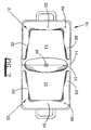
- the fluid receptacle R of the present invention is formed of a tag having first and second side 1 and 2, the bottom 3 and lower outer edges 4 of which are joined to provide a central pocket 5.
- the intermediate and upper outer edges of the first and second sides 1 and 2 are provided with cooperating sealing engagement means such as zipper elements 7 and 8 by which the remaining outer edges of the bag of receptacle R may be sealed to provide a receptacle for transporting fluid therein.
- the zipper elements 7 and 8 may also be provided across the tops of side 1 and 2 so that when engaged all edges of the receptacle R are sealed.
- the sealing engagement elements 7 and 8 are disengageable to permit the first and second sides of the bag R to be laid open on opposite sides of the central pocket 5 as shown in Fig. 2.
- the receptacle R may be laid open as in Fig. 2 and placed under the drain of a vehicle to collect oil draining therefrom. After collecting the drained oil, the receptacle R may be closed or sealed, as shown in Fig. 1, and the oil transported to a collection point or other point for disposal thereof.
- Handles 9 and 10 may be attached to the top of the first and second sides 1 and 2 for lifting and carrying the receptacle R and the contents thereof to various locations.
- FIG. 7 another preferred embodiment of the invention is shown, which, like the previous embodiment, provides a bag like receptacle R1 having first and second sides 11 and 13, the bottom 13 and lower outer edges 14 of which are joined to provide a central pocket 15.
- cooperating sealing engagement means such as zipper elements 17 and 18, are provided so that the remaining outer edges of the bag (and the top edges if desired) may be sealed, as illustrated in Fig. 3, to provide a receptacle for transporting fluid therein.
- the sealing elements 17,18 are disengageable to permit the first and second sides 11 and 12 to be laid open on opposite sides of the central pocket 15 as illustrated in Fig's 4, 5, 6, and 7.
- each of the first and second sides of the bag 11, 12 are provided with inflatable and deflatable air pockets or chambers 21 and 22.
- Each of the air pockets 21,22 are provided with an air valve 29,30 by which these pockets may be inflated or deflated.
- These valves 29 and 30 may be similar to the valves of a beach ball, allowing the pockets 21 and 22 to be inflated by the user blowing air through his mouth into the valves 29 and 30 into the corresponding air pockets 21,22.
- the cross-sectional areas of the base portion of the air pockets is relatively large.
- the cross-sectional areas of leg portions of the air pockets decrease from an area substantially the same as the base portions 23 and 24 toward the central pocket so that the surfaces of the first and second sides 11 and 12 when laid open on a horizontal surface, are inclined downwardly, as best seem in Fig's 4 and 5, from the tops thereof toward the central pocket 14.
- the central pocket 15 may be provided with a drain hole 35 which is closed when receiving and transporting fluid therein but which may be opened to allow draining of fluids from the central pocket 15.
- handles 31 and 32 may be provided for transporting the receptacle R1 and any contents therein from place to place.
- the receptacle R1 would be stored in an empty flat condition.
- Fig's 8 and 9 illustrate the receptacle R1 in an empty, deflated condition
- Fig. 8 illustrating the receptacle R1 open
- Fig. 9 the receptacle R1 closed.
- the air pockets 21 and 22 Prior to use, the air pockets 21 and 22 would be inflated by introducing air through the air valves 29 and 30.
- the sealing elements 17 and 18 would be disengaged allowing the sides of the bag 11, 12 to be laid open as shown in Fig's 4, 5, 6, and 7.
- the receptacle R1 would be placed under a vehicle with the central pocket 15 being substantially below the drain plug of the vehicle. The drain plug would be removed and fluids drained into the pocket 15.
- the receptacle R1 would be removed from under the vehicle, the receptacle would be sealingly closed by engagement of the sealing elements 17 and 18 and the receptacle R1 and its fluid contents would be carried by the handles 31 and 32 to a point of collection or other disposal.
- the drain hole 35 would be opened allowing fluids to drain therefrom. Then the drain hole would be closed and if desired, the air pockets 29 and 30 deflated. Any residual fluid would be sealed within the receptacle R1 for storage.
- the receptacle R1 would be stored in a flat position, such as Fig. 9, or folded as desired.
- a receptacle such as either the receptacle R of Fig's 1 and 2 or the receptacle R1 of Fig's 3 - 7 could be used for marinating meats or other foods.
- a whole brisket could be placed in the receptacle R sealed therein and marinated. It could be turned occasionally so that all sides would be marinated.
- the receptacle could be used for transporting, storing or disposing of other foods. It could be used for disposing of trash or contaminated substances. It could be used to collect chemical spills, to transport contaminated items, to carry laboratory samples, etc. Of course, other uses could be found for the receptacles R and R1.
- the receptacle of the present invention has many desirable characteristics. It is made in one piece so that parts of it are not lost or misplaced. Punctures can be easily repaired with a patch kit. The receptacle does not have to be cleaned prior to storage. Due to the low profile of the receptacle, a motor vehicle does not have to be elevated for a person to reach the drain plug.
Landscapes
- Engineering & Computer Science (AREA)
- General Engineering & Computer Science (AREA)
- Mechanical Engineering (AREA)
- Bag Frames (AREA)
Priority Applications (1)
| Application Number | Priority Date | Filing Date | Title |
|---|---|---|---|
| EP94303303A EP0683352A1 (fr) | 1994-05-09 | 1994-05-09 | Récipient pour fluide |
Applications Claiming Priority (1)
| Application Number | Priority Date | Filing Date | Title |
|---|---|---|---|
| EP94303303A EP0683352A1 (fr) | 1994-05-09 | 1994-05-09 | Récipient pour fluide |
Publications (1)
| Publication Number | Publication Date |
|---|---|
| EP0683352A1 true EP0683352A1 (fr) | 1995-11-22 |
Family
ID=8217696
Family Applications (1)
| Application Number | Title | Priority Date | Filing Date |
|---|---|---|---|
| EP94303303A Withdrawn EP0683352A1 (fr) | 1994-05-09 | 1994-05-09 | Récipient pour fluide |
Country Status (1)
| Country | Link |
|---|---|
| EP (1) | EP0683352A1 (fr) |
Citations (3)
| Publication number | Priority date | Publication date | Assignee | Title |
|---|---|---|---|---|
| BE562747A (fr) * | 1900-01-01 | |||
| US4732273A (en) * | 1987-06-02 | 1988-03-22 | Demarco Daniel J | Protective container for caramel apples |
| WO1991017919A1 (fr) * | 1990-05-14 | 1991-11-28 | Icsc Ltd. | Systeme de recuperation de deversements dans la terre |
-
1994
- 1994-05-09 EP EP94303303A patent/EP0683352A1/fr not_active Withdrawn
Patent Citations (3)
| Publication number | Priority date | Publication date | Assignee | Title |
|---|---|---|---|---|
| BE562747A (fr) * | 1900-01-01 | |||
| US4732273A (en) * | 1987-06-02 | 1988-03-22 | Demarco Daniel J | Protective container for caramel apples |
| WO1991017919A1 (fr) * | 1990-05-14 | 1991-11-28 | Icsc Ltd. | Systeme de recuperation de deversements dans la terre |
Similar Documents
| Publication | Publication Date | Title |
|---|---|---|
| US5316386A (en) | Fluid receptacle | |
| US4533042A (en) | Motor oil change kit and catch pan for use in changing automotive motor oil | |
| US5285824A (en) | Vehicle oil drainage apparatus and method | |
| US4403692A (en) | Motor oil change kit | |
| US7225841B2 (en) | Collapsible container for containing liquid, such as spent motor oil, and method of using same | |
| US4301841A (en) | Multipurpose container | |
| US4823947A (en) | Device for packaging, storing and disposing of oil and other products | |
| US4969571A (en) | Container for fluids | |
| US5425456A (en) | Waste collection and separation apparatus and method | |
| US4022257A (en) | Funnel-drainer device | |
| CA1316123C (fr) | Recipient collecteur de fluide | |
| US20020023929A1 (en) | Synthetic resin liquid container | |
| US5503246A (en) | Crankcase oil drain pan | |
| WO1992006901A1 (fr) | Conteneur pour dechets solides | |
| AU2002300193B2 (en) | Waste recycling bin | |
| US4512463A (en) | Free-standing flexible container for fluids | |
| US20240077173A1 (en) | Collapsible fluid collection container | |
| US5489042A (en) | Reusable waste handler for vehicular oil changes | |
| US4557395A (en) | Portable container with interlocking funnel | |
| US6880589B2 (en) | Container for collecting and transporting drained oil | |
| US20080121582A1 (en) | Filter recycling unit | |
| US5421381A (en) | Reusable used oil filter and oil recycling container | |
| US6068032A (en) | Container and system for collection and recycling used motor oil | |
| USRE32458E (en) | Portable container with interlocking funnel | |
| EP0683352A1 (fr) | Récipient pour fluide |
Legal Events
| Date | Code | Title | Description |
|---|---|---|---|
| PUAI | Public reference made under article 153(3) epc to a published international application that has entered the european phase |
Free format text: ORIGINAL CODE: 0009012 |
|
| AK | Designated contracting states |
Kind code of ref document: A1 Designated state(s): DE ES FR GB IT |
|
| RAX | Requested extension states of the european patent have changed |
Free format text: SI |
|
| 17P | Request for examination filed |
Effective date: 19960430 |
|
| 17Q | First examination report despatched |
Effective date: 19980323 |
|
| GRAG | Despatch of communication of intention to grant |
Free format text: ORIGINAL CODE: EPIDOS AGRA |
|
| GRAG | Despatch of communication of intention to grant |
Free format text: ORIGINAL CODE: EPIDOS AGRA |
|
| GRAH | Despatch of communication of intention to grant a patent |
Free format text: ORIGINAL CODE: EPIDOS IGRA |
|
| GRAH | Despatch of communication of intention to grant a patent |
Free format text: ORIGINAL CODE: EPIDOS IGRA |
|
| STAA | Information on the status of an ep patent application or granted ep patent |
Free format text: STATUS: THE APPLICATION IS DEEMED TO BE WITHDRAWN |
|
| 18D | Application deemed to be withdrawn |
Effective date: 20001201 |