EP0683355A1 - Kraftfahrzeugleuchte - Google Patents
Kraftfahrzeugleuchte Download PDFInfo
- Publication number
- EP0683355A1 EP0683355A1 EP95107503A EP95107503A EP0683355A1 EP 0683355 A1 EP0683355 A1 EP 0683355A1 EP 95107503 A EP95107503 A EP 95107503A EP 95107503 A EP95107503 A EP 95107503A EP 0683355 A1 EP0683355 A1 EP 0683355A1
- Authority
- EP
- European Patent Office
- Prior art keywords
- prism
- reflector
- lens
- luminaire according
- lamp
- Prior art date
- Legal status (The legal status is an assumption and is not a legal conclusion. Google has not performed a legal analysis and makes no representation as to the accuracy of the status listed.)
- Granted
Links
Images
Classifications
-
- F—MECHANICAL ENGINEERING; LIGHTING; HEATING; WEAPONS; BLASTING
- F21—LIGHTING
- F21V—FUNCTIONAL FEATURES OR DETAILS OF LIGHTING DEVICES OR SYSTEMS THEREOF; STRUCTURAL COMBINATIONS OF LIGHTING DEVICES WITH OTHER ARTICLES, NOT OTHERWISE PROVIDED FOR
- F21V7/00—Reflectors for light sources
- F21V7/0025—Combination of two or more reflectors for a single light source
-
- F—MECHANICAL ENGINEERING; LIGHTING; HEATING; WEAPONS; BLASTING
- F21—LIGHTING
- F21S—NON-PORTABLE LIGHTING DEVICES; SYSTEMS THEREOF; VEHICLE LIGHTING DEVICES SPECIALLY ADAPTED FOR VEHICLE EXTERIORS
- F21S43/00—Signalling devices specially adapted for vehicle exteriors, e.g. brake lamps, direction indicator lights or reversing lights
- F21S43/10—Signalling devices specially adapted for vehicle exteriors, e.g. brake lamps, direction indicator lights or reversing lights characterised by the light source
- F21S43/13—Signalling devices specially adapted for vehicle exteriors, e.g. brake lamps, direction indicator lights or reversing lights characterised by the light source characterised by the type of light source
- F21S43/14—Light emitting diodes [LED]
-
- B—PERFORMING OPERATIONS; TRANSPORTING
- B60—VEHICLES IN GENERAL
- B60K—ARRANGEMENT OR MOUNTING OF PROPULSION UNITS OR OF TRANSMISSIONS IN VEHICLES; ARRANGEMENT OR MOUNTING OF PLURAL DIVERSE PRIME-MOVERS IN VEHICLES; AUXILIARY DRIVES FOR VEHICLES; INSTRUMENTATION OR DASHBOARDS FOR VEHICLES; ARRANGEMENTS IN CONNECTION WITH COOLING, AIR INTAKE, GAS EXHAUST OR FUEL SUPPLY OF PROPULSION UNITS IN VEHICLES
- B60K35/00—Instruments specially adapted for vehicles; Arrangement of instruments in or on vehicles
- B60K35/20—Output arrangements, i.e. from vehicle to user, associated with vehicle functions or specially adapted therefor
-
- B—PERFORMING OPERATIONS; TRANSPORTING
- B60—VEHICLES IN GENERAL
- B60K—ARRANGEMENT OR MOUNTING OF PROPULSION UNITS OR OF TRANSMISSIONS IN VEHICLES; ARRANGEMENT OR MOUNTING OF PLURAL DIVERSE PRIME-MOVERS IN VEHICLES; AUXILIARY DRIVES FOR VEHICLES; INSTRUMENTATION OR DASHBOARDS FOR VEHICLES; ARRANGEMENTS IN CONNECTION WITH COOLING, AIR INTAKE, GAS EXHAUST OR FUEL SUPPLY OF PROPULSION UNITS IN VEHICLES
- B60K35/00—Instruments specially adapted for vehicles; Arrangement of instruments in or on vehicles
- B60K35/60—Instruments characterised by their location or relative disposition in or on vehicles
-
- F—MECHANICAL ENGINEERING; LIGHTING; HEATING; WEAPONS; BLASTING
- F21—LIGHTING
- F21S—NON-PORTABLE LIGHTING DEVICES; SYSTEMS THEREOF; VEHICLE LIGHTING DEVICES SPECIALLY ADAPTED FOR VEHICLE EXTERIORS
- F21S41/00—Illuminating devices specially adapted for vehicle exteriors, e.g. headlamps
- F21S41/10—Illuminating devices specially adapted for vehicle exteriors, e.g. headlamps characterised by the light source
- F21S41/14—Illuminating devices specially adapted for vehicle exteriors, e.g. headlamps characterised by the light source characterised by the type of light source
- F21S41/17—Discharge light sources
- F21S41/173—Fluorescent light sources
-
- F—MECHANICAL ENGINEERING; LIGHTING; HEATING; WEAPONS; BLASTING
- F21—LIGHTING
- F21S—NON-PORTABLE LIGHTING DEVICES; SYSTEMS THEREOF; VEHICLE LIGHTING DEVICES SPECIALLY ADAPTED FOR VEHICLE EXTERIORS
- F21S43/00—Signalling devices specially adapted for vehicle exteriors, e.g. brake lamps, direction indicator lights or reversing lights
- F21S43/30—Signalling devices specially adapted for vehicle exteriors, e.g. brake lamps, direction indicator lights or reversing lights characterised by reflectors
-
- F—MECHANICAL ENGINEERING; LIGHTING; HEATING; WEAPONS; BLASTING
- F21—LIGHTING
- F21S—NON-PORTABLE LIGHTING DEVICES; SYSTEMS THEREOF; VEHICLE LIGHTING DEVICES SPECIALLY ADAPTED FOR VEHICLE EXTERIORS
- F21S43/00—Signalling devices specially adapted for vehicle exteriors, e.g. brake lamps, direction indicator lights or reversing lights
- F21S43/30—Signalling devices specially adapted for vehicle exteriors, e.g. brake lamps, direction indicator lights or reversing lights characterised by reflectors
- F21S43/31—Optical layout thereof
-
- B—PERFORMING OPERATIONS; TRANSPORTING
- B60—VEHICLES IN GENERAL
- B60K—ARRANGEMENT OR MOUNTING OF PROPULSION UNITS OR OF TRANSMISSIONS IN VEHICLES; ARRANGEMENT OR MOUNTING OF PLURAL DIVERSE PRIME-MOVERS IN VEHICLES; AUXILIARY DRIVES FOR VEHICLES; INSTRUMENTATION OR DASHBOARDS FOR VEHICLES; ARRANGEMENTS IN CONNECTION WITH COOLING, AIR INTAKE, GAS EXHAUST OR FUEL SUPPLY OF PROPULSION UNITS IN VEHICLES
- B60K2360/00—Indexing scheme associated with groups B60K35/00 or B60K37/00 relating to details of instruments or dashboards
- B60K2360/20—Optical features of instruments
- B60K2360/33—Illumination features
-
- F—MECHANICAL ENGINEERING; LIGHTING; HEATING; WEAPONS; BLASTING
- F21—LIGHTING
- F21S—NON-PORTABLE LIGHTING DEVICES; SYSTEMS THEREOF; VEHICLE LIGHTING DEVICES SPECIALLY ADAPTED FOR VEHICLE EXTERIORS
- F21S43/00—Signalling devices specially adapted for vehicle exteriors, e.g. brake lamps, direction indicator lights or reversing lights
- F21S43/10—Signalling devices specially adapted for vehicle exteriors, e.g. brake lamps, direction indicator lights or reversing lights characterised by the light source
- F21S43/13—Signalling devices specially adapted for vehicle exteriors, e.g. brake lamps, direction indicator lights or reversing lights characterised by the light source characterised by the type of light source
-
- F—MECHANICAL ENGINEERING; LIGHTING; HEATING; WEAPONS; BLASTING
- F21—LIGHTING
- F21V—FUNCTIONAL FEATURES OR DETAILS OF LIGHTING DEVICES OR SYSTEMS THEREOF; STRUCTURAL COMBINATIONS OF LIGHTING DEVICES WITH OTHER ARTICLES, NOT OTHERWISE PROVIDED FOR
- F21V7/00—Reflectors for light sources
- F21V7/0008—Reflectors for light sources providing for indirect lighting
- F21V7/0016—Reflectors for light sources providing for indirect lighting on lighting devices that also provide for direct lighting, e.g. by means of independent light sources, by splitting of the light beam, by switching between both lighting modes
-
- F—MECHANICAL ENGINEERING; LIGHTING; HEATING; WEAPONS; BLASTING
- F21—LIGHTING
- F21Y—INDEXING SCHEME ASSOCIATED WITH SUBCLASSES F21K, F21L, F21S and F21V, RELATING TO THE FORM OR THE KIND OF THE LIGHT SOURCES OR OF THE COLOUR OF THE LIGHT EMITTED
- F21Y2103/00—Elongate light sources, e.g. fluorescent tubes
- F21Y2103/30—Elongate light sources, e.g. fluorescent tubes curved
- F21Y2103/37—U-shaped
Definitions
- the invention relates to a motor vehicle lamp according to the preamble of claim 1.
- the invention has for its object to design the generic motor vehicle lamp so that the lens is evenly illuminated with a simple design of the lamp.
- a part of the reflected light rays falls on the prism, which reflects the light rays to the reflector, through which the light rays are directed to the lens.
- the interposition of the prism ensures excellent uniform illumination of the lens with a simple structural design.
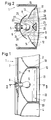
- the motor vehicle lamp is a rear lamp with a housing 1, in which lamp chambers 2 to 4 are provided next to one another.
- Each lamp chamber has an incandescent lamp 5, of which only one incandescent lamp is shown in FIGS. 1 and 2.
- the incandescent lamp 5 is seated in a known manner in a socket 6 which is arranged on the rear wall 7 of the housing 1.
- the incandescent lamps 5 provided in the other lamp chambers are held in the same way.
- the incandescent lamp 5 of the lamp chamber 3 is partially surrounded by a reflector 8, on which the rays emitted by the incandescent lamp 5 are reflected.
- the reflector 8 can be elliptical, parabolic or the like in cross-section or can also have free shaped surfaces.
- part 9 of the light beams is reflected by the reflector 8 to form a lens 10, which closes the housing 1 at the rear.
- additional reflectors 11 and 12 FIG. 2
- the additional reflectors 11, 12 can also have a correspondingly curved cross-sectional shape. As shown in FIG.
- the additional reflectors 11, 12 extend from the upper and lower edge of the lens 10 into the luminaire chamber 3.
- the additional reflectors 11, 12 adjoin side walls 15, 16 with which they are advantageously formed in one piece.
- the additional reflectors 11, 12 are fastened to the lamp housing 1, preferably at the edge thereof, via the side walls 15, 16.
- the additional reflectors 11, 12 extend so far into the lamp chamber 3 (Fig. 2) that they, in view seen the lens 10, slightly overlap the reflector 8.
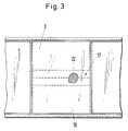
- the prism 17 In the area between the incandescent lamp 5 and the lens 10 there is a prism 17 at the level of the incandescent lamp, which extends over the entire length of the lamp chamber 3 and adjoins side walls 18, 19 of the lamp chamber 3 (FIG. 1).
- the prism 17 runs at a short distance from the lens 10 within the lamp chamber 3 and is preferably made of a suitable plastic.
- the prism 17 can also be formed in one piece with the lens 10.
- the flat prism side 20 facing the lens 10 can be provided with a reflector optic 21. It consists of individual small prisms 22, which preferably have a triple shape.
- Such a design of the prism 17 has the advantage that a separate surface is not required for a reflector, but that the prism side 20 can be used for this.
- the other two sides 23 and 24 of the prism 17, which is triangular in cross section, are provided with mirror surfaces 25 and 26, which ensure that the light rays striking the prism 17 are divided into at least two light rays.
- a part 27 of the rays emitted by the incandescent lamp 5 strikes the mirror surfaces 25, 26 of the prism 17 after reflection on the reflector 8. From there, these partial rays are reflected to the additional reflectors 11, 12, these light rays in two partial beams 28 and 29 are split. Both partial beams 28, 29 reach the additional reflectors 11, 12, which then reflect these partial beams in the direction of the lens 10.
- the reflector 8, the prism 17 and the additional reflectors 11, 12 are designed such that all partial beams 9, 28, 29 pass through the lens 10 in parallel to one another.
- the lens 10 is evenly illuminated over its height and width, with a part 9 of the rays emitted by the incandescent lamp 5 being directed directly to the lens 10 by the reflector 8 and another part 27 to 29 from the reflector 8 via the prism 17 and the additional reflectors 11 , 12 is reflected to the lens 10.
- the prism 17 is preferably accommodated in the lamp chamber 3 in which a red signal color of the lamp is generated.
- the prism 17 can also extend over the entire length of the lamp.
- the side 20 of the prism 17 facing the lens 10 is formed in a color-neutral manner outside the area of the lamp assigned to the red light. In these areas, however, the prism side 20 can also be kept, for example, in the color of the paintwork of the motor vehicle. Since the reflector optics 21 are no longer provided on the lens 10 but on the prism 17, the luminaire has a uniform appearance.
- the areas of the lens 10 assigned to the individual signal lamps can have the corresponding color tint, so that the lens has a color division.
- lens 10 it is also possible to uniformly color the lens 10 as a whole and to switch on a filter in the beam path within the lamp, which generates the corresponding signal color of the lens when the respective incandescent lamp 5 is actuated. In any case, corresponding light optics are not visible on the lens 10.
- incandescent lamp 5 instead of the incandescent lamp 5, it is of course also possible to use any other suitable lamp body, such as a neon tube or an LED.
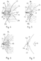
- an LED 5a is used as the lamp body, which is arranged on the side of the reflector 8a facing away from the lens (not shown).
- the reflector 8a can be elliptical, parabolic or the like in cross section or have free shaped surfaces.
- the reflector 8a has an opening 30 in which a light-refractive optic 31 is arranged. The light emitted by the LED 5a strikes the light-refracting optics 31, through which the diverging beams 32 are broken up into parallel beams 32 '. They meet the prism sides 23 and 24 of the prism 17, which is provided on the side of the reflector 8a facing the lens at a distance from the optics 31.
- the dimensions of the prism 17 are matched to the dimensions of the optics 31 such that all the rays 32 ′ passing through the optics 31 strike the prism sides 23 and 24.
- the prism sides are provided with the mirror surfaces 25 and 26, which are designed in such a way that the parallel rays 32 'are reflected to the reflector 8a.
- the rays to the (not shown) lens of the lamp are reflected on it.
- the arrangement is such that the reflector 8a rays reflected to the lens run parallel to one another.
- the prism 17 is arranged symmetrically with respect to the optics 31 in such a way that the same number of beams 32 ′ strike the two prism sides 23, 24.
- the mirror surfaces 25, 26 of the prism sides 23, 24 can also be designed in accordance with the previous exemplary embodiment in such a way that the light beams 32 'incident on the prism 17 are divided into at least two light beams and reflected to the reflector 8a. Otherwise, the prism 17 can be designed in accordance with the previous embodiment.
- the prism 17 optimally illuminates the lens in a simple manner.
- the lamp can have several reflectors 8a for the light distribution.
- the light window itself does not require lenses, deflection elements and the like, so that it can be simple.
- the LED 5a is located behind the prism 17 in the radiation direction, so that the lamp body is not visible from the outside.
- an LED 5b is again used as the lamp body, the rays 32 of which run through the opening 30 of the reflector 8b.
- the rays 32 diverging from the LED 5b therefore partially hit the prism 17 after passing through the opening 30, on the prism surfaces 23 and 24 of which the rays are reflected to the reflector 8b.
- the rays are reflected on it in such a way that they pass through the lens (not shown) in parallel to one another.
- the Prism sides 23, 24 are provided with corresponding mirror surfaces 25 and 26.
- the prism 17 can otherwise be of the same design as in the embodiment according to FIGS. 1 to 3.
- FIG. 6 differs from the embodiment of FIG. 5 only in that a rod-shaped neon tube is used as the lamp body 5c.
- the rays 32 emitted by it pass through the opening 30 of the reflector 8c and partially strike the prism 17.
- the rest of the rays 32 reach the lens (not shown) of the lamp directly.
- the neon tube 5c is surrounded by a reflector 33 which projects from the opening 30 of the reflector 8c over its side facing away from the prism 17.
- This reflector 33 can be cylindrical, parabolic and the like in cross section. This additional reflector 33 ensures that the light emitted by the neon tube 5c is completely reflected by the opening 30 of the reflector 8c.
- Fig. 7 shows an embodiment in which the lamp body 5d is a U-shaped neon tube. It has the two legs 34 and 35, which are connected by a curved connector 36 merge. The legs 34, 35 of the neon tube 5d extend parallel to the longitudinal axis of the prism 17. The neon tube 5d is accommodated in the additional reflector 33, which is of the same design as in the previous exemplary embodiment.
- the rays emitted by the neon tube 5d are not shown in FIG. 7.
- the beam path corresponds to the representation in FIG. 6.
- the exemplary embodiment according to FIG. 7 has the same design as the exemplary embodiment according to FIG. 6.
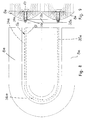
- the motor vehicle lamp which in turn has a U-shaped neon tube 5e as the lamp body. It has the two legs 34e, 35e lying parallel to one another, which merge into one another through the bent connecting piece 36e.
- the neon tube 5e is surrounded by the additional reflector 33e, which is U-shaped in accordance with the neon tube 5e. It surrounds the neon tube 5e over its entire length.
- the additional reflector 33e can in turn be partially cylindrical, parabolic or the like.
- the prism 17 also has a corresponding U-shaped course (FIG. 8), so that it lies in front of the neon tube 5e over the entire length in the beam direction.
- the reflector 8e also has a U-shaped course. As shown in FIGS. 8 and 9, the mutually facing edges of the reflector 8e lie linearly against one another. Otherwise, the reflector 8e has the same cross section as in the previous exemplary embodiments.
- the opening 30e through which the rays emitted by the neon tube 5e pass, also extends in a U-shape.
- the light emitted over the length of the neon tube 5e passes through this U-shaped opening 30e through the reflector 8e and partially strikes the U-shaped prism.
- the rest of the light rays go directly to the lens (not shown) of the lamp.
- the beam path is the same as in the exemplary embodiment according to FIG. 6.
- the neon tube and thus also the prism 17 can also have a different shape instead of a U-shaped configuration, for example annular, W-shaped, S-shaped, spiral or wave-shaped design.
- the mutually facing edges of the U-shaped reflector 8e can also be spaced apart.
- LEDs and neon tubes come into consideration as luminaire bodies, but also, for example, from light guides.
Landscapes
- Engineering & Computer Science (AREA)
- General Engineering & Computer Science (AREA)
- Chemical & Material Sciences (AREA)
- Combustion & Propulsion (AREA)
- Transportation (AREA)
- Mechanical Engineering (AREA)
- Physics & Mathematics (AREA)
- Microelectronics & Electronic Packaging (AREA)
- Optics & Photonics (AREA)
- Non-Portable Lighting Devices Or Systems Thereof (AREA)
- Lighting Device Outwards From Vehicle And Optical Signal (AREA)
Abstract
Description
- Die Erfindung betrifft eine Kraftfahrzeugleuchte nach dem Oberbegriff des Anspruches 1.
- Bei bekannten Kraftfahrzeugleuchten wird das von einer Glühlampe ausgesandte Licht auf einen Reflektor geworfen, der die Lichtstrahlen zur Lichtscheibe reflektiert. Um eine gleichmäßige Ausleuchtung der Lichtscheibe zu erreichen, ist eine aufwendige Gestaltung des Reflektors notwendig.
- Der Erfindung liegt die Aufgabe zugrunde, die gattungsgemäße Kraftfahrzeugleuchte so auszubilden, daß bei einfacher Gestaltung der Leuchte die Lichtscheibe gleichmäßig ausgeleuchtet wird.
- Diese Aufgabe wird bei der gattungsgemäßen Kraftfahrzeugleuchte erfindungsgemäß mit den kennzeichnenden Merkmalen des Anspruches 1 gelöst.
- Bei der erfindungsgemäßen Kraftfahrzeugleuchte fällt ein Teil der reflektierten Lichtstrahlen auf das Prisma, das die Lichtstrahlen zum Reflektor reflektiert, durch welchen die Lichtstrahlen zur Lichtscheibe gelenkt werden. Durch die Zwischenschaltung des Prismas wird bei einfacher konstruktiver Gestaltung eine hervorragende gleichmäßige Ausleuchtung der Lichtscheibe gewährleistet.
- Weitere Merkmale der Erfindung ergeben sich aus den weiteren Ansprüchen, der Beschreibung und den Zeichnungen.
- Die Erfindung wird anhand eines in den Zeichnungen dargestellten Ausführungsbeispieles näher erläutert. Es zeigen
- Fig. 1
- in einem Längsschnitt einen Teil einer erfindungsgemäßen Kraftfahrzeugleuchte,
- Fig. 2
- einen Schnitt längs der Linie II-II in Fig. 1,
- Fig. 3
- in Ansicht die Kraftfahrzeugleuchte gemäß Fig. 1,
- Fig. 4 bis Fig. 7
- jeweils in Darstellungen entsprechend Fig. 2 weitere Ausführungsformen von erfindungsgemäßen Kraftfahrzeugleuchten,
- Fig. 8
- eine Draufsicht auf einen Teil einer weiteren Ausführungsform einer erfindungsgemäßen Kraftfahrzeugleuchte,
- Fig. 9
- im Längsschnitt die Kraftfahrzeugleuchte gemäß Fig. 8.
- Die Kraftfahrzeugleuchte ist im Ausführungsbeispiel eine Heckleuchte mit einem Gehäuse 1, in dem nebeneinander Leuchtenkammern 2 bis 4 vorgesehen sind. Jede Leuchtenkammer hat eine Glühlampe 5, von denen in den Fig. 1 und 2 nur eine Glühlampe dargestellt ist. Die Glühlampe 5 sitzt in bekannter Weise in einer Fassung 6, die an der Rückwand 7 des Gehäuses 1 angeordnet ist. Die in den übrigen Leuchtenkammern vorgesehenen Glühlampen 5 sind in gleicher Weise gehalten.
- Die Glühlampe 5 der Leuchtenkammer 3 wird von einem Reflektor 8 teilweise umgeben, an dem die von der Glühlampe 5 ausgesandten Strahlen reflektiert werden. Der Reflektor 8 kann im Querschnitt elliptisch, parabelförmig oder dergleichen ausgebildet sein oder auch freie Formflächen haben. Wie Fig. 2 zeigt, wird ein Teil 9 der Lichtstrahlen vom Reflektor 8 zu einer Lichtscheibe 10 reflektiert, die das Gehäuse 1 an der Rückseite verschließt. Im Bereich zwischen der Lichtscheibe 10 und dem Reflektor 8 befinden sich zwei Zusatzreflektoren 11 und 12 (Fig. 2), die aus ebenen Spiegelflächen 13, 14 zusammengesetzt sein können. Die Zusatzreflektoren 11, 12 können aber auch eine entsprechend gekrümmte Querschnittsform haben. Wie Fig. 2 zeigt, erstrecken sich die Zusatzreflektoren 11, 12 vom oberen und unteren Rand der Lichtscheibe 10 aus in die Leuchtenkammer 3. Die Zusatzreflektoren 11, 12 schließen an Seitenwände 15, 16 an, mit denen sie vorteilhaft einstückig ausgebildet sind. Über die Seitenwände 15, 16 sind die Zusatzreflektoren 11, 12 am Leuchtengehäuse 1, vorzugsweise an dessen Rand, befestigt.
- Die Zusatzreflektoren 11, 12 erstrecken sich so weit in die Leuchtenkammer 3 (Fig. 2), daß sie, in Ansicht auf die Lichtscheibe 10 gesehen, den Reflektor 8 geringfügig überlappen.
- Im Bereich zwischen der Glühlampe 5 und der Lichtscheibe 10 befindet sich in Höhe der Glühlampe ein Prisma 17, das sich über die gesamte Länge der Leuchtenkammer 3 erstreckt und an Seitenwände 18, 19 der Leuchtenkammer 3 anschließt (Fig. 1). Das Prisma 17 verläuft mit geringem Abstand von der Lichtscheibe 10 innerhalb der Leuchtenkammer 3 und besteht vorzugsweise aus geeignetem Kunststoff. Abweichend vom dargestellten Ausführungsbeispiel kann das Prisma 17 auch einstückig mit der Lichtscheibe 10 ausgebildet sein. Die der Lichtscheibe 10 zugewandte ebene Prismenseite 20 kann mit einer Rückstrahleroptik 21 versehen sein. Sie besteht aus einzelnen kleinen Prismen 22, die vorzugsweise Tripelform haben. Eine solche Ausbildung des Prismas 17 hat den Vorteil, daß für einen Rückstrahler eine gesonderte Fläche nicht erforderlich ist, sondern daß die Prismenseite 20 hierfür verwendet werden kann.
- Die beiden anderen Seiten 23 und 24 des im Querschnitt dreieckigen Prismas 17 sind mit Spiegelflächen 25 und 26 versehen, die dafür sorgen, daß die auf das Prisma 17 auffallenden Lichtstrahlen in wenigstens zwei Lichtstrahlen aufgeteilt werden. Wie Fig. 2 zeigt, trifft ein Teil 27 der von der Glühlampe 5 ausgesandten Strahlen nach der Reflexion am Reflektor 8 auf die Spiegelflächen 25, 26 des Prismas 17. Von dort werden diese Teilstrahlen zu den Zusatzreflektoren 11, 12 reflektiert, wobei diese Lichtstrahlen in zwei Teilstrahlen 28 und 29 aufgespalten werden. Beide Teilstrahlen 28, 29 gelangen auf die Zusatzreflektoren 11, 12, welche diese Teilstrahlen dann in Richtung auf die Lichtscheibe 10 reflektieren.
- Der Reflektor 8, das Prisma 17 und die Zusatzreflektoren 11, 12 sind so ausgebildet, daß sämtliche Teilstrahlen 9, 28, 29 parallel zueinander durch die Lichtscheibe 10 hindurchtreten. Somit wird die Lichtscheibe 10 über ihre Höhe und Breite gleichmäßig ausgeleuchtet, wobei ein Teil 9 der von der Glühlampe 5 ausgesandten Strahlen durch den Reflektor 8 unmittelbar zur Lichtscheibe 10 und ein anderer Teil 27 bis 29 vom Reflektor 8 über das Prisma 17 und die Zusatzreflektoren 11, 12 zur Lichtscheibe 10 reflektiert wird.
- Es ist möglich, die Spiegelflächen 25, 26 an den Prismenseiten 23, 24 so auszubilden, daß der Teil 27 der Lichtstrahlen an den Spiegelflächen 25, 26 nicht aufgespalten, sondern lediglich zu den Zusatzreflektoren 11, 12 reflektiert wird.
- Das Prisma 17 ist bevorzugt in derjenigen Leuchtenkammer 3 untergebracht, in der eine rote Signalfarbe der Leuchte erzeugt wird. Das Prisma 17 kann sich aber auch über die gesamte Länge der Leuchte erstrecken. In diesem Falle ist die der Lichtscheibe 10 zugewandte Seite 20 des Prismas 17 außerhalb des dem Rotlicht zugeordneten Bereiches der Leuchte farbneutral ausgebildet. In diesen Bereichen kann die Prismenseite 20 aber auch beispielsweise im Farbton der Lackierung des Kraftfahrzeuges gehalten werden. Da die Rückstrahleroptik 21 nicht mehr an der Lichtscheibe 10, sondern am Prisma 17 vorgesehen ist, bietet die Leuchte ein einheitliches Erscheinungsbild. Die den einzelnen Signalleuchten zugeordneten Bereiche der Lichtscheibe 10 können die entsprechende Farbtönung aufweisen, so daß die Lichtscheibe eine farbliche Unterteilung aufweist. Es ist aber auch möglich, die Lichtscheibe 10 insgesamt einheitlich einzufärben und in den Strahlengang innerhalb der Leuchte ein Filter einzuschalten, das bei Betätigen der jeweiligen Glühlampe 5 die entsprechende Signalfarbe der Lichtscheibe erzeugt. Auf jeden Fall ist auf der Lichtscheibe 10 eine entsprechende Lichtoptik nicht sichtbar.
- Anstelle der Glühlampe 5 kann selbstverständlich auch jeder andere geeignete Leuchtenkörper, wie eine Neonröhre oder eine LED eingesetzt werden.
- Beim Ausführungsbeispiel nach Fig. 4 wird als Leuchtenkörper eine LED 5a verwendet, die auf der von der (nicht dargestellten) Lichtscheibe abgewandten Seite des Reflektors 8a angeordnet ist. Wie beim vorigen Ausführungsbeispiel kann der Reflektor 8a im Querschnitt elliptisch, parabelförmig oder dergleichen ausgebildet sein oder freie Formflächen haben. Der Reflektor 8a hat eine Öffnung 30, in der eine Licht brechende Optik 31 angeordnet ist. Das von der LED 5a ausgesandte Licht trifft auf die Licht brechende Optik 31, durch welche die divergierenden Strahlen 32 in parallele Strahlen 32' gebrochen werden. Sie treffen auf die Prismenseiten 23 und 24 des Prismas 17, das auf der der Lichtscheibe zugewandten Seite des Reflektors 8a mit Abstand zur Optik 31 vorgesehen ist. Die Abmessungen des Prismas 17 sind so auf die Abmessungen der Optik 31 abgestimmt, daß sämtliche durch die Optik 31 hindurchtretende Strahlen 32' auf die Prismenseiten 23 und 24 treffen. Die Prismenseiten sind wie beim vorigen Ausführungsbeispiel mit den Spiegelflächen 25 und 26 versehen, die so ausgebildet sind, daß die parallelen Strahlen 32' zum Reflektor 8a reflektiert werden. An ihm werden die Strahlen zur (nicht dargestellten) Lichtscheibe der Leuchte reflektiert. Die Anordnung ist so getroffen, daß die vom Reflektor 8a zur Lichtscheibe reflektierten Strahlen parallel zueinander verlaufen. Das Prisma 17 ist in bezug auf die Optik 31 derart symmetrisch angeordnet, daß auf die beiden Prismenseiten 23, 24 gleich viele Strahlen 32' treffen.
- Die Spiegelflächen 25, 26 der Prismenseiten 23, 24 können entsprechend dem vorigen Ausführungsbeispiel auch so gestaltet sein, daß die auf das Prisma 17 auffallenden Lichtstrahlen 32' in wenigstens zwei Lichtstrahlen aufgeteilt und zum Reflektor 8a reflektiert werden. Im übrigen kann das Prisma 17 entsprechend der vorigen Ausführungsform ausgebildet sein. Mit dem Prisma 17 wird eine optimale Ausleuchtung der Lichtscheibe in einfacher Weise erreicht.
- Die Leuchte kann mehrere Reflektoren 8a für die Lichtverteilung aufweisen. Das Lichtfenster selbst benötigt keine Linsen, Umlenkelemente und dergleichen, so daß es einfach ausgebildet sein kann. Die LED 5a befindet sich in Strahlungsrichtung hinter dem Prisma 17, so daß der Leuchtenkörper von außen nicht sichtbar ist.
- Beim Ausführungsbeispiel nach Fig. 5 wird als Leuchtenkörper wiederum eine LED 5b verwendet, deren Strahlen 32 durch die Öffnung 30 des Reflektors 8b verlaufen. Im Gegensatz zum vorigen Ausführungsbeispiel ist eine Licht brechende Optik nicht vorhanden. Die von der LED 5b aus divergierenden Strahlen 32 treffen darum nach dem Durchtritt durch die Öffnung 30 teilweise auf das Prisma 17, an dessen Prismenflächen 23 und 24 die Strahlen zum Reflektor 8b reflektiert werden. An ihm werden die Strahlen wiederum so reflektiert, daß sie parallel zueinander durch die (nicht dargestellte) Lichtscheibe treten. Die Prismenseiten 23, 24 sind mit entsprechenden Spiegelflächen 25 und 26 versehen.
- Da die Strahlen 32 von der LED 5b aus divergierend verlaufen, trifft ein Teil der Strahlen 32 nicht auf das Prisma 17, sondern gelangt ohne Reflexion direkt zur Lichtscheibe.
- Auch mit dieser Ausführungsform wird eine optimale Ausleuchtung der Lichtscheibe über deren Höhe und Breite erreicht. Das Prisma 17 kann im übrigen gleich ausgebildet sein wie beim Ausführungsbeispiel nach den Fig. 1 bis 3.
- Die Ausführungsform nach Fig. 6 unterscheidet sich vom Ausführungsbeispiel nach Fig. 5 lediglich dadurch, daß als Leuchtenkörper 5c eine stabförmige Neonröhre verwendet wird. Die von ihr ausgesandten Strahlen 32 treten durch die Öffnung 30 des Reflektors 8c hindurch und treffen teilweise auf das Prisma 17. Der übrige Teil der Strahlen 32 gelangt unmittelbar zur (nicht dargestellten) Lichtscheibe der Leuchte. Die Neonröhre 5c wird von einem Reflektor 33 umgeben, der von der Öffnung 30 des Reflektors 8c aus über dessen vom Prisma 17 abgewandte Seite ragt. Dieser Reflektor 33 kann im Querschnitt zylindrisch, parabelförmig und dergleichen ausgebildet sein. Durch diesen zusätzlichen Reflektor 33 ist gewährleistet, daß das von der Neonröhre 5c ausgesandte Licht vollständig durch die Öffnung 30 des Reflektors 8c reflektiert wird.
- Fig. 7 zeigt eine Ausführungsform, bei der der Leuchtenkörper 5d eine U-förmige Neonröhre ist. Sie hat die beiden Schenkel 34 und 35, die durch ein gebogenes Verbindungsstück 36 ineinander übergehen. Die Schenkel 34, 35 der Neonröhre 5d erstrecken sich parallel zur Längsachse des Prismas 17. Die Neonröhre 5d ist im Zusatzreflektor 33 untergebracht, der gleich ausgebildet ist wie beim vorigen Ausführungsbeispiel.
- Der Übersichtlichkeit wegen sind in Fig. 7 die von der Neonröhre 5d ausgesandten Strahlen nicht dargestellt. Der Strahlenverlauf entspricht der Darstellung in Fig. 6. Im übrigen ist das Ausführungsbeispiel nach Fig. 7 gleich ausgebildet wie das Ausführungsbeispiel nach Fig. 6.
- Die Fig. 8 und 9 zeigen einen Teil einer Kraftfahrzeugleuchte, die als Leuchtenkörper wiederum eine U-förmige Neonröhre 5e aufweist. Sie hat die beiden parallel zueinander liegenden Schenkel 34e, 35e, die durch das gebogene Verbindungsstück 36e ineinander übergehen. Auf der vom Prisma 17 abgewandten Seite des Reflektors 8e wird die Neonröhre 5e vom Zusatzreflektor 33e umgeben, der entsprechend der Neonröhre 5e U-förmig ausgebildet ist. Er umgibt die Neonröhre 5e über deren ganze Länge. Im Querschnitt kann der Zusatzreflektor 33e wiederum teilzylindrisch, parabelförmig oder dergleichen ausgebildet sein.
- Auch das Prisma 17 hat einen entsprechend U-förmigen Verlauf (Fig. 8), so daß es über die gesamte Länge in Strahlrichtung vor der Neonröhre 5e liegt.
- Auch der Reflektor 8e hat einen U-förmigen Verlauf. Wie die Fig. 8 und 9 zeigen, liegen die einander zugewandten Ränder des Reflektors 8e linienförmig aneinander. Im übrigen ist der Reflektor 8e im Querschnitt gleich ausgebildet wie bei den vorigen Ausführungsbeispielen.
- Die Öffnung 30e, durch welche die von der Neonröhre 5e ausgesandten Strahlen treten, verläuft ebenfalls U-förmig. Somit tritt das über die Länge der Neonröhre 5e ausgesandte Licht durch diese U-förmige Öffnung 30e durch den Reflektor 8e und trifft teilweise auf das U-förmige Prisma. Der übrige Teil der Lichtstrahlen gelangt unmittelbar zur (nicht dargestellten) Lichtscheibe der Leuchte. Der Strahlenverlauf ist gleich wie beim Ausführungsbeispiel nach Fig. 6.
- Die Neonröhre und damit auch das Prisma 17 können anstelle einer U-förmigen Ausbildung auch eine andere Formgebung haben, zum Beispiel ringförmige, w-förmige, s-förmige, spiralförmige oder wellenförmige Gestaltung haben. Auch können die einander zugewandten Ränder des U-förmigen Reflektors 8e Abstand voneinander haben.
- Als Leuchtenkörper kommen nicht nur Glühlampen, LEDs und Neonröhren in Betracht, sondern beispielsweise aus Lichtleiter.
Claims (18)
- Kraftfahrzeugleuchte mit einem Gehäuse, in dem mindestens ein Leuchtenkörper und mindestens ein Reflektor angeordnet sind, der zusammen mit dem Leuchtenkörper hinter einer Lichtscheibe liegt, dadurch gekennzeichnet, daß im Strahlengang zumindest eines Teils (27, 32') der vom Leuchtenkörper (5, 5a bis 5e) ausgesandten Lichtstrahlen wenigstens ein Prisma (17) liegt, das die Lichtstrahlen (27, 32') zum Reflektor (11, 12; 8a bis 8e) reflektiert, der diese Lichtstrahlen (27, 32') in Richtung auf die Lichtscheibe (10) reflektiert.
- Leuchte nach Anspruch 1,
dadurch gekennzeichnet, daß die vom Prisma (17) reflektierten Lichtstrahlen (27) zu wenigstens einem Zusatzreflektor (11, 12) reflektiert werden. - Leuchte nach Anspruch 2,
dadurch gekennzeichnet, daß beiderseits des Prismas (17) jeweils ein Zusatzreflektor (11, 12) vorgesehen ist. - Leuchte nach Anspruch 2 oder 3,
dadurch gekennzeichnet, daß der Zusatzreflektor (11, 12) den Reflektor (8) überlappt, in Ansicht auf die Lichtscheibe (10) gesehen. - Leuchte nach einem der Ansprüche 1 bis 4,
dadurch gekennzeichnet, daß die im Strahlenweg liegenden Seiten (23, 24) des Prismas (17) mit Spiegelflächen (25, 26) versehen sind. - Leuchte nach einem der Ansprüche 1 bis 5,
dadurch gekennzeichnet, daß die der Lichtscheibe (10) zugewandte Seite (20) des Prismas (17) mit einer Rückstrahleroptik (21) versehen ist. - Leuchte nach einem der Ansprüche 1 bis 6,
dadurch gekennzeichnet, daß das Prisma (17) Abstand von der Lichtscheibe (10) hat. - Leuchte nach einem der Ansprüche 1 bis 6,
dadurch gekennzeichnet, daß das Prisma (17) einstückig mit der Lichtscheibe (10) ausgebildet ist. - Leuchte nach einem der Ansprüche 1 bis 8,
dadurch gekennzeichnet, daß sich das Prisma (17) über die ganze Länge der den Leuchtenkörper (5, 5a bis 5e) aufweisenden Leuchtenkammer (3) erstreckt. - Leuchte nach einem der Ansprüche 2 bis 9,
dadurch gekennzeichnet, daß der Zusatzreflektor (11, 12) zum Reflektor (8) und zum Prisma (17) so angeordnet ist, daß ein Teil (9) der vom Reflektor (8) reflektierten Lichtstrahlen direkt auf die Lichtscheibe (10) fällt. - Leuchte nach einem der Ansprüche 1 bis 10,
dadurch gekennzeichnet, daß das Prisma (17) in Höhe des Leuchtenkörpers (5) liegt. - Leuchte nach einem der Ansprüche 1 bis 11,
dadurch gekennzeichnet, daß der Leuchtenkörper (5a bis 5e) auf der vom Prisma (17) abgewandten Seite des Reflektors (8a bis 8e) angeordnet ist, der eine Durchtrittsöffnung (30) für die Lichtstrahlen (32) aufweist. - Leuchte nach Anspruch 12,
dadurch gekennzeichnet, daß in der Durchtrittsöffnung (30) eine Lichtbrechungsoptik (31) angeordnet ist. - Leuchte nach Anspruch 12 oder 13,
dadurch gekennzeichnet, daß die durch die Durchtrittsöffnungen (30) gelangenden Lichtstrahlen (32) wenigstens teilweise auf das Prisma (17) fallen und von ihm zum Reflektor (8a bis 8e) reflektiert werden. - Leuchte nach Anspruch 14,
dadurch gekennzeichnet, daß ein Teil der Lichtstrahlen (32) nach dem Durchgang durch die Durchtrittsöffnung (30) unmittelbar auf die Lichtscheibe (10) fällt. - Leuchte nach einem der Ansprüche 1 bis 15,
dadurch gekennzeichnet, daß der Leuchtenkörper (5) eine Glühlampe ist. - Leuchte nach einem der Ansprüche 1 bis 15,
dadurch gekennzeichnet, daß der Leuchtenkörper (5a, 5b) mindestens eine LED ist. - Leuchte nach einem der Ansprüche 1 bis 15,
dadurch gekennzeichnet, daß der Leuchtenkörper (5c bis 5e) eine Neonröhre ist.
Applications Claiming Priority (2)
| Application Number | Priority Date | Filing Date | Title |
|---|---|---|---|
| DE4417695 | 1994-05-20 | ||
| DE4417695A DE4417695C2 (de) | 1994-05-20 | 1994-05-20 | Kraftfahrzeugleuchte |
Publications (2)
| Publication Number | Publication Date |
|---|---|
| EP0683355A1 true EP0683355A1 (de) | 1995-11-22 |
| EP0683355B1 EP0683355B1 (de) | 1999-09-01 |
Family
ID=6518574
Family Applications (1)
| Application Number | Title | Priority Date | Filing Date |
|---|---|---|---|
| EP95107503A Expired - Lifetime EP0683355B1 (de) | 1994-05-20 | 1995-05-17 | Kraftfahrzeugleuchte |
Country Status (4)
| Country | Link |
|---|---|
| US (1) | US5582480A (de) |
| EP (1) | EP0683355B1 (de) |
| DE (2) | DE4417695C2 (de) |
| ES (1) | ES2135627T3 (de) |
Cited By (13)
| Publication number | Priority date | Publication date | Assignee | Title |
|---|---|---|---|---|
| FR2761026A1 (fr) * | 1997-03-18 | 1998-09-25 | Valeo Vision | Projecteur bi-faisceau a source et reflecteur uniques pour vehicule automobile |
| EP1710495A1 (de) | 2005-04-08 | 2006-10-11 | iGUZZINI ILLUMINAZIONE S.p.A. | Blendschutzeinrichtung für LED-Lichtquellen |
| WO2007007099A1 (en) * | 2005-07-14 | 2007-01-18 | Manadarin Enterprises | Illuminable apparatus |
| EP1826477A4 (de) * | 2004-11-18 | 2008-11-19 | Rays Lighting System Shanghai | Gitterschirm zum brechen eines strahls in einem lampengehäuse |
| NL1034257C2 (nl) * | 2007-08-16 | 2009-02-17 | Spanninga Metaal | Achterlicht. |
| EP2034237A1 (de) * | 2007-09-05 | 2009-03-11 | Taiwan Network Computer & Electronic Co., Ltd. | Energiesparender Lampenschirm mit gleichmäßiger Lichtverteilung |
| DE102008007723A1 (de) * | 2008-02-06 | 2009-08-20 | Osram Gesellschaft mit beschränkter Haftung | Beleuchtungsmodul, Leuchte und Verfahren zur Beleuchtung |
| DE102009023216A1 (de) * | 2009-05-29 | 2010-12-02 | Andreas Czarnotta | Lichtquelle |
| DE102011076700A1 (de) * | 2011-05-30 | 2012-12-06 | Zumtobel Lighting Gmbh | Anordnung zur Lichtabgabe |
| EP2565527A1 (de) * | 2011-08-30 | 2013-03-06 | Odelo GmbH | Signalleuchte für Kraftfahrzeuge |
| CN103104848A (zh) * | 2013-02-22 | 2013-05-15 | 东莞市友美电源设备有限公司 | 灯具灯罩 |
| CN104166296A (zh) * | 2013-05-17 | 2014-11-26 | 西克股份公司 | 用以生成3d相机照明区的照明装置和方法 |
| DE102013013411A1 (de) | 2013-08-08 | 2015-02-12 | Friedrich Grimm | Leuchtdiode und leuchtdiodenanordnung für einen scheinwerfer |
Families Citing this family (61)
| Publication number | Priority date | Publication date | Assignee | Title |
|---|---|---|---|---|
| US5769844A (en) * | 1991-06-26 | 1998-06-23 | Ghaffari; Shahriar | Conventional light-pumped high power system for medical applications |
| US5795057A (en) * | 1995-04-17 | 1998-08-18 | Dedo Weigert Film Gmbh | Asymmetrical lamp |
| FR2747491B1 (fr) * | 1996-04-10 | 1998-05-22 | Valeo Vision | Dispositif de signalisation a moyens de reflexion perfectionnes |
| FR2753521B1 (fr) * | 1996-09-18 | 1998-12-04 | Valeo Vision | Feu de signalisation a cache de lampe perfectionne pour vehicule automobile |
| US5896092A (en) * | 1997-03-27 | 1999-04-20 | Gentex Corporation | Alarm system |
| DE19820656A1 (de) * | 1998-05-08 | 1999-11-11 | Hella Kg Hueck & Co | Mehrkammerleuchte für Fahrzeuge |
| DE19840475A1 (de) * | 1998-09-04 | 2000-03-30 | Armin Hopp | Beleuchtungsapparatur |
| US6118130A (en) * | 1998-11-18 | 2000-09-12 | Fusion Uv Systems, Inc. | Extendable focal length lamp |
| JP3026967B1 (ja) * | 1998-12-18 | 2000-03-27 | スタンレー電気株式会社 | 車両用灯具 |
| DE19902629A1 (de) * | 1999-01-23 | 2000-09-07 | Valeo Beleuchtung Deutschland | Leuchte für Fahrzeuge |
| DE19916843B4 (de) * | 1999-04-14 | 2008-05-08 | Volkswagen Ag | Fahrzeugleuchte |
| DE60040453D1 (de) * | 2000-01-21 | 2008-11-20 | Stanley Electric Co Ltd | Signalleuchte für Kraftfahrzeuge |
| DE10053549B4 (de) * | 2000-10-28 | 2009-04-02 | Hella Kgaa Hueck & Co. | Signalleuchte |
| DE10055462C2 (de) | 2000-11-09 | 2003-07-31 | Daimler Chrysler Ag | Einrichtung für ein Fahrzeugleuchtensystem und Verwendung der Einrichtung |
| US6890090B2 (en) * | 2001-08-08 | 2005-05-10 | Automotive Lighting Reutlingen Gmbh | Headlight for a motor vehicle |
| US6637921B2 (en) * | 2001-09-28 | 2003-10-28 | Osram Sylvania Inc. | Replaceable LED bulb with interchangeable lens optic |
| DE10149273A1 (de) * | 2001-10-05 | 2003-04-17 | Reitter & Schefenacker Gmbh | Reflektor für eine Leuchte, wie eine Heckleuchte, ein Scheinwerfer oder eine Innenbeleuchtung eines Kraftfahrzeuges |
| DE10219246A1 (de) * | 2002-04-18 | 2003-11-06 | Valeo Beleuchtung Deutschland | Beleuchtungseinrichtung für Kraftfahrzeuge |
| FR2846400B1 (fr) * | 2002-10-28 | 2005-10-07 | Valeo Vision | Feu de signalisation comportant un dispositif de recuperation et de repartition du flux lumineux vers un reflecteur annulaire |
| US7036967B2 (en) * | 2002-12-24 | 2006-05-02 | Ichikoh Industries, Ltd. | Vehicle lamp |
| PL1491816T3 (pl) * | 2003-06-27 | 2009-01-30 | Valeo Vision | Reflektor dla pojazdu samochodowego zawierający odbłyśnik i optyczny element odchylający |
| KR200331791Y1 (ko) * | 2003-07-23 | 2003-11-01 | 삼립산업 주식회사 | 반사면이 형성된 실드를 이용하는 이중 방향 조명 구조의차량용 램프 |
| DE10361488B4 (de) * | 2003-12-23 | 2012-05-31 | Volkswagen Ag | Fahrzeugleuchte |
| US7029150B2 (en) * | 2004-01-23 | 2006-04-18 | Guide Corporation | Catadioptric light distribution system |
| ES2253071B1 (es) * | 2004-05-10 | 2007-07-01 | Señalizacion Y Accesorios Del Automovil Yorka, S.A. | Difusor luminico. |
| JP4453495B2 (ja) * | 2004-09-13 | 2010-04-21 | スタンレー電気株式会社 | 車両用灯具 |
| FR2898402B1 (fr) * | 2006-03-07 | 2015-01-23 | Valeo Vision | Module optique pour projecteur automobile muni d'un element de deviation optique |
| GB2438637A (en) * | 2006-05-31 | 2007-12-05 | Jacob Dyson | Active lighting system having automatically changing light effect. |
| JP2008097848A (ja) * | 2006-10-06 | 2008-04-24 | Ichikoh Ind Ltd | 車両用灯具 |
| DE102006047685A1 (de) | 2006-10-09 | 2008-04-10 | Rzb Rudolf Zimmermann, Bamberg Gmbh | Universell einsetz- und komplettierbarer Leuchtenkörper |
| JP4631838B2 (ja) * | 2006-10-20 | 2011-02-16 | 市光工業株式会社 | 車両用灯具 |
| JP4631840B2 (ja) * | 2006-11-02 | 2011-02-16 | 市光工業株式会社 | 車両用灯具 |
| US7385338B1 (en) * | 2006-12-21 | 2008-06-10 | Osram Sylvania Inc. | Cylindrical lamp employing internal reflector |
| US7828456B2 (en) | 2007-10-17 | 2010-11-09 | Lsi Industries, Inc. | Roadway luminaire and methods of use |
| CN101451678A (zh) * | 2007-12-06 | 2009-06-10 | 富士迈半导体精密工业(上海)有限公司 | 固态照明装置 |
| DE102008019125B4 (de) * | 2008-04-16 | 2025-04-30 | Volkswagen Ag | Fahrzeugleuchte mit einer Lichtquelle, zwei Reflektoren, zwei Lichtscheiben mit jeweils einer Leuchtfläche und einer Maske zwischen den zwei Leuchtflächen, die eine direkte Sicht auf die Lichtquelle verhindert |
| US8292480B2 (en) * | 2008-07-10 | 2012-10-23 | Koito Manufacturing Co., Ltd. | Lamp including main reflector, sub-reflector and LED assembly |
| US20120039076A1 (en) * | 2008-09-02 | 2012-02-16 | Ping-Han Chuang | Energy-saving lighting device with even distribution of light |
| US8425096B2 (en) | 2009-02-02 | 2013-04-23 | Visteon Global Technologies, Inc. | Signal light of mirror type |
| US8449140B2 (en) * | 2009-09-18 | 2013-05-28 | C-M Glo, Llc | Lighting arrangement using LEDs |
| US8449142B1 (en) | 2009-10-14 | 2013-05-28 | C-M Glo, Llc | Reinforced housing structure for a lighted sign or lighting fixture |
| US8042968B2 (en) * | 2009-11-10 | 2011-10-25 | Lsi Industries, Inc. | Modular light reflectors and assemblies for luminaire |
| US8794787B2 (en) | 2009-11-10 | 2014-08-05 | Lsi Industries, Inc. | Modular light reflectors and assemblies for luminaire |
| US8303139B1 (en) * | 2010-07-06 | 2012-11-06 | Ohm, Inc. | Illuminator device having multiple reflective surfaces |
| US9188313B2 (en) * | 2010-07-08 | 2015-11-17 | Enplas Corporation | Luminous flux control member and illumination device |
| US20120020091A1 (en) * | 2010-07-22 | 2012-01-26 | Chia-Mao Li | High power wide coverage light reflection lamp seat |
| ES2392754B1 (es) * | 2010-08-31 | 2013-10-23 | Grupo Inec Distribucion Productos Conectividad S.A. | Base de orientacion luminica de la luz emitida por una lampara |
| ES2382648B1 (es) * | 2010-09-28 | 2013-05-08 | Grupo Inec Distribucion De Productos De Conectividad Sa | Lampara de adaptacion para luminarias verticales |
| CN101956919A (zh) * | 2010-10-11 | 2011-01-26 | 鸿富锦精密工业(深圳)有限公司 | 发光二极管灯具 |
| CN102062350A (zh) * | 2010-11-18 | 2011-05-18 | 鸿富锦精密工业(深圳)有限公司 | Led光源配光装置 |
| US8696154B2 (en) | 2011-08-19 | 2014-04-15 | Lsi Industries, Inc. | Luminaires and lighting structures |
| US9194541B2 (en) * | 2011-11-10 | 2015-11-24 | Epistar Corporation | Illumination apparatus |
| EP2607779A1 (de) | 2011-12-20 | 2013-06-26 | Odelo GmbH | Kraftfahrzeugleuchte |
| TWM435795U (en) * | 2012-04-03 | 2012-08-11 | Inhon Internat Co Ltd | Lighting structure |
| DE202012103840U1 (de) * | 2012-10-08 | 2012-12-12 | BÄ*RO GmbH & Co. KG | Reflektoranordnung |
| DE102013220218A1 (de) * | 2013-10-07 | 2015-04-09 | Osram Gmbh | Leuchte mit TIR-Reflektor |
| FR3045781B1 (fr) * | 2015-12-18 | 2020-03-06 | Valeo Vision Belgique | Module lumineux, notamment pour feu stop sureleve avec aspect lisse |
| US10551021B2 (en) | 2017-08-24 | 2020-02-04 | Shanghai Koito Automotive Lamp Co., Ltd. | Vehicle lamp illuminating apparatus with ability for implementing various illuminating light patterns |
| CN108167710B (zh) * | 2018-01-13 | 2025-03-28 | 上海蓝湖照明科技有限公司 | 灯具 |
| EP4010627A1 (de) * | 2019-08-08 | 2022-06-15 | SGM Light A/S | Beleuchtungsvorrichtung mit motorisierter kollimationssteuerung |
| CN113757615A (zh) * | 2020-06-04 | 2021-12-07 | 法雷奥照明湖北技术中心有限公司 | 发光装置和车辆 |
Citations (4)
| Publication number | Priority date | Publication date | Assignee | Title |
|---|---|---|---|---|
| GB193439A (en) * | 1921-08-30 | 1923-02-28 | John George Smith | Improvements in, or relating to lamps, searchlights and the like |
| US2755374A (en) * | 1952-03-13 | 1956-07-17 | Ott Walter | Reflecting system |
| GB1360481A (en) * | 1972-02-14 | 1974-07-17 | Lucas Industries Ltd | Lamps |
| FR2678353A1 (fr) * | 1991-06-28 | 1992-12-31 | Valeo Vision | Projecteur a haute intensite lumineuse et a haute nettete de coupure. |
Family Cites Families (7)
| Publication number | Priority date | Publication date | Assignee | Title |
|---|---|---|---|---|
| US2469412A (en) * | 1945-03-29 | 1949-05-10 | Carl B Roebken | Therapeutic lamp |
| DE7241687U (de) * | 1972-11-13 | 1977-02-03 | Hermann Nier Kg, 2214 Hohenlockstedt | Warnleuchte |
| US4037096A (en) * | 1974-08-09 | 1977-07-19 | American Sterilizer Company | Illuminator apparatus using optical reflective methods |
| DE2942260A1 (de) * | 1979-10-19 | 1981-04-30 | Robert Bosch Gmbh, 7000 Stuttgart | Signalleuchte, insbesondere blinkleuchte fuer fahrzeuge |
| DE3427398A1 (de) * | 1984-07-25 | 1986-01-30 | SWF-Spezialfabrik für Autozubehör Gustav Rau GmbH, 7120 Bietigheim-Bissingen | Signalleuchte, insbesondere fuer kraftfahrzeuge |
| FR2591968B1 (fr) * | 1985-12-24 | 1988-04-01 | Cibie Projecteurs | Feu de signalisation a eclairement colore pour vehicule automobile |
| US4897771A (en) * | 1987-11-24 | 1990-01-30 | Lumitex, Inc. | Reflector and light system |
-
1994
- 1994-05-20 DE DE4417695A patent/DE4417695C2/de not_active Expired - Fee Related
-
1995
- 1995-05-17 DE DE59506710T patent/DE59506710D1/de not_active Expired - Lifetime
- 1995-05-17 ES ES95107503T patent/ES2135627T3/es not_active Expired - Lifetime
- 1995-05-17 EP EP95107503A patent/EP0683355B1/de not_active Expired - Lifetime
- 1995-05-19 US US08/444,430 patent/US5582480A/en not_active Expired - Lifetime
Patent Citations (4)
| Publication number | Priority date | Publication date | Assignee | Title |
|---|---|---|---|---|
| GB193439A (en) * | 1921-08-30 | 1923-02-28 | John George Smith | Improvements in, or relating to lamps, searchlights and the like |
| US2755374A (en) * | 1952-03-13 | 1956-07-17 | Ott Walter | Reflecting system |
| GB1360481A (en) * | 1972-02-14 | 1974-07-17 | Lucas Industries Ltd | Lamps |
| FR2678353A1 (fr) * | 1991-06-28 | 1992-12-31 | Valeo Vision | Projecteur a haute intensite lumineuse et a haute nettete de coupure. |
Cited By (20)
| Publication number | Priority date | Publication date | Assignee | Title |
|---|---|---|---|---|
| FR2761026A1 (fr) * | 1997-03-18 | 1998-09-25 | Valeo Vision | Projecteur bi-faisceau a source et reflecteur uniques pour vehicule automobile |
| EP1826477A4 (de) * | 2004-11-18 | 2008-11-19 | Rays Lighting System Shanghai | Gitterschirm zum brechen eines strahls in einem lampengehäuse |
| EP1710495A1 (de) | 2005-04-08 | 2006-10-11 | iGUZZINI ILLUMINAZIONE S.p.A. | Blendschutzeinrichtung für LED-Lichtquellen |
| CN1854598B (zh) * | 2005-04-08 | 2011-03-23 | 伊古齐尼照明有限公司 | 用于led光源的防眩装置 |
| WO2007007099A1 (en) * | 2005-07-14 | 2007-01-18 | Manadarin Enterprises | Illuminable apparatus |
| EP2025586A1 (de) * | 2007-08-16 | 2009-02-18 | Spanninga Metaal B.V. | Rücklicht |
| NL1034257C2 (nl) * | 2007-08-16 | 2009-02-17 | Spanninga Metaal | Achterlicht. |
| JP2009081131A (ja) * | 2007-09-05 | 2009-04-16 | Taiwan Network Computer & Electronic Co Ltd | 均一な光分布を有する省エネ型ランプシェード |
| EP2034237A1 (de) * | 2007-09-05 | 2009-03-11 | Taiwan Network Computer & Electronic Co., Ltd. | Energiesparender Lampenschirm mit gleichmäßiger Lichtverteilung |
| US8556471B2 (en) | 2008-02-06 | 2013-10-15 | Osram Gesellschaft Mit Beschraenkter Haftung | Lighting module, lamp and lighting method |
| DE102008007723A1 (de) * | 2008-02-06 | 2009-08-20 | Osram Gesellschaft mit beschränkter Haftung | Beleuchtungsmodul, Leuchte und Verfahren zur Beleuchtung |
| DE102009023216A1 (de) * | 2009-05-29 | 2010-12-02 | Andreas Czarnotta | Lichtquelle |
| DE102009023216B4 (de) * | 2009-05-29 | 2011-11-10 | Andreas Czarnotta | Lichtquelle |
| DE102011076700A1 (de) * | 2011-05-30 | 2012-12-06 | Zumtobel Lighting Gmbh | Anordnung zur Lichtabgabe |
| EP2565527A1 (de) * | 2011-08-30 | 2013-03-06 | Odelo GmbH | Signalleuchte für Kraftfahrzeuge |
| CN103104848A (zh) * | 2013-02-22 | 2013-05-15 | 东莞市友美电源设备有限公司 | 灯具灯罩 |
| CN103104848B (zh) * | 2013-02-22 | 2015-01-28 | 东莞市友美电源设备有限公司 | 灯具灯罩 |
| CN104166296A (zh) * | 2013-05-17 | 2014-11-26 | 西克股份公司 | 用以生成3d相机照明区的照明装置和方法 |
| CN104166296B (zh) * | 2013-05-17 | 2017-09-08 | 西克股份公司 | 用以生成3d相机照明区的照明装置和方法 |
| DE102013013411A1 (de) | 2013-08-08 | 2015-02-12 | Friedrich Grimm | Leuchtdiode und leuchtdiodenanordnung für einen scheinwerfer |
Also Published As
| Publication number | Publication date |
|---|---|
| DE4417695A1 (de) | 1995-11-23 |
| EP0683355B1 (de) | 1999-09-01 |
| US5582480A (en) | 1996-12-10 |
| ES2135627T3 (es) | 1999-11-01 |
| DE59506710D1 (de) | 1999-10-07 |
| DE4417695C2 (de) | 1998-01-29 |
Similar Documents
| Publication | Publication Date | Title |
|---|---|---|
| EP0683355B1 (de) | Kraftfahrzeugleuchte | |
| DE10234110B4 (de) | Leuchte für Fahrzeuge, insbesondere Kraftfahrzeuge | |
| EP0762515B1 (de) | Optikkörper für mindestens eine LED | |
| EP0780265A2 (de) | Rückleuchte für Fahrzeuge, vorzugsweise Kraftfahrzeuge | |
| EP1070634B1 (de) | Seitenblinkleuchte | |
| DE102016100207A1 (de) | Signalleuchte | |
| DE10231326A1 (de) | Leuchteinheit für Fahrzeuge | |
| EP1225385A2 (de) | Leuchte, insbesondere Signalleuchte, für Kraftfahrzeuge | |
| DE19908961A1 (de) | Leuchte, insbesondere für Kraftfahrzeuge | |
| DE19851374C2 (de) | Leuchtenoptik für eine Kraftfahrzeugleuchte | |
| DE102007012256A1 (de) | Leuchte für Fahrzeuge, insbesondere für Kraftfahrzeuge | |
| DE10251849A1 (de) | Lichtleiter für Leuchten von Fahrzeugen, vorzugsweise von Kraftfahrzeugen | |
| DE20211305U1 (de) | Beleuchtungseinrichtung für ein Kraftfahrzeug mit mehreren Leuchteinheiten | |
| DE19939087A1 (de) | Lichtleiter | |
| DE3905779C2 (de) | ||
| DE19957584A1 (de) | Leuchte | |
| DE20004188U1 (de) | Leuchte | |
| DE2140165C3 (de) | Reflektor, insbesondere für eine Kraftfahrzeugleuchte | |
| DE10314357A1 (de) | Kraftfahrzeugleuchte, insbesondere Zusatzbremsleuchte | |
| DE3922830C2 (de) | Lichtabgabeoptik für Kraftfahrzeugleuchten | |
| DE3527878A1 (de) | Fahrzeuglampe, insbesondere scheinwerfer | |
| DE10211189A1 (de) | Leuchteinheit, insbesondere als Zusatzeinheit in Außenrückblickspiegeln von Kraftfahrzeugen | |
| DE3933411C2 (de) | ||
| DE19838911B4 (de) | Beleuchtungseinrichtung eines Fahrzeugs | |
| DE3103175C2 (de) | Rückfahrscheinwerfer für Kraftfahrzeuge |
Legal Events
| Date | Code | Title | Description |
|---|---|---|---|
| PUAI | Public reference made under article 153(3) epc to a published international application that has entered the european phase |
Free format text: ORIGINAL CODE: 0009012 |
|
| AK | Designated contracting states |
Kind code of ref document: A1 Designated state(s): BE DE ES FR GB IT LU NL SE |
|
| 17P | Request for examination filed |
Effective date: 19960403 |
|
| 17Q | First examination report despatched |
Effective date: 19980505 |
|
| GRAG | Despatch of communication of intention to grant |
Free format text: ORIGINAL CODE: EPIDOS AGRA |
|
| GRAG | Despatch of communication of intention to grant |
Free format text: ORIGINAL CODE: EPIDOS AGRA |
|
| GRAH | Despatch of communication of intention to grant a patent |
Free format text: ORIGINAL CODE: EPIDOS IGRA |
|
| GRAH | Despatch of communication of intention to grant a patent |
Free format text: ORIGINAL CODE: EPIDOS IGRA |
|
| GRAA | (expected) grant |
Free format text: ORIGINAL CODE: 0009210 |
|
| AK | Designated contracting states |
Kind code of ref document: B1 Designated state(s): BE DE ES FR GB IT LU NL SE |
|
| PG25 | Lapsed in a contracting state [announced via postgrant information from national office to epo] |
Ref country code: SE Free format text: THE PATENT HAS BEEN ANNULLED BY A DECISION OF A NATIONAL AUTHORITY Effective date: 19990901 Ref country code: NL Free format text: LAPSE BECAUSE OF FAILURE TO SUBMIT A TRANSLATION OF THE DESCRIPTION OR TO PAY THE FEE WITHIN THE PRESCRIBED TIME-LIMIT Effective date: 19990901 |
|
| ITF | It: translation for a ep patent filed | ||
| REF | Corresponds to: |
Ref document number: 59506710 Country of ref document: DE Date of ref document: 19991007 |
|
| REG | Reference to a national code |
Ref country code: ES Ref legal event code: FG2A Ref document number: 2135627 Country of ref document: ES Kind code of ref document: T3 |
|
| GBT | Gb: translation of ep patent filed (gb section 77(6)(a)/1977) |
Effective date: 19991026 |
|
| ET | Fr: translation filed | ||
| NLV1 | Nl: lapsed or annulled due to failure to fulfill the requirements of art. 29p and 29m of the patents act | ||
| PG25 | Lapsed in a contracting state [announced via postgrant information from national office to epo] |
Ref country code: LU Free format text: LAPSE BECAUSE OF NON-PAYMENT OF DUE FEES Effective date: 20000517 |
|
| PG25 | Lapsed in a contracting state [announced via postgrant information from national office to epo] |
Ref country code: BE Free format text: LAPSE BECAUSE OF NON-PAYMENT OF DUE FEES Effective date: 20000531 |
|
| PLBE | No opposition filed within time limit |
Free format text: ORIGINAL CODE: 0009261 |
|
| STAA | Information on the status of an ep patent application or granted ep patent |
Free format text: STATUS: NO OPPOSITION FILED WITHIN TIME LIMIT |
|
| 26N | No opposition filed | ||
| BERE | Be: lapsed |
Owner name: REITTER & SCHEFENACKER G.M.B.H. & CO. K.G. Effective date: 20000531 |
|
| PGFP | Annual fee paid to national office [announced via postgrant information from national office to epo] |
Ref country code: ES Payment date: 20010508 Year of fee payment: 7 |
|
| PGFP | Annual fee paid to national office [announced via postgrant information from national office to epo] |
Ref country code: GB Payment date: 20010516 Year of fee payment: 7 |
|
| REG | Reference to a national code |
Ref country code: GB Ref legal event code: IF02 |
|
| PG25 | Lapsed in a contracting state [announced via postgrant information from national office to epo] |
Ref country code: GB Free format text: LAPSE BECAUSE OF NON-PAYMENT OF DUE FEES Effective date: 20020517 |
|
| PG25 | Lapsed in a contracting state [announced via postgrant information from national office to epo] |
Ref country code: ES Free format text: LAPSE BECAUSE OF NON-PAYMENT OF DUE FEES Effective date: 20020518 |
|
| PGFP | Annual fee paid to national office [announced via postgrant information from national office to epo] |
Ref country code: FR Payment date: 20020705 Year of fee payment: 8 |
|
| GBPC | Gb: european patent ceased through non-payment of renewal fee |
Effective date: 20020517 |
|
| PG25 | Lapsed in a contracting state [announced via postgrant information from national office to epo] |
Ref country code: FR Free format text: LAPSE BECAUSE OF NON-PAYMENT OF DUE FEES Effective date: 20040130 |
|
| REG | Reference to a national code |
Ref country code: FR Ref legal event code: ST |
|
| REG | Reference to a national code |
Ref country code: ES Ref legal event code: FD2A Effective date: 20030611 |
|
| PG25 | Lapsed in a contracting state [announced via postgrant information from national office to epo] |
Ref country code: IT Free format text: LAPSE BECAUSE OF NON-PAYMENT OF DUE FEES;WARNING: LAPSES OF ITALIAN PATENTS WITH EFFECTIVE DATE BEFORE 2007 MAY HAVE OCCURRED AT ANY TIME BEFORE 2007. THE CORRECT EFFECTIVE DATE MAY BE DIFFERENT FROM THE ONE RECORDED. Effective date: 20050517 |
|
| PGFP | Annual fee paid to national office [announced via postgrant information from national office to epo] |
Ref country code: DE Payment date: 20130522 Year of fee payment: 19 |
|
| REG | Reference to a national code |
Ref country code: DE Ref legal event code: R119 Ref document number: 59506710 Country of ref document: DE |
|
| REG | Reference to a national code |
Ref country code: DE Ref legal event code: R079 Ref document number: 59506710 Country of ref document: DE Free format text: PREVIOUS MAIN CLASS: F21Q0001000000 Ipc: F21S0008100000 |
|
| REG | Reference to a national code |
Ref country code: DE Ref legal event code: R119 Ref document number: 59506710 Country of ref document: DE Effective date: 20141202 Ref country code: DE Ref legal event code: R079 Ref document number: 59506710 Country of ref document: DE Free format text: PREVIOUS MAIN CLASS: F21Q0001000000 Ipc: F21S0008100000 Effective date: 20150120 |
|
| PG25 | Lapsed in a contracting state [announced via postgrant information from national office to epo] |
Ref country code: DE Free format text: LAPSE BECAUSE OF NON-PAYMENT OF DUE FEES Effective date: 20141202 |