EP0683370A1 - Radiateur de chauffage à eau chaude - Google Patents
Radiateur de chauffage à eau chaude Download PDFInfo
- Publication number
- EP0683370A1 EP0683370A1 EP94201388A EP94201388A EP0683370A1 EP 0683370 A1 EP0683370 A1 EP 0683370A1 EP 94201388 A EP94201388 A EP 94201388A EP 94201388 A EP94201388 A EP 94201388A EP 0683370 A1 EP0683370 A1 EP 0683370A1
- Authority
- EP
- European Patent Office
- Prior art keywords
- hot water
- radiator
- return
- air
- elements
- Prior art date
- Legal status (The legal status is an assumption and is not a legal conclusion. Google has not performed a legal analysis and makes no representation as to the accuracy of the status listed.)
- Withdrawn
Links
- XLYOFNOQVPJJNP-UHFFFAOYSA-N water Substances O XLYOFNOQVPJJNP-UHFFFAOYSA-N 0.000 claims abstract description 19
- 238000010438 heat treatment Methods 0.000 claims abstract description 7
- 239000003570 air Substances 0.000 abstract 1
- 239000012080 ambient air Substances 0.000 abstract 1
- 230000000694 effects Effects 0.000 description 1
- 238000004519 manufacturing process Methods 0.000 description 1
Images


Classifications
-
- F—MECHANICAL ENGINEERING; LIGHTING; HEATING; WEAPONS; BLASTING
- F28—HEAT EXCHANGE IN GENERAL
- F28D—HEAT-EXCHANGE APPARATUS, NOT PROVIDED FOR IN ANOTHER SUBCLASS, IN WHICH THE HEAT-EXCHANGE MEDIA DO NOT COME INTO DIRECT CONTACT
- F28D1/00—Heat-exchange apparatus having stationary conduit assemblies for one heat-exchange medium only, the media being in contact with different sides of the conduit wall, in which the other heat-exchange medium is a large body of fluid, e.g. domestic or motor car radiators
- F28D1/02—Heat-exchange apparatus having stationary conduit assemblies for one heat-exchange medium only, the media being in contact with different sides of the conduit wall, in which the other heat-exchange medium is a large body of fluid, e.g. domestic or motor car radiators with heat-exchange conduits immersed in the body of fluid
- F28D1/0233—Heat-exchange apparatus having stationary conduit assemblies for one heat-exchange medium only, the media being in contact with different sides of the conduit wall, in which the other heat-exchange medium is a large body of fluid, e.g. domestic or motor car radiators with heat-exchange conduits immersed in the body of fluid with air flow channels
-
- F—MECHANICAL ENGINEERING; LIGHTING; HEATING; WEAPONS; BLASTING
- F28—HEAT EXCHANGE IN GENERAL
- F28D—HEAT-EXCHANGE APPARATUS, NOT PROVIDED FOR IN ANOTHER SUBCLASS, IN WHICH THE HEAT-EXCHANGE MEDIA DO NOT COME INTO DIRECT CONTACT
- F28D1/00—Heat-exchange apparatus having stationary conduit assemblies for one heat-exchange medium only, the media being in contact with different sides of the conduit wall, in which the other heat-exchange medium is a large body of fluid, e.g. domestic or motor car radiators
- F28D1/02—Heat-exchange apparatus having stationary conduit assemblies for one heat-exchange medium only, the media being in contact with different sides of the conduit wall, in which the other heat-exchange medium is a large body of fluid, e.g. domestic or motor car radiators with heat-exchange conduits immersed in the body of fluid
- F28D1/04—Heat-exchange apparatus having stationary conduit assemblies for one heat-exchange medium only, the media being in contact with different sides of the conduit wall, in which the other heat-exchange medium is a large body of fluid, e.g. domestic or motor car radiators with heat-exchange conduits immersed in the body of fluid with tubular conduits
- F28D1/053—Heat-exchange apparatus having stationary conduit assemblies for one heat-exchange medium only, the media being in contact with different sides of the conduit wall, in which the other heat-exchange medium is a large body of fluid, e.g. domestic or motor car radiators with heat-exchange conduits immersed in the body of fluid with tubular conduits the conduits being straight
- F28D1/05316—Assemblies of conduits connected to common headers, e.g. core type radiators
Definitions
- the present invention relates to the hot water heating radiator which is defined in claim 1 and whose originality lies mainly in the fact that each of its elements comprises an intermediate space inside which circulates the hot water in view of heating the air which internally passes through said element from bottom to top by natural draft to heat the ambient atmosphere.
- This basic arrangement can be implemented for the production of different types of radiators which differ in that the water supply and return tubes can pass outside or inside. the device and that the internal passage of air can be provided in different ways.
- the invention makes it possible to very significantly reduce the volume of water contained by each element of the radiator and to confer the ability to produce an intermediate space of determined volume by modifying the external and internal dimensions of the two tubes which define this space. intermediate.
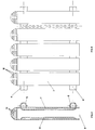
- the radiator shown in fig. 1 and 2 comprises a series of prismatic elements in each of which is provided an intermediate space defined between the outer tube 1 which forms the element and an inner tube 2, said intermediate space being traversed by hot water coming from the pipe d '' supply 3 and leaving through the return line 4.
- each element 1 there remains a vertical duct which is open at its two ends and which is crossed by the air which, under the effect of convection, moves from bottom to top while being heated by hot water circulating between the walls opposite the tubes 1 and 2.
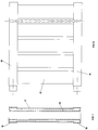
- the hot water brought in through the pipe 5 and leaving through the pipe 6 passes through the intermediate space formed between the outer tube or element 7 and the inner tube 8, as in FIG. 1 and 2.
- the difference relates to the fact that the air which penetrates through the lower hole 9 escapes upwards through slots 10 provided at the upper part of each element.
- Fig 5 and 6 illustrate a second variant in which the supply pipes 11 and return 12 for hot water are constituted by hollow connections which assemble the various elements of the radiator to each other, which are thus supplied by the center and no longer by the side.
- each element comprises an outer tube 13 inside which is provided an inner wall 14 to define an intermediate space intended for the circulation of hot water for heating the air which passes through each element from bottom to top.
- the hot water supply and return are operated using prismatic conduits 15 and 16 defined by the upper, respectively lower, elements of the radiator, this water naturally circulating in space intermediate formed between the tubular casing 17 of each element and an inner tube 18.
- each element contains an intermediate space for the circulation of hot water and that the air passes vertically from bottom to high by convection the interior wall of said space.
Landscapes
- Engineering & Computer Science (AREA)
- Physics & Mathematics (AREA)
- Thermal Sciences (AREA)
- Mechanical Engineering (AREA)
- General Engineering & Computer Science (AREA)
- Domestic Hot-Water Supply Systems And Details Of Heating Systems (AREA)
- Central Heating Systems (AREA)
- Resistance Heating (AREA)
Abstract
L'eau chaude circule à travers un espace intermédiaire ménagé au niveau de chaque élément du radiateur entre un tube ou enveloppe extérieure 1 et un tube ou paroi intérieure (2), tandis que l'air passe par convection à l'intérieur dudit tube ou paroi (2). Le brevet décrit plusieurs formes de réalisation, en ce qui concerne notamment les canalisations d'adduction (3) et de retour (4) destinés à l'eau chaude.
Description
- La présente invention a pour objet le radiateur de chauffage à eau chaude qui est défini à la revendication 1 et dont l'originalité réside principalement dans le fait que chacun de ses éléments comprend un espace intermédiaire à l'intérieur duquel circule l'eau chaude en vue de chauffer l'air qui traverse intérieurement ledit élément de bas en haut par tirage naturel pour réchauffer l'atmosphère ambiante.
- Cette disposition de base est susceptible d'être mise en oeuvre pour la réalisation de différents types de radiateurs qui diffèrent par le fait que les tubes d'adduction et de retour de l'eau peuvent passer à l'extérieur ou à l'intérieur de l'appareil et que le passage intérieur de l'air peut être prévu de différentes façons.
- Dans tous les cas l'invention permet de réduire très sensiblement le volume d'eau renfermé par chaque élément du radiateur et de conférer la faculté de réaliser un espace intermédiaire de volume déterminé en modifiant les dimensions extérieures et intérieures des deux tubes qui définissent cet espace intermédiaire.
- Le dessin annexé, donné à titre d'exemple, permettra de mieux comprendre l'invention, les caractéristiques qu'elle présente et les avantages qu'elle est susceptible de procurer :
- Fig. 1 est une coupe transversale illustrant une première forme de réalisation du radiateur de chauffage suivant l'invention.
- Fig. 2 est une vue en élévation partielle de ce radiateur.
- Fig. 3 et 4, 5 et 6, 7 et 8 illustrent de la même manière trois variantes de mise en oeuvre de l'invention.
- Le radiateur représenté en fig. 1 et 2 comprend une série d'éléments prismatiques dans chacun desquels est ménagé un espace intérmédiaire défini entre le tube extérieur 1 qui forme l'élément et un tube intérieur 2, ledit espace intermédiaire étant parcouru par l'eau chaude provenant de la canalisation d'adduction 3 et sortant par la canalisation de retour 4.
- A l'intérieur de chaque élément 1 subsiste un conduit vertical qui est ouvert à ses deux extrémités et qui est traversé par l'air qui, sous l'effet de la convection, se déplace de bas en haut en étant chauffé par l'eau chaude circulant entre les parois en vis-à-vis des tubes 1 et 2.
- Dans la forme de réalisation illustrée en fig 3 et 4, l'eau chaude amenée par la canalisation 5 et sortant par la canalisation 6 traverse l'espace intermédiaire ménagé entre le tube extérieur ou élément 7 et le tube intérieur 8, comme en fig. 1 et 2. La différence porte sur le fait que l'air qui pénétre par l'ouie inférieure 9 s'échappe vers le haut à travers des fentes 10 prévues à la partie supérieure de chaque élément.
- Fig 5 et 6 illustrent une deuxième variante dans laquelle les canalisations d'adduction 11 et de retour 12 pour l'eau chaude sont constituées par les raccords creux qui assemblent les uns aux autres les différents éléments du radiateur, lesquels sont ainsi alimentés par le centre et non plus par le côté. Bien entendu, chaque élément comprend un tube extérieur 13 à l'intérieur duquel est prévu une paroi intérieure 14 pour définir un espace intermédiaire destiné à la circulation d'eau chaude pour le chauffage de l'air qui traverse chaque élément de bas en haut.
- Dans la forme de réalisation suivant fig. 7 et 8, l'adduction et le retour de l'eau chaude sont opérés à l'aide de conduits prismatiques 15 et 16 définis par la partie supérieure, respectivement inférieure, des éléments du radiateur, cette eau circulant bien entendu dans l'espace intermédiaire ménagé entre l'enveloppe tubulaire 17 de chaque élément et un tube intérieur 18.
- On conçoit qu'on pourrait imaginer d'autres formes de réalisation du radiateur à eau chaude suivant l'invention, pour autant que chaque élément renferme un espace intermédiaire pour la circulation de l'eau chaude et que l'air traverse verticalement de bas en haut par convection la paroi interieure dudit espace.
Claims (4)
- Radiateur de chauffage à eau chaude, du genre comprenant une série d'éléments reliés par une canalisation supérieure d'adduction d'eau chaude (3, 5, 15) et par une canalisation inférieure de retour (4, 6, 16), caractérisé en ce que chaque élément est constitué par un tube ou enveloppe extérieure (1, 7, 13, 17) et un tube ou paroi intérieure (2, 8, 14, 18) qui définissent entre eux un espace intermédiaire pour la circulation de l'eau entre les canalisations précitées, tandis que l'air à chauffer traverse verticalement par convection le tube ou paroi inférieure.
- Radiateùr suivant la revendication 1, caractérisé en ce que la partie supérieure de chaque élément est dotée d'une grille (10) pour la sortie de l'air chaud.
- Radiateur suivant l'une ou l'autre des revendications 1 et 2, caractérisé en ce que les canalisations d'adduction (11) et de retour (12) sont constitués par les raccords centraux qui assemblent les éléments.
- Radiateur suivant l'une quelconque des revendications 1 et 2, caractérisé en ce que les canalisations d'adduction (15) et de retour (16) sont constituées par les extrémités supérieure et inférieure, à profil prismatique, de l'enveloppe extérieure (17) des éléments.
Priority Applications (3)
| Application Number | Priority Date | Filing Date | Title |
|---|---|---|---|
| ITVI930032A IT1270583B (it) | 1993-03-08 | 1993-03-08 | Radiatore tubolare per riscaldamento |
| DE4408065A DE4408065A1 (de) | 1993-03-08 | 1994-03-05 | Röhrenheizkörper |
| EP94201388A EP0683370A1 (fr) | 1993-03-08 | 1994-05-17 | Radiateur de chauffage à eau chaude |
Applications Claiming Priority (2)
| Application Number | Priority Date | Filing Date | Title |
|---|---|---|---|
| ITVI930032A IT1270583B (it) | 1993-03-08 | 1993-03-08 | Radiatore tubolare per riscaldamento |
| EP94201388A EP0683370A1 (fr) | 1993-03-08 | 1994-05-17 | Radiateur de chauffage à eau chaude |
Publications (1)
| Publication Number | Publication Date |
|---|---|
| EP0683370A1 true EP0683370A1 (fr) | 1995-11-22 |
Family
ID=26136268
Family Applications (1)
| Application Number | Title | Priority Date | Filing Date |
|---|---|---|---|
| EP94201388A Withdrawn EP0683370A1 (fr) | 1993-03-08 | 1994-05-17 | Radiateur de chauffage à eau chaude |
Country Status (3)
| Country | Link |
|---|---|
| EP (1) | EP0683370A1 (fr) |
| DE (1) | DE4408065A1 (fr) |
| IT (1) | IT1270583B (fr) |
Cited By (1)
| Publication number | Priority date | Publication date | Assignee | Title |
|---|---|---|---|---|
| CN101818996A (zh) * | 2010-03-17 | 2010-09-01 | 夏贤 | 一种高效节能热交换器 |
Families Citing this family (1)
| Publication number | Priority date | Publication date | Assignee | Title |
|---|---|---|---|---|
| EP1087196A3 (fr) * | 1999-09-22 | 2003-09-03 | HAGETEC Handelsgesellschaft für Haustechnik mbH | Radiateur |
Citations (4)
| Publication number | Priority date | Publication date | Assignee | Title |
|---|---|---|---|---|
| FR825954A (fr) * | 1936-12-03 | 1938-03-18 | Radiateur alimenté par l'eau chaude, par la vapeur ou par l'électricité et chauffant par circulation d'air | |
| FR1537499A (fr) * | 1967-09-21 | 1968-08-23 | Radiateur, notamment pour installation de chauffage central | |
| DE2805164A1 (de) * | 1978-02-08 | 1979-08-09 | Hans Loose | Konvektions-waermetauscher fuer heizzwecke |
| EP0381028A1 (fr) * | 1989-01-30 | 1990-08-08 | Bernhard Schnittker | Echangeur de chaleur plan |
-
1993
- 1993-03-08 IT ITVI930032A patent/IT1270583B/it active IP Right Grant
-
1994
- 1994-03-05 DE DE4408065A patent/DE4408065A1/de not_active Ceased
- 1994-05-17 EP EP94201388A patent/EP0683370A1/fr not_active Withdrawn
Patent Citations (4)
| Publication number | Priority date | Publication date | Assignee | Title |
|---|---|---|---|---|
| FR825954A (fr) * | 1936-12-03 | 1938-03-18 | Radiateur alimenté par l'eau chaude, par la vapeur ou par l'électricité et chauffant par circulation d'air | |
| FR1537499A (fr) * | 1967-09-21 | 1968-08-23 | Radiateur, notamment pour installation de chauffage central | |
| DE2805164A1 (de) * | 1978-02-08 | 1979-08-09 | Hans Loose | Konvektions-waermetauscher fuer heizzwecke |
| EP0381028A1 (fr) * | 1989-01-30 | 1990-08-08 | Bernhard Schnittker | Echangeur de chaleur plan |
Cited By (1)
| Publication number | Priority date | Publication date | Assignee | Title |
|---|---|---|---|---|
| CN101818996A (zh) * | 2010-03-17 | 2010-09-01 | 夏贤 | 一种高效节能热交换器 |
Also Published As
| Publication number | Publication date |
|---|---|
| ITVI930032A0 (it) | 1993-03-08 |
| ITVI930032A1 (it) | 1994-09-08 |
| DE4408065A1 (de) | 1994-09-15 |
| IT1270583B (it) | 1997-05-06 |
Similar Documents
| Publication | Publication Date | Title |
|---|---|---|
| FR2471553A1 (fr) | Capteur de chaleur pouvant etre installe notamment dans une cheminee domestique et procede pour porter a une temperature plus elevee un fluide tel que de l'eau | |
| FR2526146A1 (fr) | Echangeur de chaleur a element d'echange dispose a l'interieur d'un caisson | |
| CA1252442A (fr) | Aerotherme | |
| EP2013547A1 (fr) | Chauffe-eau plat | |
| FR2565334A1 (fr) | Chaudiere a condensation par voie seche | |
| EP0006196B2 (fr) | Chauffe-eau, en particulier pour cafetière ménagère | |
| FR2753527A1 (fr) | Echangeur de chaleur gaz-liquide, et appareil de production d'eau chaude comprenant un tel echangeur de chaleur | |
| FR1464778A (fr) | échangeur thermique | |
| CH340517A (fr) | Appareil thermique | |
| FR2719894A1 (fr) | Echangeur de chaleur destiné au chauffage des habitations - Bureaux - Ateliers etc.... | |
| US855197A (en) | Water-heater. | |
| FR2577019A1 (fr) | Installation de chauffage pour cheminee a foyer ouvert et tirage inverse | |
| FR2627265A1 (fr) | Echangeur thermique compact | |
| FR2468852A1 (fr) | Chaudiere, notamment pour installations de chauffage domestique | |
| FR2681670A1 (fr) | Echangeur mixte chauffage-eau chaude, a serpentin de rechauffage sanitaire sans soudure. | |
| FR2484612A1 (fr) | Dispositif de recuperation et de distribution de la chaleur pour atre de cheminee | |
| BE638929A (fr) | ||
| FR2627262A1 (fr) | Chaudiere verticale pour le chauffage de fluides caloporteurs | |
| US608889A (en) | Radiator | |
| FR2529995A1 (fr) | Chaudiere d'atre | |
| FR2466735A1 (fr) | Echangeur de chaleur et plus particulierement preparateur d'eau chaude sanitaire | |
| BE701844A (fr) | ||
| FR2592138A3 (fr) | Chaudiere amenageable a cheminee interne. | |
| BE636978A (fr) | ||
| BE524358A (fr) |
Legal Events
| Date | Code | Title | Description |
|---|---|---|---|
| PUAI | Public reference made under article 153(3) epc to a published international application that has entered the european phase |
Free format text: ORIGINAL CODE: 0009012 |
|
| AK | Designated contracting states |
Kind code of ref document: A1 Designated state(s): AT BE CH DK ES FR GB LI NL SE |
|
| STAA | Information on the status of an ep patent application or granted ep patent |
Free format text: STATUS: THE APPLICATION IS DEEMED TO BE WITHDRAWN |
|
| 18D | Application deemed to be withdrawn |
Effective date: 19960523 |