EP0683376B1 - Projectile tiré par canon assisté par propulseur aérobie - Google Patents
Projectile tiré par canon assisté par propulseur aérobie Download PDFInfo
- Publication number
- EP0683376B1 EP0683376B1 EP95107567A EP95107567A EP0683376B1 EP 0683376 B1 EP0683376 B1 EP 0683376B1 EP 95107567 A EP95107567 A EP 95107567A EP 95107567 A EP95107567 A EP 95107567A EP 0683376 B1 EP0683376 B1 EP 0683376B1
- Authority
- EP
- European Patent Office
- Prior art keywords
- projectile
- fuel
- air
- scramjet
- mode
- Prior art date
- Legal status (The legal status is an assumption and is not a legal conclusion. Google has not performed a legal analysis and makes no representation as to the accuracy of the status listed.)
- Expired - Lifetime
Links
- 239000000446 fuel Substances 0.000 claims description 59
- 238000002485 combustion reaction Methods 0.000 claims description 19
- 230000006835 compression Effects 0.000 claims description 10
- 238000007906 compression Methods 0.000 claims description 10
- 239000012530 fluid Substances 0.000 claims description 10
- 239000007789 gas Substances 0.000 claims description 7
- 238000002347 injection Methods 0.000 claims description 7
- 239000007924 injection Substances 0.000 claims description 7
- 230000008602 contraction Effects 0.000 claims description 4
- 239000002360 explosive Substances 0.000 claims description 3
- 230000006641 stabilisation Effects 0.000 claims description 3
- 238000011105 stabilization Methods 0.000 claims description 3
- 239000003570 air Substances 0.000 claims 6
- 239000012080 ambient air Substances 0.000 claims 4
- 230000005465 channeling Effects 0.000 claims 2
- 230000001419 dependent effect Effects 0.000 claims 1
- 238000010304 firing Methods 0.000 claims 1
- 230000000977 initiatory effect Effects 0.000 claims 1
- 230000001133 acceleration Effects 0.000 description 12
- 238000013461 design Methods 0.000 description 9
- 238000002156 mixing Methods 0.000 description 6
- 230000035939 shock Effects 0.000 description 5
- 230000003068 static effect Effects 0.000 description 5
- 230000007423 decrease Effects 0.000 description 4
- 239000007788 liquid Substances 0.000 description 4
- 230000000694 effects Effects 0.000 description 3
- 239000003380 propellant Substances 0.000 description 3
- 238000011160 research Methods 0.000 description 3
- 238000000926 separation method Methods 0.000 description 3
- 239000000126 substance Substances 0.000 description 3
- 238000013459 approach Methods 0.000 description 2
- 238000011161 development Methods 0.000 description 2
- 238000009826 distribution Methods 0.000 description 2
- 230000001747 exhibiting effect Effects 0.000 description 2
- 239000002828 fuel tank Substances 0.000 description 2
- 238000010438 heat treatment Methods 0.000 description 2
- 230000003993 interaction Effects 0.000 description 2
- 238000000034 method Methods 0.000 description 2
- 239000000203 mixture Substances 0.000 description 2
- 230000029058 respiratory gaseous exchange Effects 0.000 description 2
- 229920002379 silicone rubber Polymers 0.000 description 2
- 238000003860 storage Methods 0.000 description 2
- 238000012360 testing method Methods 0.000 description 2
- 239000004429 Calibre Substances 0.000 description 1
- 238000010276 construction Methods 0.000 description 1
- 230000007812 deficiency Effects 0.000 description 1
- 238000010494 dissociation reaction Methods 0.000 description 1
- 230000005593 dissociations Effects 0.000 description 1
- 239000013536 elastomeric material Substances 0.000 description 1
- 238000005516 engineering process Methods 0.000 description 1
- 230000003628 erosive effect Effects 0.000 description 1
- 238000002474 experimental method Methods 0.000 description 1
- 230000005484 gravity Effects 0.000 description 1
- 230000010354 integration Effects 0.000 description 1
- 238000004519 manufacturing process Methods 0.000 description 1
- 239000000463 material Substances 0.000 description 1
- 238000012986 modification Methods 0.000 description 1
- 230000004048 modification Effects 0.000 description 1
- 230000001141 propulsive effect Effects 0.000 description 1
- 238000005215 recombination Methods 0.000 description 1
- 230000006798 recombination Effects 0.000 description 1
- 238000004513 sizing Methods 0.000 description 1
- 239000007787 solid Substances 0.000 description 1
- 239000004449 solid propellant Substances 0.000 description 1
- 238000012549 training Methods 0.000 description 1
- 238000011144 upstream manufacturing Methods 0.000 description 1
Images


Classifications
-
- F—MECHANICAL ENGINEERING; LIGHTING; HEATING; WEAPONS; BLASTING
- F42—AMMUNITION; BLASTING
- F42B—EXPLOSIVE CHARGES, e.g. FOR BLASTING, FIREWORKS, AMMUNITION
- F42B15/00—Self-propelled projectiles or missiles, e.g. rockets; Guided missiles
-
- F—MECHANICAL ENGINEERING; LIGHTING; HEATING; WEAPONS; BLASTING
- F02—COMBUSTION ENGINES; HOT-GAS OR COMBUSTION-PRODUCT ENGINE PLANTS
- F02K—JET-PROPULSION PLANTS
- F02K7/00—Plants in which the working fluid is used in a jet only, i.e. the plants not having a turbine or other engine driving a compressor or a ducted fan; Control thereof
- F02K7/10—Plants in which the working fluid is used in a jet only, i.e. the plants not having a turbine or other engine driving a compressor or a ducted fan; Control thereof characterised by having ram-action compression, i.e. aero-thermo-dynamic-ducts or ram-jet engines
Definitions
- the present invention relates to high speed gun or artillery launched projectiles, and more particularly to airbreathing propulsion-assisted projectiles which accelerate after launch using a combination of ramjet and scramjet propulsion to enable flight at hypersonic velocities.
- the ramjet and supersonic ramjet (scramjet) propulsion cycles for supersonic and hypersonic (Mach > 5) engines are well-known within the art of aerospace propulsion.
- an engine defined by an external compression device or forebody, an internal compression device such as an inlet including a diffuser and an isolator, a combustion device or combustor, and an expansion device or nozzle. All surfaces wetted by flow streamlines ultimately passing through the engine are considered to be a part of the engine flowpath since they contribute to the engine cycle performance. Consequently, the integration of the airframe and the propulsion systems for vehicles or projectiles employing these propulsion cycles is critical for high performance.
- the main advantage of scramjet propulsion is that supersonic velocities within the combustion chamber are accompanied by lower static temperatures, pressures, and reduced total pressure losses.
- reduced temperatures increase combustion efficiency, reduced pressures decrease loads on engine structure, and reduced total pressure losses (entropy gains) increase the flow energy available for thrust production.
- the purpose of the inlet is to capture a desired quantity of air flow and deliver it to the combustor at a desired pressure and Mach number with a minimum of entropy producing losses.
- the technology and parameters necessary to successfully design and operate an efficient supersonic inlet are well-known but difficult to capture in a single design.
- the mass flow captured by the inlet compared to the drag of the vehicle must be sufficiently large that a net thrust can be expected across the entire Mach number range of operation for achievable values of ramjet or scramjet I sp performance.
- the isolator (also known as a constant area diffuser) is located between the inlet and the combustor entrance, and is necessary to adjust flow static pressure from that of the inlet exit to the higher combustor pressure downstream during ramjet and early scramjet ("dual-mode") operation.
- dual-mode ramjet and early scramjet
- An isolator permits a shock train to develop between the inlet and combustor with a near normal shock static pressure rise without any upstream inlet interaction. The length of the isolator is critical to carrying out this function.
- the combustor provides the physical domain for injecting a liquid or gaseous fuel into high velocity air and mixing the fuel and air for combustion.
- the fluid and chemical phenomena present in the combustor are extremely complex and include the effects of laminar and turbulent mixing of fuel injection jets with boundary layers and core flows, and the finite rate chemical kinetics of the exothermic combustion reactions.
- Fuel ignition and flameholding are also important issues. Some of the typical design parameters are the fuel injection geometry, mixing enhancement devices, and the length of the combustor required to achieve the high mixing and combustion efficiencies necessary for high Isp performance across the Mach number range of interest.
- Fuel injection location and mixing rate i.e., distribution of heat release
- Fuel is generally injected aft in ramjet mode, both fore and aft in dual-mode (combined supersonic and subsonic combustion), and forward in scramjet mode.
- the nozzle or expansion system is important to the specific impulse Isp of the projectile because it produces thrust by accelerating the high static pressure flow exiting the combustor to lower pressure and high velocity (i.e., momentum).
- the objective is to expand the high pressure flow to the lowest pressure possible using a shape that minimizes the combination of friction losses, chemical recombination losses, and flow divergence (angularity) losses.
- the ratio of the nozzle expansion area to the inlet capture area and the ratio of inlet mass flow to nonflowpath drag are critical figures of merit in designing a system which produces a flowpath thrust that exceeds the nonflowpath drag and therefore produces acceleration. Balancing the geometric details for high efficiencies and high Isp performance with the vehicle drag is the traditional challenge inherent in ramjet and scramjet vehicle design.
- rocket-assisted projectile A rocket motor containing a solid or liquid propellant is incorporated into the base of the projectile and ignited after leaving the barrel.
- the range and acceleration potential of these rocket assisted projectiles is rather limited due to the small amount of fuel which can be carried and the relatively low I sp which can be produced by a rocket motor in comparison to an air breathing ramjet or scramjet propulsion cycle.
- US Patent No. 4,291,533 to Dugger et al. describes a rocket-launched scramjet powered missile.
- Botwin et al. in US Patent No. 4,428,293 addresses the payload and fuel volume issues of the previously referenced patents to Olson et al. and Flatau.
- Botwin specifically discloses that the ramjet powered projectile is designed to maintain a thrust-to-drag balance such that it follows a predetermined vacuum ballistic trajectory.
- a scramjet system launched from a light gas gun for scramjet propulsion testing and experiments in a closed test chamber was documented in 1968 by H.H. King and O. P. Prachar in the Air Force Aero Propulsion Laboratory Technical Report AFAPL-TR-68-9.
- This study represents the only known attempt to launch a scramjet-shaped projectile from a gun barrel, and was conducted to investigate issues pertaining to launch and acceptable free flight of an annular combustor scramjet model.
- the scramjet model was too small to include a fuel system, and was therefore limited to unfueled launches to verify structural integrity and aerodynamic stability. Fuel systems were tested separately in simple cones only, not in scramjets.
- the design of the model included an internal contraction ratio (i.e., the ratio of the inlet area at the cowl leading edge to the minimum flow area downstream of the cowl leading edge) of unity for positive inlet starting characteristics, but with a very low airflow capture area to drag ratio with the result that a net thrust or positive acceleration could not be produced even if it was fueled.
- an internal contraction ratio i.e., the ratio of the inlet area at the cowl leading edge to the minimum flow area downstream of the cowl leading edge
- U.S. Patent No. 3,974,648 to Kepler describes a variable geometry ramjet engine capable of operation over the Mach 3 to 12 speed range.
- the key element of the ramjet engine is a movable cowl around a center body in order to vary inlet capture and nozzle expansion areas. Such an engine is not suitable for application to the high acceleration environment of gun launched projectiles.
- EP-A-0 417 012 relates to a connecting device for the sabot of a sub-calibre projectile, especially of the kinetic-energy arrow type.
- the sabot has a front pocket delimited by the widened front surface of a plurality of component elements capable of being spread apart by an aerodynamic effect.
- the front pocket contains an elastomeric material selected from silicone elastomers, rubber or hot-vulcanisable materials.
- Another object of the present invention is to provide a novel air-breathing, propulsion-assisted projectile which is capable of acceleration from initial ramjet combustor operation at supersonic projectile velocities to scramjet combustor operation at hypersonic velocities.
- Still another object of the invention is to provide an air-breathing propulsion-assisted projectile which is capable of accelerating from initial scramjet combustor operation at high supersonic or low hypersonic velocities to scramjet combustor operation at high hypersonic velocities.
- Still another object of the invention is to provide an air-breathing propulsion-assisted projectile which can use either liquid or gaseous fuels.
- Yet another object of the invention is to provide a structurally efficient design which incorporates an integral ramjet or scramjet inlet, a combustor, a nozzle, a fuel storage tank, and a payload storage cavity, where the design is able to withstand the high acceleration loads of a gun launch.
- Still another object of the invention is to provide an air-breathing propulsion assisted projectile which can fly long range at low flight path angle trajectories with high terminal velocities, or which can fly high flight path angle trajectories to deliver suborbital and orbital payloads.
- the projectile assembly of the present invention which includes a forebody having an air compression surface, an engine assembly disposed in a mid-region of the body and including an encompassing cowl disposed about the circumference of the body mid-region, and a nozzle section disposed rearwardly of the engine assembly.
- the projectile assembly also includes a sabot or container-like shell which encircles the rearward portion of the nozzle section, and protects that region of the projectile from the explosive gases generated by the gun in which the projectile sits until it is fired from the gun.
- the cowl leading edge portion is configured to cooperate with the external surface of the projectile to capture the air which has been compressed by, and is leaving, the compression surface of the projectile body.
- the facing surfaces of the cowl and the body are configured to define therebetween a throat in which takes place further compression of the air, introduction of fuel, and expansion of the combusted air-and-fuel.
- the rear end portion of the cowl is configured to direct the exiting combusted air-and-fuel mixture over the nozzle section of the projectile.
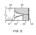
- FIGs 1 and 5 illustrate a scramjet projectile 10 according to the present invention, which includes a projectile assembly 20 and a sabot assembly 30 (shown in Figure 5).
- the projectile of assembly 20 has a forebody 104 exhibiting a compression surface, a cowl 106 enclosing an engine assembly (to be discussed in detail when referring to the embodiment of the projectile shown in Figure 2), a scramjet nozzle 107 exhibiting an expansion surface, and aerodynamic stabilization fins 108.
- the forebody 104 must have an external surface configured to compress the fluid (i.e., air) as the projectile travels in its trajectory.
- the cowl 106 includes a leading edge 105 which preferably is notched to provide a low drag coefficient and low aerodynamic heating.
- the use of fins 108 is desirable insofar as it tends to stabilize the projectile.
- the sabot assembly 30 comprises a plurality of annular segments 109 which are attachable to one another to form a hollow shell.
- the downstream, or trailing, end of the shell is closed by an end piece (not shown, but designated by reference numeral 120), and all the shell components and the end piece, when assembled together, form a container.
- the sabot assembly receives the trailing or nozzle end of the projectile (see 214, 221 in Figure 2a) in a snug fit, and protects the nozzle end from the explosive gases of the gun when the latter is fired.
- the sections 109 of the sabot assembly separate from one another along separation lines 130 (see Figures 1 and 5) and from the rear (aft) end of the projectile nozzle. In this manner, operation of the engine assembly can be initiated, and the projectile assembly can then accelerate onward in its trajectory.
- FIG. 1 a preferred embodiment 200 of the projectile assembly illustrated in Figure 1, which includes a forebody 204 having an external compression surface C extending from the projectile nosetip 203 rearwardly to the vicinity of the leading edge of the cowl 202, and an external expansion surface or nozzle 221 extending from the vicinity of the trailing edge of the cowl rearwardly.
- the projectile also includes an internal volume for fuel systems and a payload bay 215.
- the cowl 202 surrounds the body 204 in such a manner as to create an engine internal flowpath defined by an inlet region 205, an isolator region 206, and a combustor region 208 and an internal nozzle 209.
- the cowl 202 is supported by splitters 216 spaced circumferentially about the projectile body. Although not a critical feature of the structure, the cowl leading edge (see 105 in Figure 1) is notched for each internal flowpath in order to provide sweep relative to the axial direction for lower drag, aerodynamic heating and inlet starting characteristics.
- the splitters serve to segregate the neighboring internal flowpaths which are individually fueled by fuel injectors 207 located in the combustor region 208. While not shown in these Figures, fuel injectors may also be located in the splitters.
- the fuel tank 210 contained within the body is connected to the fuel injectors via a fueling control valve 218, fuel lines 211 and 213, and distribution and pressure equalizing manifolds 212.
- the fuel control valve 218 provides a mechanism for loading fuel into the tank and for preventing fuel from reaching the fuel injectors prior to leaving the gun barrel.
- the fuel line 211 is routed very close to the wall of the combustor region 208 in order to cool the wall and add heat to the fuel prior to its reaching the injector 207.
- the tank 210 must be pressurized by a pressurization system 219 which imparts a force to the piston or diaphragm 220 once the projectile clears the gun barrel.
- the pressurization profile of the system coupled with the fuel lines 211 and 213, the manifolding 212, and the orifice size of the fuel injectors may be used to tailor the injected fuel mass flow rate as a function of the projectile flight time.
- the fuel tank could be pressurized through the fuel control valve 218.
- the fuel lines 211, 213, the manifolding 212, and the orifice size of the fuel injectors 207 could again be used to tailor the injected gaseous fuel mass flow rate as a function of the projectile flight time.
- the stability of the scramshell projectile 200 after launch is provided by a plurality of stabilization fins 217 integrated with selected splitters. Although not shown, the span of these fins and hence their area could be increased beyond the barrel diameter using devices located within the fins and deployed after the projectile clears the barrel 110.
- the stability of the projectile within the gun barrel is provided by the sabot assembly 30 which protects the rear end of the projectile from the high pressure gun blast initially propelling the projectile and provides a mechanism for transferring the force of the blast to the high strength projectile base 214.
- the aerodynamic loads on the sabot sections causes the sections of the sabot "container" to separate from one another as well as from the projectile itself.
- a release mechanism within the sabot "container" such as a spring, could also cause the sections to separate and the "container" to dissociate itself from the rear end of the projectile.
- the projectile assembly clears the end of the gun barrel at supersonic or near-hypersonic velocities.
- the sabot "container" separates from the projectile, and nearly simultaneously with the separation event, the fuel is injected into the combustor region 208 where it is ignited.
- the projectile will accelerate from the supersonic or near-hypersonic launch velocity to a higher velocity as long as sufficient air is captured by the inlet defined between the cowl leading edge and the projectile body.
- the thrust produced is sufficient to exceed the drag of the projectile.
- the specific impulse for a ramjet cycle is high for Mach numbers between 2 and 5, and decreases as the Mach number increases. Transitioning to scramjet propulsion at about Mach 6, the specific impulse continues to decline, but at a reduced rate in comparison to the ramjet cycle. In order to compensate for the declining specific impulse with Mach number trend, the air captured by the inlet must increase with the increasing Mach number to retain the desired high levels of thrust.
- Figures 3 and 4 show schematically how the flow structure changes between the supersonic launch Mach number and a higher hypersonic Mach number in order to provide increasing air capture.
- the angle of the bow shock 303 is steep relative to the longitudinal axis of the projectile. Consequently, the streamline 305, which represents the outer boundary of fluid flow passing through the internal flowpath, is relatively close to the body.
- this streamline when rotated about the axis of symmetry, defines a circular "capture" area (depicted at 306) through which the air mass encountered by the projectile inlet passes. Air outside the streamline is pushed outside the cowl 302 and does not contribute to the development of thrust for the projectile.
- the angle of the bow shock 303 relative to the longitudinal axis of the projectile becomes smaller, as shown at 403.
- the streamline 305 moves farther away from the body as shown at 405, thus increasing the air captured by the inlet 406, and partially, if not entirely, offsetting the increased drag at the higher Mach numbers.
- the nozzle expansion area 309 and 409 remains constant, insofar as it is a function only of the projected area of the flowpath base. Consequently, the ratio of the nozzle expansion area 309 to the inlet capture area 306 at supersonic speeds decreases with increasing Mach number as illustrated at 409 and 406.
- the ratio of expansion to capture areas is high and supports high propulsion efficiency, high thrust to drag ratios, and high projectile accelerations to quickly reach higher velocities.
- the projectile of the invention exhibits a lower, yet adequate, expansion to capture area ratio such that good propulsion performance is obtained.
- the air-breathing propulsion-assisted projectile is capable of flying low flight path angle trajectories over long distances unachievable by conventional unpowered ballistic projectiles. This is feasible by sizing the projectile such that after a supersonic launch, it accelerates to the design supersonic or hypersonic Mach number where thrust equals drag and contains enough fuel to provide airbreathing thrust for the length of the flight.
- the air-breathing projectile of the invention is capable of flying high flight path angle or lofted trajectories which reach altitudes unachievable by conventional unpowered ballistic projectiles.
- a thrusting projectile By accelerating through the high density lower portion of the atmosphere with a thrusting projectile, higher velocities and thus greater altitudes can be reached in comparison to the coasting and decelerating unpowered projectile.
- a larger payload mass can be delivered to a given altitude using the airbreathing propulsion-assisted projectile of the present invention than can be obtained using the conventional, unpowered projectiles.
Landscapes
- Engineering & Computer Science (AREA)
- Chemical & Material Sciences (AREA)
- Combustion & Propulsion (AREA)
- General Engineering & Computer Science (AREA)
- Mechanical Engineering (AREA)
- Aviation & Aerospace Engineering (AREA)
- Testing Of Engines (AREA)
- Toys (AREA)
Claims (17)
- Projectile assisté par propulsion aérobie (10) adapté pour être tiré à partir d'un canon à des vitesses supérieures à Mach 1, comportant :un moteur incluant un trajet d'écoulement à géométrie fixe pour générer une poussée supérieure à une traínée, de sorte que ledit projectile (10) accélère pendant la totalité de son cycle de fonctionnement moteur.
- Projectile (10) selon la revendication 1, dans lequel ledit moteur comportelesdits moyens de direction (202) et ledit corps (204) coopérant avec le fluide ambiant pour produire une poussée supérieure à une traction lorsque ledit projectile (10) se déplace à des vitesses supérieures à Mach 1.un corps (204) ayant un tronçon de compression extérieur (C), un tronçon de compression intérieur, un tronçon de combustion (208), et un tronçon de tuyère (209), etune alimentation en combustible (210) isolée dudit tronçon de combustion (208),des moyens (202) pour diriger du fluide ambiant vers ledit tronçon de combustion (208) du corps,
- Projectile (10) selon la revendication 2, dans lequel ledit tronçon de compression intérieur définit un passage ayant un rapport de contraction interne supérieur à un.
- Projectile (10) selon la revendication 2, et comportant de plus des moyens (207, 210, 211, 212, 213, 218) pour alimenter du combustible au niveau dudit tronçon de combustion (208).
- Projectile (10) selon la revendication 2, dans lequel ledit tronçon de tuyère (209) a un diamètre extérieur, et comportant de plus une pluralité d'ailettes de stabilisation espacées circonférentiellement (217) situées dans ledit diamètre extérieur dudit tronçon de tuyère (209) dudit corps (207) pour protéger lesdites ailettes (217) des parois du fût de canon pendant un tir du projectile à partir dudit canon.
- Projectile selon la revendication 2, et comportant de plus un ensemble formant sabot (30) fixé de manière amovible sur la partie arrière dudit corps (204), ledit ensemble formant sabot comportant une pluralité d'éléments (109) qui sont réunis ensemble autour de la partie arrière du corps, et qui forment un boítier pour protéger la partie arrière du corps des gaz explosifs dans le fût (110) dudit canon.
- Projectile selon la revendication 6, et comportant de plusdes moyens (207, 210, 211, 212, 213, 218) pour alimenter du combustible au niveau dudit tronçon de combustion, etdes moyens, accouplés à au moins un de ladite pluralité d'éléments (109), pour déclencher le fonctionnement desdits moyens de fourniture de combustible lorsque ladite pluralité d'éléments (109) se séparent dudit projectile lorsqu'il sort dudit fût de canon (110).
- Projectile selon la revendication 2, dans lequel ledit corps comporte de plus un compartiment de charge utile (215).
- Projectile selon la revendication 2, dans lequel lesdits moyens de fourniture de combustible comportent une source de combustible (210), des vannes de commande (218) et des lignes d'acheminement de combustible (211, 212, 213) connectant la source de combustible au tronçon de combustion (208) du corps (204).
- Projectile assisté par propulsion aérobie (10) ayant un trajet d'écoulement à géométrie fixe, pouvant se déplacer à des vitesses supérieures à Mach 1, comportant :
un moteur incluantdes premiers moyens (C ; 202 ; 208 ; 221) pour comprimer de l'air ambiant circulant au-delà dudit projectile (10), canaliser ledit air comprimé à travers un passage, brûler ledit air canalisé, et dilater ledit air brûlé dans un premier mode de fonctionnement de statoréacteur, etdes seconds moyens (C ; 202, 208 ; 221) pour comprimer de l'air ambiant, canaliser ledit air comprimé à travers ledit passage, brûler ledit air canalisé, et dilater ledit air brûlé dans un second mode de fonctionnement de statoréacteur à combustion supersonique. - Projectile (10) selon la revendication 10, et comportant de plus des moyens pour effectuer une transition dudit mode de fonctionnement à partir dudit premier mode de fonctionnement de statoréacteur vers ledit second mode de fonctionnement de statoréacteur à combustion supersonique pendant le cycle opérationnel dudit moteur.
- Projectile selon la revendication 10 ou 11, dans lequel lesdits moyens de transition comportent des moyens pour faire fonctionner à la fois le mode de moteur de statoréacteur et le mode de moteur de statoréacteur à combustion supersonique simultanément.
- Projectile à lancement au canon assisté par une propulsion aérobie, comportant :un corps ayant un trajet d'écoulement intérieur (205, 206, 208, 209) à géométrie fixe, ledit trajet d'écoulement comportant une entrée (205) ayant un rapport de contraction supérieur à 1, un dispositif d'isolation (206), un dispositif de combustion (208) et une tuyère intérieure (209),ledit trajet d'écoulement permettant le fonctionnement du projectile (10) dans un mode de statoréacteur, un mode de statoréacteur à combustion supersonique ou une combustion de modes de statoréacteur et de statoréacteur à combustion supersonique.
- Projectile aérobie selon la revendication 13, dans lequel ledit corps comporte de plus des moyens d'injection de combustible (207), et le mode de fonctionnement du projectile (10) dépend de la vitesse du projectile (10) à travers le fluide ambiant, et du positionnement du combustible introduit dans le trajet d'écoulement par les moyens d'injection de combustible (207).
- Projectile aérobie (10) selon la revendication 13, dans lequel ledit corps comporte de plus des moyens (C) pour comprimer de l'air ambiant, un capot (202) entourant le corps en aval desdits moyens de compression (C), des moyens d'injection de combustible (207), et des moyens d'alimentation en combustible (210, 218, 211, 213, 212) isolés dudit trajet d'écoulement intérieur,
ledit capot (202) comportant des moyens pour créer des écoulements définis dudit air ambiant comprimé pour acheminement desdits écoulements à partir de ladite entrée (205) vers ledit dispositif de combustion (208), et dans lequel lesdits moyens d'injection de combustible (207) font communiquer ladite alimentation en combustible avec ledit dispositif de combustion (208). - Projectile aérobie (10) selon la revendication 14, dans lequel ladite tuyère intérieure (209) comporte des moyens de dilatation de fluide au niveau de l'extrémité arrière dudit capot (202).
- Projectile aérobie (10) selon la revendication 16, dans lequel ledit corps comporte de plus des moyens de dilatation de fluide (221) à l'arrière dudit capot (202).
Applications Claiming Priority (2)
| Application Number | Priority Date | Filing Date | Title |
|---|---|---|---|
| US08/245,130 US5513571A (en) | 1994-05-17 | 1994-05-17 | Airbreathing propulsion assisted gun-launched projectiles |
| US245130 | 1994-05-17 |
Publications (2)
| Publication Number | Publication Date |
|---|---|
| EP0683376A1 EP0683376A1 (fr) | 1995-11-22 |
| EP0683376B1 true EP0683376B1 (fr) | 2002-09-04 |
Family
ID=22925410
Family Applications (1)
| Application Number | Title | Priority Date | Filing Date |
|---|---|---|---|
| EP95107567A Expired - Lifetime EP0683376B1 (fr) | 1994-05-17 | 1995-05-17 | Projectile tiré par canon assisté par propulseur aérobie |
Country Status (6)
| Country | Link |
|---|---|
| US (1) | US5513571A (fr) |
| EP (1) | EP0683376B1 (fr) |
| JP (1) | JPH0849999A (fr) |
| AU (1) | AU699240B2 (fr) |
| DE (1) | DE69528012T2 (fr) |
| IL (1) | IL113500A (fr) |
Cited By (1)
| Publication number | Priority date | Publication date | Assignee | Title |
|---|---|---|---|---|
| RU2724626C1 (ru) * | 2020-01-27 | 2020-06-25 | Акционерное общество "Федеральный научно-производственный центр "Алтай" | Бронебойный активно-реактивный снаряд |
Families Citing this family (17)
| Publication number | Priority date | Publication date | Assignee | Title |
|---|---|---|---|---|
| US5485787A (en) * | 1994-06-21 | 1996-01-23 | Rockwell International Corporation | Gas gun launched scramjet test projectile |
| WO1998001506A1 (fr) * | 1996-07-03 | 1998-01-15 | Shell Internationale Research Maatschappij B.V. | Composition elastomere/huile/polyolefine thermoplastique a faible teneur d'arene |
| DE69701399T2 (de) * | 1996-07-03 | 2000-09-07 | Shell Internationale Research Maatschappij B.V., Den Haag | Thermoplastische hoch 1,2 - enthaltende elastomer-öl-polyolefin zusammensetzung |
| US5853143A (en) * | 1996-12-23 | 1998-12-29 | Boeing North American, Inc. | Airbreathing propulsion assisted flight vehicle |
| US6058846A (en) * | 1998-06-03 | 2000-05-09 | Lockhead Martin Corporation | Rocket and ramjet powered hypersonic stealth missile having alterable radar cross section |
| US6536350B2 (en) | 2001-03-07 | 2003-03-25 | The United States Of America As Represented By The United States Department Of Energy | Stagnation pressure activated fuel release mechanism for hypersonic projectiles |
| WO2003016849A2 (fr) * | 2001-08-13 | 2003-02-27 | Allied Aerospace Industries, Inc. | Procede et appareil de test de moteurs |
| US8955791B2 (en) | 2012-05-10 | 2015-02-17 | The Boeing Company | First and second stage aircraft coupled in tandem |
| US9109864B2 (en) * | 2012-11-02 | 2015-08-18 | Christopher V. Beckman | Missile with mid-flight oxidizer charging |
| UA113654C2 (xx) * | 2015-01-14 | 2017-02-27 | Спосіб гіперзвукового захисту танка гальченко і модуль комплексу активного його захисту | |
| US9488455B1 (en) * | 2015-01-22 | 2016-11-08 | Consolidated Nuclear Security, LLC | Sabot assembly |
| RU2685002C2 (ru) * | 2017-07-25 | 2019-04-16 | Федеральное государственное бюджетное учреждение науки Институт теоретической и прикладной механики им. С.А. Христиановича Сибирского отделения Российской академии наук (ИТПМ СО РАН) | Ракета с воздушно-реактивным двигателем |
| CN107972892A (zh) * | 2018-01-08 | 2018-05-01 | 梁思武 | 一种卷吸助推运载火箭 |
| CN108489331B (zh) * | 2018-04-02 | 2023-07-21 | 中国工程物理研究院流体物理研究所 | 一种具有剪切式弹丸的轻气炮 |
| CN109915282B (zh) * | 2019-04-04 | 2020-03-20 | 中国人民解放军国防科技大学 | 应用于火箭基组合循环发动机的自适应火箭喷管 |
| CN110208149B (zh) * | 2019-04-28 | 2021-09-17 | 南京航空航天大学 | 一种砂粒速度和方向精准可控的砂粒投放装置 |
| RU2724629C1 (ru) * | 2020-02-03 | 2020-06-25 | Акционерное общество "Федеральное научно-производственный центр "Алтай" | Бронебойный активно-реактивный снаряд |
Family Cites Families (11)
| Publication number | Priority date | Publication date | Assignee | Title |
|---|---|---|---|---|
| US2989922A (en) * | 1953-02-17 | 1961-06-27 | Marvin H Greenwood | Ramjet propulsion device |
| US4291533A (en) * | 1965-12-30 | 1981-09-29 | The United States Of America As Represented By The Secretary Of The Navy | Supersonic ramjet missile |
| US3974648A (en) * | 1968-08-19 | 1976-08-17 | United Technologies Corporation | Variable geometry ramjet engine |
| US4539911A (en) * | 1979-06-20 | 1985-09-10 | The United States Of America As Represented By The Secretary Of The Army | Projectile |
| US4428293A (en) * | 1980-12-19 | 1984-01-31 | United Technologies Corporation | Gun-launched variable thrust ramjet projectile |
| IL82472A (en) * | 1986-06-05 | 1993-01-14 | Gen Electric | Ram jet armament system |
| US4936219A (en) * | 1989-08-10 | 1990-06-26 | The United States Of America As Represented By The Secretary Of The Army | Fin protection device |
| FR2651570B1 (fr) * | 1989-09-07 | 1991-11-22 | France Etat Armement | Dispositif de liaison pour sabot de projectile sous-calibre. |
| US5058826A (en) * | 1990-01-29 | 1991-10-22 | General Electric Company | Scramjet engine having a low pressure combustion cycle |
| US5067406A (en) * | 1990-11-05 | 1991-11-26 | The United States Of America As Represented By The Secretary Of The Army | Supersonic, low-drag, solid fuel ramjet tubular projectile |
| US5224344A (en) * | 1992-09-04 | 1993-07-06 | The United States Of America As Represented By The Secretary Of The Navy | Variable-cycle storable reactants engine |
-
1994
- 1994-05-17 US US08/245,130 patent/US5513571A/en not_active Expired - Fee Related
-
1995
- 1995-04-26 IL IL113500A patent/IL113500A/en unknown
- 1995-05-16 JP JP7116707A patent/JPH0849999A/ja active Pending
- 1995-05-16 AU AU20080/95A patent/AU699240B2/en not_active Ceased
- 1995-05-17 EP EP95107567A patent/EP0683376B1/fr not_active Expired - Lifetime
- 1995-05-17 DE DE69528012T patent/DE69528012T2/de not_active Expired - Fee Related
Cited By (1)
| Publication number | Priority date | Publication date | Assignee | Title |
|---|---|---|---|---|
| RU2724626C1 (ru) * | 2020-01-27 | 2020-06-25 | Акционерное общество "Федеральный научно-производственный центр "Алтай" | Бронебойный активно-реактивный снаряд |
Also Published As
| Publication number | Publication date |
|---|---|
| IL113500A (en) | 1998-02-08 |
| DE69528012D1 (de) | 2002-10-10 |
| AU699240B2 (en) | 1998-11-26 |
| IL113500A0 (en) | 1995-07-31 |
| EP0683376A1 (fr) | 1995-11-22 |
| DE69528012T2 (de) | 2003-04-30 |
| AU2008095A (en) | 1995-11-23 |
| JPH0849999A (ja) | 1996-02-20 |
| US5513571A (en) | 1996-05-07 |
Similar Documents
| Publication | Publication Date | Title |
|---|---|---|
| US5513571A (en) | Airbreathing propulsion assisted gun-launched projectiles | |
| US5853143A (en) | Airbreathing propulsion assisted flight vehicle | |
| US5578783A (en) | RAM accelerator system and device | |
| US4938112A (en) | Apparatus and method for the acceleration of projectiles to hypervelocities | |
| US6536350B2 (en) | Stagnation pressure activated fuel release mechanism for hypersonic projectiles | |
| US4539911A (en) | Projectile | |
| EP0248340B1 (fr) | Système de lancement pour projectiles | |
| US5224344A (en) | Variable-cycle storable reactants engine | |
| US5485787A (en) | Gas gun launched scramjet test projectile | |
| US5067406A (en) | Supersonic, low-drag, solid fuel ramjet tubular projectile | |
| US7051659B2 (en) | Projectile structure | |
| US20230193856A1 (en) | Multi-mode propulsion system | |
| US6981364B2 (en) | Combine engine for single-stage spacecraft | |
| Webster | Liquid fueled integral rocket/ramjet technology review | |
| JP2020522427A (ja) | 膨出部を有するアイソレータを伴うフライトビークルエアエンジン | |
| US20060112674A1 (en) | Semi-axisymmetric scramjet flowpath with conformal nozzle | |
| US11655055B2 (en) | System and method for aerodynamic drag reduction in airborne systems and vehicles | |
| RU2751311C1 (ru) | Способ увеличения дальности полета активно-реактивного снаряда и активно-реактивный снаряд с моноблочной комбинированной двигательной установкой (варианты) | |
| US3273334A (en) | Ramjet missile | |
| US5317866A (en) | Free-flying tubular vehicle | |
| US4338783A (en) | Two-stage hypersonic ramjet | |
| US4170875A (en) | Caseless rocket design | |
| KR20250113770A (ko) | 고체 램제트 발사체 | |
| KR20250095640A (ko) | 고체 연료 추진 발사체 | |
| Limage et al. | Combined ducted rocket and solid fuel ramjet cycle |
Legal Events
| Date | Code | Title | Description |
|---|---|---|---|
| PUAI | Public reference made under article 153(3) epc to a published international application that has entered the european phase |
Free format text: ORIGINAL CODE: 0009012 |
|
| AK | Designated contracting states |
Kind code of ref document: A1 Designated state(s): DE FR GB |
|
| 17P | Request for examination filed |
Effective date: 19960522 |
|
| 17Q | First examination report despatched |
Effective date: 19980917 |
|
| GRAG | Despatch of communication of intention to grant |
Free format text: ORIGINAL CODE: EPIDOS AGRA |
|
| RIN1 | Information on inventor provided before grant (corrected) |
Inventor name: CERVISI, RICHARD T. Inventor name: BOWCUTT, KEVIN G. Inventor name: GRANTZ, ARTHUR C. |
|
| GRAG | Despatch of communication of intention to grant |
Free format text: ORIGINAL CODE: EPIDOS AGRA |
|
| GRAH | Despatch of communication of intention to grant a patent |
Free format text: ORIGINAL CODE: EPIDOS IGRA |
|
| GRAH | Despatch of communication of intention to grant a patent |
Free format text: ORIGINAL CODE: EPIDOS IGRA |
|
| GRAA | (expected) grant |
Free format text: ORIGINAL CODE: 0009210 |
|
| AK | Designated contracting states |
Kind code of ref document: B1 Designated state(s): DE FR GB |
|
| REG | Reference to a national code |
Ref country code: GB Ref legal event code: FG4D |
|
| REF | Corresponds to: |
Ref document number: 69528012 Country of ref document: DE Date of ref document: 20021010 |
|
| ET | Fr: translation filed | ||
| PGFP | Annual fee paid to national office [announced via postgrant information from national office to epo] |
Ref country code: GB Payment date: 20030514 Year of fee payment: 9 |
|
| PGFP | Annual fee paid to national office [announced via postgrant information from national office to epo] |
Ref country code: FR Payment date: 20030520 Year of fee payment: 9 |
|
| PGFP | Annual fee paid to national office [announced via postgrant information from national office to epo] |
Ref country code: DE Payment date: 20030626 Year of fee payment: 9 |
|
| PLBE | No opposition filed within time limit |
Free format text: ORIGINAL CODE: 0009261 |
|
| STAA | Information on the status of an ep patent application or granted ep patent |
Free format text: STATUS: NO OPPOSITION FILED WITHIN TIME LIMIT |
|
| 26N | No opposition filed |
Effective date: 20030605 |
|
| PG25 | Lapsed in a contracting state [announced via postgrant information from national office to epo] |
Ref country code: GB Free format text: LAPSE BECAUSE OF NON-PAYMENT OF DUE FEES Effective date: 20040517 |
|
| PG25 | Lapsed in a contracting state [announced via postgrant information from national office to epo] |
Ref country code: DE Free format text: LAPSE BECAUSE OF NON-PAYMENT OF DUE FEES Effective date: 20041201 |
|
| GBPC | Gb: european patent ceased through non-payment of renewal fee |
Effective date: 20040517 |
|
| PG25 | Lapsed in a contracting state [announced via postgrant information from national office to epo] |
Ref country code: FR Free format text: LAPSE BECAUSE OF NON-PAYMENT OF DUE FEES Effective date: 20050131 |
|
| REG | Reference to a national code |
Ref country code: FR Ref legal event code: ST |