EP0683385B1 - Verfahren und Vorrichtung zur Beurteilung der Schubkraft eines Staustrahltriebwerks - Google Patents
Verfahren und Vorrichtung zur Beurteilung der Schubkraft eines Staustrahltriebwerks Download PDFInfo
- Publication number
- EP0683385B1 EP0683385B1 EP95400840A EP95400840A EP0683385B1 EP 0683385 B1 EP0683385 B1 EP 0683385B1 EP 95400840 A EP95400840 A EP 95400840A EP 95400840 A EP95400840 A EP 95400840A EP 0683385 B1 EP0683385 B1 EP 0683385B1
- Authority
- EP
- European Patent Office
- Prior art keywords
- combustion chamber
- bladder
- nozzle
- ramjet
- combustion
- Prior art date
- Legal status (The legal status is an assumption and is not a legal conclusion. Google has not performed a legal analysis and makes no representation as to the accuracy of the status listed.)
- Expired - Lifetime
Links
- 238000000034 method Methods 0.000 title claims description 17
- 238000002485 combustion reaction Methods 0.000 claims description 103
- 239000012530 fluid Substances 0.000 claims description 27
- 239000000446 fuel Substances 0.000 claims description 11
- 238000007664 blowing Methods 0.000 claims description 6
- 238000006073 displacement reaction Methods 0.000 claims description 6
- 238000002347 injection Methods 0.000 claims description 5
- 239000007924 injection Substances 0.000 claims description 5
- 230000003068 static effect Effects 0.000 claims 1
- 235000021183 entrée Nutrition 0.000 description 5
- 238000005259 measurement Methods 0.000 description 5
- 210000004027 cell Anatomy 0.000 description 2
- 230000006835 compression Effects 0.000 description 2
- 238000007906 compression Methods 0.000 description 2
- 230000000284 resting effect Effects 0.000 description 2
- RRHGJUQNOFWUDK-UHFFFAOYSA-N Isoprene Chemical compound CC(=C)C=C RRHGJUQNOFWUDK-UHFFFAOYSA-N 0.000 description 1
- 230000000694 effects Effects 0.000 description 1
- 229920001971 elastomer Polymers 0.000 description 1
- 239000000463 material Substances 0.000 description 1
- 238000012986 modification Methods 0.000 description 1
- 230000004048 modification Effects 0.000 description 1
- 239000008188 pellet Substances 0.000 description 1
- 230000002093 peripheral effect Effects 0.000 description 1
- 229920001195 polyisoprene Polymers 0.000 description 1
- XLYOFNOQVPJJNP-UHFFFAOYSA-N water Substances O XLYOFNOQVPJJNP-UHFFFAOYSA-N 0.000 description 1
Images

Classifications
-
- G—PHYSICS
- G01—MEASURING; TESTING
- G01L—MEASURING FORCE, STRESS, TORQUE, WORK, MECHANICAL POWER, MECHANICAL EFFICIENCY, OR FLUID PRESSURE
- G01L5/00—Apparatus for, or methods of, measuring force, work, mechanical power, or torque, specially adapted for specific purposes
- G01L5/13—Apparatus for, or methods of, measuring force, work, mechanical power, or torque, specially adapted for specific purposes for measuring the tractive or propulsive power of vehicles
- G01L5/133—Apparatus for, or methods of, measuring force, work, mechanical power, or torque, specially adapted for specific purposes for measuring the tractive or propulsive power of vehicles for measuring thrust of propulsive devices, e.g. of propellers
Definitions
- the present invention relates to a method for estimating the thrust of a ramjet, a method for optimizing the combustion chamber of a ramjet, as well as a device for implementing these methods.
- the engine to be tested is usually mounted on a particularly complex test bench. Then, said motor is operated and its thrust is determined from the measurement of the longitudinal force generated by said motor in operation.
- Such a measurement requires means, such as displacement sensors, which are extremely precise and therefore complex.
- the complexity of the means used on the test bench is due, in particular, to the need to determine many corrective terms used to calculate the effective thrust of the engine and often difficult to measure, such as for example the external drag or the drag of pellet.
- the object of the present invention applied exclusively to a ramjet, is to remedy said drawbacks existing when determining the thrust, in the case where the thrust of a ramjet to be determined must not be measured exactly, but only estimated.
- the invention relates to a method for estimating the thrust of a ramjet in a simple manner and at reduced cost.
- the initial resting pressure of the fluid in the bladder is fixed at a positive level. So we can measure positive and negative pressure variations relative to this level and therefore the thrust, whether positive or negative.
- Said method according to the invention for estimating the thrust of a ramjet can be implemented in numerous and varied applications. It can for example be used to compare the propulsion performance of different ramjet engines, or to optimize the combustion chamber of a ramjet engine.
- the present invention further relates to a method making it possible to determine, among different internal arrangements of the combustion chamber of a ramjet, the optimal arrangement for which the ramjet exhibits the maximum thrust, for identical operating conditions.
- Said method therefore makes it possible to optimize the combustion chamber of a ramjet, since it makes it possible to determine the internal arrangement of the combustion chamber for which the thrust of the ramjet estimated by the value of the pressure of the bladder fluid is the highest.
- the present invention also relates to a device for implementing any one of the above-mentioned methods.
- Said bladder can obviously be produced in different ways, for example in the form of flexible bags with reduced volume angularly distributed between said nozzle and said inlet face of the combustion chamber.
- said bladder is produced in the form of a closed tube, forming a torus whose axis is coaxial with said nozzle and said combustion chamber.
- said device comprises a first connection flange secured to said nozzle and a second connection flange secured to the inlet face of said combustion chamber, said flexible bladder being mounted between said first and second connection flanges.
- an intermediate piece is provided between said first and second connecting flanges and two flexible bladders, one between said first flange and said intermediate piece, the other between this last piece and said second flange.
- At least said first connection flange has a groove in which said bladder is housed, and said intermediate piece arranged between said first and second connection flanges has a protruding part which penetrates into said groove and the external face is in contact with said flexible bladder.
- connection zone between said nozzle and said combustion chamber the internal diameters of said nozzle, said first and second connection flanges and said combustion chamber are substantially identical, which makes it possible to obtain at the level from said connection zone, a regular flow of air blown through said nozzle into said combustion chamber.
- said first and second connection flanges are connected together by means of clamping screws provided with an elastic system tending to bring said first and second flanges closer to one another.
- Figure 1 is a schematic sectional view of a device according to the invention.
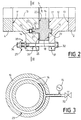
- FIG. 2 is an enlarged view, in section, of the connection zone between the combustion chamber and the nozzle, shown diagrammatically in FIG. 1.
- Figure 3 is a schematic partial section along the line III-III of Figure 2, schematically illustrating the connection between the flexible tube and the means for measuring the pressure.
- the device 1 according to the invention and shown in Figure 1 is used to estimate the thrust of a ramjet. Said estimation is carried out in accordance with the invention by mounting only the combustion chamber 2 of said ramjet to be tested on said device 1.
- the combustion chamber 2, of axis XX is mounted on said fixed support 3 by means of articulation means 6, of known type, so that said combustion chamber 2 is immobile in the transverse direction, but has a partial freedom of longitudinal movement, approximately along said axis XX.
- the nozzle 4 with symmetry of revolution is mounted, for its part, by means of feet 7 on said support 3 coaxially with the axis X-X.
- Said nozzle 4 may also have a rectangular or square section.
- Said blowing means comprise, in addition to said nozzle 4, an air supply system, not shown, arranged near the inlet face 8 of said nozzle 4, making it possible to blow air into the latter, as is will see this in more detail below. Furthermore, said nozzle has in its middle part 9 a significant reduction in diameter so as to allow air circulation through said nozzle 4 in forced flow.
- the device 1 comprises a first connection flange 10 fixed on the rear face 11 of said nozzle 4 and a second connection flange 12 fixed on the front face 13 of the combustion chamber 2.
- an intermediate piece 16 is arranged cooperatively between said first and second connecting flanges 10 and 12.
- the rear face 17 of said intermediate piece 16 is arranged in contact with the front face 18 of the second flange of connection 12.
- the intermediate part 16 is provided on said rear face 17 with a protruding part 19 which enters the assembled position, presenting a peripheral contact, in a recess 20 formed in correspondence in the front face 18 of said second connecting flange 12.
- the first connecting flange 10 is provided, for its part, on its rear face 22, facing the intermediate piece 16, with a groove 23 in which is housed said flexible tube 14 disposed in contact with the bottom 24 of said groove 23 Said groove 23 has a circular shape transversely to said first connection flange 10, as can be seen in FIG. 3.
- the intermediate part 16 has on its front face 25 a projecting part 26 formed in correspondence with said groove 23.
- Said first and second connecting flanges 10 and 12 are held together by means of identical clamping screws 29 distributed radially around said parts, outside the nozzle 4 and the combustion chamber 2.
- Each of said clamping screws 29 passes through holes 30 and 31 made facing each other in said connection flanges 10 and 12 and is held by its head 32 mounted on the side of the second connection flange 12.
- Each of said clamping screws 29 is further provided on the side opposite to the head 32 of an elastic system 33, comprising for example a spring, locked between a nut 34 mounted on the screw 29 and the first connecting flange 10.
- fuel injection devices 21 are arranged in said combustion chamber 2 towards the inlet 2A of the latter, as shown in FIG. 1, said fuel injection devices 21 being intended to supply fuel. said combustion chamber 2.
- a thrust illustrated by arrows B is exerted on the combustion chamber 2, causing the displacement of said combustion chamber 2 in the direction indicated by said arrows B.
- This displacement is transmitted via the second connection flange 12 secured to the combustion chamber 2 to the intermediate piece 16 which compresses the flexible tube 14 via the protruding part 26, since the first connection flange 10 carrying said flexible tube 14 and secured to said nozzle 4 is fixed.
- This compression then causes an increase in the pressure of the fluid contained in said flexible tube 14, measured by the measuring means 15.
- Said estimation of the thrust can obviously be carried out for variable operating points, corresponding for example to the operation, in a determined flight domain, of an aircraft powered by such a ramjet.
- the embodiment of the device according to the invention shown in the figures is provided only by way of example.
- Other embodiments are obviously possible, in particular as regards the bladder which, instead of being produced in the form of a flexible tube, can be produced for example in the form of flexible bags distributed angularly around the connection zone between the nozzle and the combustion chamber.
- said bladder can be compressed in dependence on the longitudinal movement of the combustion chamber and that the pressure of the fluid which it contains is therefore representative of the thrust of the ramjet.
- the device 1 can have many applications. For example, it can be used to compare the thrust of different ramjet engines, by successively mounting the combustion chambers of these ramjet engines on said device 1 and by measuring the pressure inside the flexible tube during an air supply to said chambers combustion.
- the device 1 according to the invention is used to optimize the combustion chamber of a ramjet.
- the pressure of the fluid contained in the flexible tube 14 is measured for determined operating conditions, the combustion chamber being of course mounted on the device according to the invention in the manner described above.
- the arrangement for which the measured pressure is highest is therefore determined to be the best possible.
- the device according to the present invention also makes it possible to estimate a negative thrust, on condition that the initial resting pressure of the fluid in said bladder is fixed at a positive level.
Landscapes
- Chemical & Material Sciences (AREA)
- Engineering & Computer Science (AREA)
- Combustion & Propulsion (AREA)
- Ocean & Marine Engineering (AREA)
- Physics & Mathematics (AREA)
- General Physics & Mathematics (AREA)
- Measuring Fluid Pressure (AREA)
- Testing Of Engines (AREA)
- Portable Nailing Machines And Staplers (AREA)
- Force Measurement Appropriate To Specific Purposes (AREA)
Claims (10)
- Verfahren zur Beurteilung der Schubkraft eines Staustrahltriebwerks, dadurch gekennzeichnet, daß:a) die Brennkammer (2) des Staustrahltriebwerks an stationär angebrachten Mitteln (3, 6) montiert wird, die der Brennkammer (2) eine teilweise Bewegungsfreiheit in Längsrichtung verleihen;b) am Eintritt (2A) der Brennkammer (2) Gebläsemittel mit einer stationär angebrachten Düse (4) angeordnet werden;c) zwischen der Düse (4) und dem Eintritt (2A) der Brennkammer (2) mindestens eine mit einem Fluid gefüllte flexible Blase (14) angeordnet wird, die mit einem Mittel (15) zur Messung des Drucks des Fluids in der Blase (14) verbunden ist;d) durch die Düse (4) in die Brennkammer (2) Luft geblasen wird, so daß in der Brennkammer (2) Versorgungsbedingungen geschaffen werden, wie sie bei einem bestimmten Betrieb des Staustrahltriebwerks gegeben sind;e) die Brennkammer (2) mit Kraftstoff versorgt wird, so daß eine Verbrennung stattfinden kann, undf) der Druck des Fluids in der Blase (14) gemessen wird, der sich aus der Bewegung der Brennkammer (2) gegenüber der Düse (4) bei der Verbrennung ergibt.
- Verfahren nach Anspruch 1,
dadurch gekennzeichnet, daß der Anfangsruhedruck des Fluids in der Blase auf ein positives Niveau festgelegt wird. - Verfahren, um unter verschiedenen Innenanordnungen der Brennkammer (2) eines Staustrahltriebwerks die optimale Anordnung zu bestimmen, bei der das Staustrahltriebwerk die maximale Schubkraft aufweist,
dadurch gekennzeichnet, daß- für jede der verschiedenen Innenanordnungen der Brennkammer (2) die Stufen a) bis f) des Verfahrens nach Anspruch 1 ausgeführt und in jeder der Stufen d) und e) erneut die gleichen Versorgungsbedingungen in der Brennkammer (2) geschaffen werden;- die Meßdrücke des Fluids in der Blase (14) miteinander verglichen werden und- als optimale Anordnung die Anordnung der Brennkammer (2) bestimmt wird, bei der der Druck des Fluids der Blase am höchsten ist. - Vorrichtung zur Anwendung eines der in den Ansprüchen 1 bis 3 dargelegten Verfahren,
dadurch gekennzeichnet, daß sie umfaßt:- stationär angebrachte Mittel (3, 6), an denen die Brennkammer (2) eines zu prüfenden Staustrahltriebwerks so montiert wird, daß diese eine teilweise Bewegungsfreiheit in Längsrichtung aufweist;- Mittel zum Einblasen von Luft mit einer stationär angebrachten Düse (4), die am Eintritt (2A) der Brennkammer (2) angeordnet sind, die mit mindestens einer Kraftstoffeinspritzvorrichtung (21) ausgestattet ist;- mindestens eine flexible Blase (14), die mit einem Fluid gefüllt und zwischen der Düse (4) und dem Eintritt (2A) der Brennkammer (2) angeordnet ist, und- ein Mittel (15), das mit der Blase (14) verbunden ist, um den Druck des Fluids in der Blase (14) zu messen. - Vorrichtung nach Anspruch 4,
dadurch gekennzeichnet, daß die Blase in Form eines geschlossenen Schlauchs (14) ausgeführt ist. - Vorrichtung nach einem der Ansprüche 4 oder 5,
dadurch gekennzeichnet, daß sie einen ersten Verbindungsflansch (10), der mit der Düse (4) verbunden ist, und einen zweiten Verbindungsflansch (12), der mit der Eintrittsseite (2A) der Brennkammer (2) verbunden ist, hat, wobei zwischen dem ersten und zweiten Verbindungsflansch (10, 12) mindestens eine flexible Blase (14) angeordnet ist. - Vorrichtung nach Anspruch 6,
dadurch gekennzeichnet, daß ein Zwischenteil (16) zwischen dem ersten und zweiten Verbindungsflansch (10, 12) angeordnet ist, und dadurch, daß zwei flexible Blasen (14) vorgesehen sind, eine zwischen dem ersten Flansch (10) und dem Zwischenteil (16) und die andere zwischen diesem Zwischenteil und dem zweiten Flansch (12). - Vorrichtung nach Anspruch 6,
dadurch gekennzeichnet, daß mindestens der erste Verbindungsflansch (10) eine Kehle (23) hat, in der die Blase (14) gelagert ist, und dadurch, daß ein Zwischenteil (16) zwischen dem ersten und zweiten Verbindungsflansch (10, 12) ein überstehendes Teil (26) hat, das in die Kehle eingreift und dessen Außenseite (27) mit der flexiblen Blase (14) in Verbindung steht. - Vorrichtung nach einem der Ansprüche 6 oder 8,
dadurch gekennzeichnet, daß die Innendurchmesser der Düse (4), des ersten und zweiten Verbindungsflanschs (10, 12) und der Brennkammer (2) in der Verbindungszone zwischen der Düse (4) und der Brennkammer (2) etwa identisch sind. - Vorrichtung nach einem der Ansprüche 6 bis 9,
dadurch gekennzeichnet, daß der erste und zweite Verbindungsflansch (10, 12) durch Spannschrauben (29) mit einem elastischen System (33), durch das der erste und zweite Flansch aneinander angestellt werden können, miteinander verbunden sind.
Applications Claiming Priority (2)
| Application Number | Priority Date | Filing Date | Title |
|---|---|---|---|
| FR9406058 | 1994-05-18 | ||
| FR9406058A FR2720159B1 (fr) | 1994-05-18 | 1994-05-18 | Procédé et dispositif pour l'estimation de la poussée d'un statoréacteur. |
Publications (2)
| Publication Number | Publication Date |
|---|---|
| EP0683385A1 EP0683385A1 (de) | 1995-11-22 |
| EP0683385B1 true EP0683385B1 (de) | 1997-03-05 |
Family
ID=9463306
Family Applications (1)
| Application Number | Title | Priority Date | Filing Date |
|---|---|---|---|
| EP95400840A Expired - Lifetime EP0683385B1 (de) | 1994-05-18 | 1995-04-13 | Verfahren und Vorrichtung zur Beurteilung der Schubkraft eines Staustrahltriebwerks |
Country Status (6)
| Country | Link |
|---|---|
| US (1) | US5589632A (de) |
| EP (1) | EP0683385B1 (de) |
| JP (1) | JPH07325018A (de) |
| CA (1) | CA2149074A1 (de) |
| DE (1) | DE69500169T2 (de) |
| FR (1) | FR2720159B1 (de) |
Cited By (1)
| Publication number | Priority date | Publication date | Assignee | Title |
|---|---|---|---|---|
| CN100392371C (zh) * | 2006-07-31 | 2008-06-04 | 北京航空航天大学 | 一种适用于空间微小推力发动机的推力测量系统 |
Families Citing this family (14)
| Publication number | Priority date | Publication date | Assignee | Title |
|---|---|---|---|---|
| US5831155A (en) * | 1996-12-02 | 1998-11-03 | Atlantic Research Corporation | Apparatus and method for simulating rocket-to-ramjet transition in a propulsion system |
| GB2384058B (en) * | 2002-01-15 | 2005-11-30 | Rolls Royce Plc | Thrust correction |
| US20050081598A1 (en) * | 2003-10-17 | 2005-04-21 | Bruno Tongiani | Method and apparatus for calibrating seal force testing devices |
| CN105043772B (zh) * | 2015-07-13 | 2018-07-03 | 西安航天动力测控技术研究所 | 固体冲压发动机自由射流三工况试验方法 |
| CN105841972B (zh) * | 2016-04-26 | 2019-04-30 | 中科合肥微小型燃气轮机研究院有限责任公司 | 用于燃气轮机试验台的调心装置 |
| CN108225713B (zh) * | 2017-12-29 | 2021-01-26 | 重庆大学 | 连续式跨声速风洞喷管段半柔壁喉块的竖直强制同步式电动驱动装置 |
| CN108362465B (zh) * | 2017-12-29 | 2021-11-09 | 中国空气动力研究与发展中心设备设计及测试技术研究所 | 连续式跨声速风洞半柔壁面喷管喉块竖直空间式电动驱动装置 |
| CN109387370B (zh) * | 2018-11-14 | 2023-12-22 | 中国空空导弹研究院 | 一种冲压发动机直连式高空模拟试验无轴向力进气系统 |
| CN109540526B (zh) * | 2018-12-09 | 2021-10-15 | 西安航天动力试验技术研究所 | 一种用于冲压发动机直连试验中涡轮引射系统 |
| CN109883646A (zh) * | 2018-12-21 | 2019-06-14 | 中国航天空气动力技术研究院 | 一种基于高温脉冲风洞的吸气式推进试验模拟方法 |
| CN109738196B (zh) * | 2019-01-18 | 2020-07-31 | 中国人民解放军国防科技大学 | 一种基于地面直连试验的冲压发动机性能天地换算方法 |
| KR102419316B1 (ko) * | 2020-05-13 | 2022-07-11 | 국방과학연구소 | 받음각 모의 부재 및 이를 적용한 직접 연결식 초음속 엔진 시험 장치 |
| CN111811823A (zh) * | 2020-06-05 | 2020-10-23 | 北京动力机械研究所 | 一种适用于冲压发动机自由射流试验的台架结构 |
| CN115875673B (zh) * | 2022-12-20 | 2026-02-27 | 中国空气动力研究与发展中心空天技术研究所 | 一种应用于高温空气来流的脉冲燃烧风洞氢氧燃烧加热器 |
Family Cites Families (10)
| Publication number | Priority date | Publication date | Assignee | Title |
|---|---|---|---|---|
| US3038331A (en) * | 1958-06-10 | 1962-06-12 | Curtiss Wright Corp | Apparatus for measuring reaction engine thrust |
| US3210991A (en) * | 1961-11-17 | 1965-10-12 | Weekley Edward Elijah | Engine test benches |
| US3537303A (en) * | 1968-09-06 | 1970-11-03 | Us Navy | Pendulum thrust test stand |
| US3788130A (en) * | 1972-10-18 | 1974-01-29 | A Ormond | Low interaction multi load cell system for measuring thrust |
| US4328703A (en) * | 1980-02-14 | 1982-05-11 | Avco Corporation | Thrust measuring test stand |
| GB2096776A (en) * | 1981-03-12 | 1982-10-20 | Froude Eng Ltd | Improvements in or relating to thrust stands |
| DE3631923A1 (de) * | 1986-09-19 | 1988-03-31 | Hanno Ernst | Vorrichtung zum messen von druckkraeften |
| US4788855A (en) * | 1987-03-03 | 1988-12-06 | The Boeing Company | Test apparatus for measuring jet engine thrust |
| FR2664051B1 (fr) * | 1990-06-27 | 1993-12-24 | Snecma | Balance de mesure de la poussee d'un turbo reacteur. |
| US5235848A (en) * | 1991-11-27 | 1993-08-17 | The United States Of America As Represented By The Secretary Of The Navy | Thruster test fixture |
-
1994
- 1994-05-18 FR FR9406058A patent/FR2720159B1/fr not_active Expired - Fee Related
-
1995
- 1995-04-13 DE DE69500169T patent/DE69500169T2/de not_active Expired - Fee Related
- 1995-04-13 EP EP95400840A patent/EP0683385B1/de not_active Expired - Lifetime
- 1995-05-09 US US08/437,058 patent/US5589632A/en not_active Expired - Fee Related
- 1995-05-11 CA CA002149074A patent/CA2149074A1/fr not_active Abandoned
- 1995-05-16 JP JP7117306A patent/JPH07325018A/ja not_active Ceased
Cited By (1)
| Publication number | Priority date | Publication date | Assignee | Title |
|---|---|---|---|---|
| CN100392371C (zh) * | 2006-07-31 | 2008-06-04 | 北京航空航天大学 | 一种适用于空间微小推力发动机的推力测量系统 |
Also Published As
| Publication number | Publication date |
|---|---|
| CA2149074A1 (fr) | 1995-11-19 |
| DE69500169T2 (de) | 1997-06-12 |
| US5589632A (en) | 1996-12-31 |
| JPH07325018A (ja) | 1995-12-12 |
| FR2720159A1 (fr) | 1995-11-24 |
| EP0683385A1 (de) | 1995-11-22 |
| FR2720159B1 (fr) | 1996-07-26 |
| DE69500169D1 (de) | 1997-04-10 |
Similar Documents
| Publication | Publication Date | Title |
|---|---|---|
| EP0683385A1 (de) | Verfahren und Vorrichtung zur Beurteilung der Schubkraft eines Staustrahltriebwerks | |
| EP0280622A1 (de) | Kolben für Brennkraftmaschinen | |
| EP1571080A1 (de) | Aufhängevorrichtung eines Flugzeugtriebwerks an einem Flügelpylon | |
| EP0461943B1 (de) | Verdichtungsvorrichtung, insbesondere zur Druckfüllung eines Behälters | |
| FR2834043A1 (fr) | Ensemble de serrage perfectionne et coupleur hydraulique le comportant | |
| EP0416966A2 (de) | Pneumatischer Servomotor | |
| EP0100716B1 (de) | Koordinatentaster mit einem Laser | |
| FR2718506A1 (fr) | Soupape de limitation de pression et procédé de réglage d'une pression d'ouverture de cette soupape. | |
| FR2849911A1 (fr) | Bougie pour moteur a combustion interne equipee d'un capteur de pression de chambre de combustion | |
| FR2670728A1 (fr) | Retroviseur pour vehicule automobile. | |
| FR2797787A1 (fr) | Dispositif de projection de produit de revetement comprenant au moins un projecteur et un reservoir a piston | |
| FR2484546A1 (fr) | Regulateur de pression pour systeme d'injection de moteur a combustion interne a allumage commande | |
| FR2767563A1 (fr) | Conduite de carburant et pompe a carburant comportant un trou de branchement | |
| FR2821140A1 (fr) | Valve pneumatique pilotee | |
| WO2002102657A1 (fr) | Systeme de plongee comportant un reservoir perfectionne | |
| FR2682164A1 (fr) | Installation de pompage de gaz avec regulation de la vitesse de pompage. | |
| FR2641754A1 (fr) | Dispositif de direction d'au moins un train de roues de vehicule | |
| FR2941975A1 (fr) | Dispositif permettant de mettre en pression une partie de la paroi d'un puits | |
| EP0047702A1 (de) | Verteiler für ein Fahrzeugbremssystem, insbesondere für Fahrzeuge zum landwirtschaftlichen Gebrauch | |
| FR2654794A1 (fr) | Detendeur neutralisable. | |
| FR2490292A1 (fr) | Perfectionnement aux verins a double effet | |
| FR2878604A1 (fr) | Agencement pour le raccordement d'un tuyau sur un embout et procede de mesure de l'effort de serrage dans un tel agencememnt | |
| FR2998029A1 (fr) | Raccord de connexion fluidique entre deux elements d'un circuit hydraulique | |
| FR2747619A1 (fr) | Dispositif de puisage de carburant a reserve dite positive et vehicule automobile equipe de ce dispositif | |
| FR2685398A1 (fr) | Dispositif de verrouillage et deverrouillage automatiques d'un actionneur tel que par exemple un verin, et un verin equipe de ce dispositif. |
Legal Events
| Date | Code | Title | Description |
|---|---|---|---|
| PUAI | Public reference made under article 153(3) epc to a published international application that has entered the european phase |
Free format text: ORIGINAL CODE: 0009012 |
|
| AK | Designated contracting states |
Kind code of ref document: A1 Designated state(s): BE DE GB IT NL SE |
|
| 17P | Request for examination filed |
Effective date: 19951212 |
|
| GRAG | Despatch of communication of intention to grant |
Free format text: ORIGINAL CODE: EPIDOS AGRA |
|
| 17Q | First examination report despatched |
Effective date: 19960430 |
|
| GRAH | Despatch of communication of intention to grant a patent |
Free format text: ORIGINAL CODE: EPIDOS IGRA |
|
| GRAH | Despatch of communication of intention to grant a patent |
Free format text: ORIGINAL CODE: EPIDOS IGRA |
|
| GRAA | (expected) grant |
Free format text: ORIGINAL CODE: 0009210 |
|
| AK | Designated contracting states |
Kind code of ref document: B1 Designated state(s): BE DE GB IT NL SE |
|
| GBT | Gb: translation of ep patent filed (gb section 77(6)(a)/1977) |
Effective date: 19970305 |
|
| REF | Corresponds to: |
Ref document number: 69500169 Country of ref document: DE Date of ref document: 19970410 |
|
| ITF | It: translation for a ep patent filed | ||
| PLBE | No opposition filed within time limit |
Free format text: ORIGINAL CODE: 0009261 |
|
| STAA | Information on the status of an ep patent application or granted ep patent |
Free format text: STATUS: NO OPPOSITION FILED WITHIN TIME LIMIT |
|
| 26N | No opposition filed | ||
| REG | Reference to a national code |
Ref country code: GB Ref legal event code: IF02 |
|
| PGFP | Annual fee paid to national office [announced via postgrant information from national office to epo] |
Ref country code: DE Payment date: 20030228 Year of fee payment: 9 |
|
| PGFP | Annual fee paid to national office [announced via postgrant information from national office to epo] |
Ref country code: BE Payment date: 20030312 Year of fee payment: 9 |
|
| PGFP | Annual fee paid to national office [announced via postgrant information from national office to epo] |
Ref country code: SE Payment date: 20030318 Year of fee payment: 9 |
|
| PGFP | Annual fee paid to national office [announced via postgrant information from national office to epo] |
Ref country code: GB Payment date: 20030409 Year of fee payment: 9 |
|
| PGFP | Annual fee paid to national office [announced via postgrant information from national office to epo] |
Ref country code: NL Payment date: 20030430 Year of fee payment: 9 |
|
| PG25 | Lapsed in a contracting state [announced via postgrant information from national office to epo] |
Ref country code: GB Free format text: LAPSE BECAUSE OF NON-PAYMENT OF DUE FEES Effective date: 20040413 |
|
| PG25 | Lapsed in a contracting state [announced via postgrant information from national office to epo] |
Ref country code: SE Free format text: LAPSE BECAUSE OF NON-PAYMENT OF DUE FEES Effective date: 20040414 |
|
| PG25 | Lapsed in a contracting state [announced via postgrant information from national office to epo] |
Ref country code: BE Free format text: LAPSE BECAUSE OF NON-PAYMENT OF DUE FEES Effective date: 20040430 |
|
| BERE | Be: lapsed |
Owner name: *AEROSPATIALE SOC. NATIONALE INDUSTRIELLE Effective date: 20040430 |
|
| PG25 | Lapsed in a contracting state [announced via postgrant information from national office to epo] |
Ref country code: NL Free format text: LAPSE BECAUSE OF NON-PAYMENT OF DUE FEES Effective date: 20041101 |
|
| PG25 | Lapsed in a contracting state [announced via postgrant information from national office to epo] |
Ref country code: DE Free format text: LAPSE BECAUSE OF NON-PAYMENT OF DUE FEES Effective date: 20041103 |
|
| EUG | Se: european patent has lapsed | ||
| GBPC | Gb: european patent ceased through non-payment of renewal fee |
Effective date: 20040413 |
|
| NLV4 | Nl: lapsed or anulled due to non-payment of the annual fee |
Effective date: 20041101 |
|
| PG25 | Lapsed in a contracting state [announced via postgrant information from national office to epo] |
Ref country code: IT Free format text: LAPSE BECAUSE OF NON-PAYMENT OF DUE FEES;WARNING: LAPSES OF ITALIAN PATENTS WITH EFFECTIVE DATE BEFORE 2007 MAY HAVE OCCURRED AT ANY TIME BEFORE 2007. THE CORRECT EFFECTIVE DATE MAY BE DIFFERENT FROM THE ONE RECORDED. Effective date: 20050413 |