EP0683404B1 - Méthode et appareil pour la production d'un réseau de diffraction pour usinage en cycle rapide - Google Patents
Méthode et appareil pour la production d'un réseau de diffraction pour usinage en cycle rapide Download PDFInfo
- Publication number
- EP0683404B1 EP0683404B1 EP19940830166 EP94830166A EP0683404B1 EP 0683404 B1 EP0683404 B1 EP 0683404B1 EP 19940830166 EP19940830166 EP 19940830166 EP 94830166 A EP94830166 A EP 94830166A EP 0683404 B1 EP0683404 B1 EP 0683404B1
- Authority
- EP
- European Patent Office
- Prior art keywords
- substrate
- tool
- punching
- translation
- punching tool
- Prior art date
- Legal status (The legal status is an assumption and is not a legal conclusion. Google has not performed a legal analysis and makes no representation as to the accuracy of the status listed.)
- Expired - Lifetime
Links
- 238000000034 method Methods 0.000 title claims description 19
- 239000000758 substrate Substances 0.000 claims description 18
- 238000004080 punching Methods 0.000 claims description 12
- 229910003460 diamond Inorganic materials 0.000 claims description 7
- 239000010432 diamond Substances 0.000 claims description 7
- 230000003287 optical effect Effects 0.000 claims description 7
- 239000007787 solid Substances 0.000 claims description 2
- 238000005520 cutting process Methods 0.000 description 4
- 229920001169 thermoplastic Polymers 0.000 description 4
- 239000004416 thermosoftening plastic Substances 0.000 description 4
- 238000010586 diagram Methods 0.000 description 3
- 238000004049 embossing Methods 0.000 description 3
- 238000004519 manufacturing process Methods 0.000 description 3
- 238000006073 displacement reaction Methods 0.000 description 2
- 239000002184 metal Substances 0.000 description 2
- 230000004048 modification Effects 0.000 description 2
- 238000012986 modification Methods 0.000 description 2
- 238000004458 analytical method Methods 0.000 description 1
- 239000007795 chemical reaction product Substances 0.000 description 1
- 238000010276 construction Methods 0.000 description 1
- 230000000694 effects Effects 0.000 description 1
- 238000005516 engineering process Methods 0.000 description 1
- 238000004513 sizing Methods 0.000 description 1
- 230000005469 synchrotron radiation Effects 0.000 description 1
- 239000012815 thermoplastic material Substances 0.000 description 1
- 238000001072 vacuum ultraviolet spectrophotometry Methods 0.000 description 1
Images
Classifications
-
- G—PHYSICS
- G02—OPTICS
- G02B—OPTICAL ELEMENTS, SYSTEMS OR APPARATUS
- G02B5/00—Optical elements other than lenses
- G02B5/18—Diffraction gratings
- G02B5/1847—Manufacturing methods
- G02B5/1852—Manufacturing methods using mechanical means, e.g. ruling with diamond tool, moulding
Definitions
- the present invention relates to the field of the advanced optical technology and more particularly a method of producing diffraction gratings by machine forming in a fast operation cycle. This invention also relates to an apparatus for carrying out such method.
- said known process is intended for embossing a pattern having a microscopic relief structure, such as an optical diffraction grating, onto a layer od thermoplastic material. Therefore, the method and apparatus disclosed in EP 0169326 are intended to plastically mould a thermoplastic layer having a predetermined optical diffraction grating, and are not able to create an optical diffraction grating.
- the present invention aims at providing a method and a device of the above-mentioned type for producing diffraction gratings in a considerably lower time than that required by the conventional mechanical and/or photomechanical techniques of the present state of art.
- a method is provided consisting of the following steps: arranging a solid or added metal substrate on a displaceable means which moves at a controlled speed; and carrying out on said substrate a succession of sizing operations by a punching tool combined with a piezoelectric actuator so as to produce on said substrate a series of grooves forming the desired grating.
- said punching tool is formed of a fixture provided with an active wedge-shaped diamond point having a rectilinear cutting edge arranged transversally to the displacement direction of the movable carriage of the substrate.
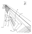
- Fig. 1 is a schematic perspective view of the apparatus for carrying out the method according to the invention.
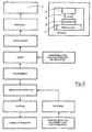
- Fig. 2 is a block diagram of the control assembly of the apparatus of Fig. 1.
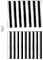
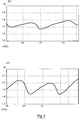
- Figs. 3 and 4 show the results of some characteristic tests of the invention.
- a wedge-shaped diamond point tool A machined with a determined angle is fixedly attached to a piezoelectric actuator P capable of carrying out a vertical micrometrically controlled displacement with a high repetition frequency.
- Diamond A is arranged with a horizontally aligned cutting edge S.
- Translation carriage C slides under tool A horizontally and transversally with respect to cutting edge S of the tool, said carriage carrying a metal substrate M having a surface B, on which the grating is cut, which has been formerly machined with optical finish and carefully positioned with respect to the edge of the tool.
- v the sliding speed of substrate M
- f the operation frequency of the piezoelectric actuator P.
- FIG. 2 A block diagram of the control assembly of the described apparatus is shown in Fig. 2.
- the invention allows a number of advantages to be achieved with respect to the already known techniques, among which a higher production speed which entails a considerable reduction of the cost of the end product, and a high capability of controlling the operating parameters with the result of a high flexibility as far as the type of the produced components is concerned.
- Fig. 3 shows two interference diagrams obtained by interferometer microscope and concerning the profile of gratings provided by the above-mentioned method
- Fig. 4 shows the profile of a grating detected by a mechanical high-resolution profilometer.
- the invention may be advantageously applied to the production of a large range of advanced optical components such as the diffraction gratings having varying spacing, which find application in the VUV spectroscopy and soft X-rays.
- advanced optical components such as the diffraction gratings having varying spacing, which find application in the VUV spectroscopy and soft X-rays.
- Such gratings can be particularly used in the field of the analysis of the synchrotron radiations and in the space applications as well.
Landscapes
- Physics & Mathematics (AREA)
- Engineering & Computer Science (AREA)
- Manufacturing & Machinery (AREA)
- General Physics & Mathematics (AREA)
- Optics & Photonics (AREA)
- Diffracting Gratings Or Hologram Optical Elements (AREA)
Claims (7)
- Procédé pour fabriquer des réseaux de diffraction, comprenant les étapes consistant à disposer le substrat, sur lequel les rainures de diffraction doivent être formées, sur des moyens de translation ayant une vitesse de translation commandée, et de former lesdites rainures au moyen d'un poinçonnage répétitif à l'aide d'un outil se déplaçant par rapport au substrat ;
caractérisé en ce que :
chaque étape de poinçonnage comprend le poinçonnage du substrat directement avec une arête en diamant en forme de coin dudit outil, tout en commandant la translation du substrat par rapport audit outil de poinçonnage, de manière à former une rainure lors de chaque course de l'outil sur la surface. - Procédé selon la revendication 1, caractérisé en ce que la vitesse de translation du substrat peut être modifiée par la translation du substrat par rapport à l'outil de poinçonnage de manière à créer des variations correspondantes de l'interstice entre les rainures de diffraction.
- Procédé selon les revendications 1 et 2, caractérisé en ce que l'outil de poinçonnage se déplace verticalement.
- Procédé selon les revendications 1 à 3, caractérisé en ce que le procédé consiste à équiper l'outil de poinçonnage d'une arête en diamant en forme de coin, cette arête étant disposée perpendiculairement à la direction de glissement du chariot portant le substrat.
- Procédé selon les revendications 1 à 4, caractérisé par l'orientation du substrat formé d'un corps solide et possédant une surface ayant un fini optique de telle sorte que ladite surface est tournée vers l'outil de poinçonnage.
- Dispositif pour la mise en oeuvre du procédé selon les revendications 1 et 2, dans lequel le dispositif comprend :a) un outil de poinçonnage pourvu d'une arête en diamant en forme de coin ;b) un actionneur piézoélectrique agencé de manière à entraíner l'outil de poinçonnage ;c) un ensemble électronique agencé de manière à commander l'actionneur ;d) un système de translation agencé de manière à porter le substrat ;e) des moyens de commande agencés de manière à commander la vitesse de translation du substrat, l'ensemble électronique et les moyens de commande étant disposés de manière à former une rainure lors de chaque course de l'outil sur la surface du substrat.
- Dispositif selon la revendication 6, caractérisé en ce que ledit ensemble électronique est un ensemble électro-optique.
Priority Applications (2)
| Application Number | Priority Date | Filing Date | Title |
|---|---|---|---|
| EP19940830166 EP0683404B1 (fr) | 1994-04-08 | 1994-04-08 | Méthode et appareil pour la production d'un réseau de diffraction pour usinage en cycle rapide |
| DE69421519T DE69421519D1 (de) | 1994-04-08 | 1994-04-08 | Verfahren und Gerät für die Herstellung von Beugungsgittern in schnellem Bearbeitungssystem |
Applications Claiming Priority (1)
| Application Number | Priority Date | Filing Date | Title |
|---|---|---|---|
| EP19940830166 EP0683404B1 (fr) | 1994-04-08 | 1994-04-08 | Méthode et appareil pour la production d'un réseau de diffraction pour usinage en cycle rapide |
Publications (2)
| Publication Number | Publication Date |
|---|---|
| EP0683404A1 EP0683404A1 (fr) | 1995-11-22 |
| EP0683404B1 true EP0683404B1 (fr) | 1999-11-03 |
Family
ID=8218420
Family Applications (1)
| Application Number | Title | Priority Date | Filing Date |
|---|---|---|---|
| EP19940830166 Expired - Lifetime EP0683404B1 (fr) | 1994-04-08 | 1994-04-08 | Méthode et appareil pour la production d'un réseau de diffraction pour usinage en cycle rapide |
Country Status (2)
| Country | Link |
|---|---|
| EP (1) | EP0683404B1 (fr) |
| DE (1) | DE69421519D1 (fr) |
Families Citing this family (6)
| Publication number | Priority date | Publication date | Assignee | Title |
|---|---|---|---|---|
| US6365073B1 (en) | 1998-07-21 | 2002-04-02 | Fabio De Sisti | Process for hot or cold-working prisms into a methacrylate optic conductor |
| CN101430394B (zh) * | 2007-11-05 | 2011-03-23 | 鸿富锦精密工业(深圳)有限公司 | 衍射光学元件 |
| CN109307900B (zh) * | 2018-11-26 | 2020-05-19 | 中国科学院长春光学精密机械与物理研究所 | 一种应用刻划机制作平面双闪耀光栅的方法 |
| CN109407192A (zh) * | 2018-11-26 | 2019-03-01 | 中国科学院长春光学精密机械与物理研究所 | 一种光栅刻划机刻线位置测量光路的调整方法及其系统 |
| CN110221371A (zh) * | 2019-07-10 | 2019-09-10 | 长春理工大学 | 一种采用单刀多刃进行机械刻划衍射光栅的方法 |
| CN114706152B (zh) * | 2022-03-15 | 2023-06-20 | 清华大学 | 图案化闪耀光栅的加工方法及系统 |
Family Cites Families (4)
| Publication number | Priority date | Publication date | Assignee | Title |
|---|---|---|---|---|
| CH664030A5 (de) * | 1984-07-06 | 1988-01-29 | Landis & Gyr Ag | Verfahren zur erzeugung eines makroskopischen flaechenmusters mit einer mikroskopischen struktur, insbesondere einer beugungsoptisch wirksamen struktur. |
| FR2632218A1 (fr) * | 1988-06-03 | 1989-12-08 | Lacoste Jean | Procede de sertissage de pieces metalliques utilisant le formage par pression magnetique et articles issus de la mise en oeuvre du procede |
| CA2029674C (fr) * | 1989-11-13 | 1997-06-10 | Keiji Sakai | Methode de fabrication d'un element de reseau de diffraction optique |
| EP0513755A3 (en) * | 1991-05-14 | 1994-05-18 | Canon Kk | A method for producing a diffraction grating |
-
1994
- 1994-04-08 DE DE69421519T patent/DE69421519D1/de not_active Expired - Lifetime
- 1994-04-08 EP EP19940830166 patent/EP0683404B1/fr not_active Expired - Lifetime
Also Published As
| Publication number | Publication date |
|---|---|
| EP0683404A1 (fr) | 1995-11-22 |
| DE69421519D1 (de) | 1999-12-09 |
Similar Documents
| Publication | Publication Date | Title |
|---|---|---|
| EP0169326B1 (fr) | Procédé et un dispositif de fabrication d'un motif de surface macroscopique à structure microscopique, en particulier d'une structure de diffraction optique | |
| DE69707653T2 (de) | Positionierungssystem mit mehreren werkzeugen | |
| EP1262315B1 (fr) | Méthode et dispositif de fabrication d'une plaque d'impression | |
| EP3036085B1 (fr) | Dispositif de fabrication d'objets tridimensionnels | |
| EP3165349B1 (fr) | Dispositif de fabrication d'objets tridimensionnels | |
| DE102016209555A1 (de) | Wafer-herstellungsverfahren | |
| EP0683404B1 (fr) | Méthode et appareil pour la production d'un réseau de diffraction pour usinage en cycle rapide | |
| JP2007050250A (ja) | 粒子治療設備の粒子線の粒子エネルギー分布拡大装置、粒子線監視及び粒子線調節ユニット及び方法 | |
| WO2000030802A1 (fr) | Dispositif et procede d'exploration de la surface d'un objet a l'aide d'un faisceau laser | |
| WO2010006589A4 (fr) | Système de gravure au laser pour la structuration de substrats pour modules solaires à couche mince | |
| DE102012011418A1 (de) | Stereolithographie- System | |
| DE102007037133A1 (de) | Verfahren und Vorrichtung zur Erzeugung einer Mehrzahl von Material-Schwächungsbereichen oder Perforierungen | |
| KR100850093B1 (ko) | 레이저 가공 장치 및 그 조정 방법 | |
| US7640776B2 (en) | Expanded metal machine | |
| EP3560686A1 (fr) | Machine d'usinage permettant la fabrication par couches de composants tridimensionnels | |
| KR100402937B1 (ko) | 전자빔을 사용한 구조화 에너지 전송방법 | |
| DE102013021961A1 (de) | Stereolithographie- System | |
| DE3886113T3 (de) | Präzises spannungsfreies Nachbehandlungsverfahren durch Radikalreaktionen. | |
| DE10316388B3 (de) | Verfahren und Vorrichtung zum Verlegen von Heiz-, Antennen- und/oder Dekor-Drähten auf einem zum Einbau in Verbundscheiben vorgesehenen Kunststoffsubstrat | |
| GB2180667A (en) | Manufacture of channel waveguides | |
| RU2108189C1 (ru) | Способ редуцирования ступенчатых многопрофильных валов | |
| EP4000773B1 (fr) | Dispositif de fabrication additive avec déflecteur acousto-optique et procédés associés | |
| DE29824994U1 (de) | Vorrichtung zum Herstellen eines Formkörpers mittels selektivem Laserschmelzen | |
| JP2007021526A (ja) | レーザ加工装置 | |
| DE102015118161A1 (de) | Vorrichtung zum Herstellen dreidimensionaler Objekte |
Legal Events
| Date | Code | Title | Description |
|---|---|---|---|
| PUAI | Public reference made under article 153(3) epc to a published international application that has entered the european phase |
Free format text: ORIGINAL CODE: 0009012 |
|
| AK | Designated contracting states |
Kind code of ref document: A1 Designated state(s): CH DE FR GB LI |
|
| 17P | Request for examination filed |
Effective date: 19960521 |
|
| 17Q | First examination report despatched |
Effective date: 19981120 |
|
| GRAG | Despatch of communication of intention to grant |
Free format text: ORIGINAL CODE: EPIDOS AGRA |
|
| GRAG | Despatch of communication of intention to grant |
Free format text: ORIGINAL CODE: EPIDOS AGRA |
|
| GRAH | Despatch of communication of intention to grant a patent |
Free format text: ORIGINAL CODE: EPIDOS IGRA |
|
| GRAH | Despatch of communication of intention to grant a patent |
Free format text: ORIGINAL CODE: EPIDOS IGRA |
|
| GRAA | (expected) grant |
Free format text: ORIGINAL CODE: 0009210 |
|
| AK | Designated contracting states |
Kind code of ref document: B1 Designated state(s): CH DE FR GB LI |
|
| PG25 | Lapsed in a contracting state [announced via postgrant information from national office to epo] |
Ref country code: LI Free format text: LAPSE BECAUSE OF FAILURE TO SUBMIT A TRANSLATION OF THE DESCRIPTION OR TO PAY THE FEE WITHIN THE PRESCRIBED TIME-LIMIT Effective date: 19991103 Ref country code: CH Free format text: LAPSE BECAUSE OF FAILURE TO SUBMIT A TRANSLATION OF THE DESCRIPTION OR TO PAY THE FEE WITHIN THE PRESCRIBED TIME-LIMIT Effective date: 19991103 |
|
| REG | Reference to a national code |
Ref country code: CH Ref legal event code: EP |
|
| REF | Corresponds to: |
Ref document number: 69421519 Country of ref document: DE Date of ref document: 19991209 |
|
| ET | Fr: translation filed | ||
| PG25 | Lapsed in a contracting state [announced via postgrant information from national office to epo] |
Ref country code: DE Free format text: LAPSE BECAUSE OF FAILURE TO SUBMIT A TRANSLATION OF THE DESCRIPTION OR TO PAY THE FEE WITHIN THE PRESCRIBED TIME-LIMIT Effective date: 20000204 |
|
| PG25 | Lapsed in a contracting state [announced via postgrant information from national office to epo] |
Ref country code: GB Free format text: LAPSE BECAUSE OF NON-PAYMENT OF DUE FEES Effective date: 20000408 |
|
| REG | Reference to a national code |
Ref country code: CH Ref legal event code: PL |
|
| PLBE | No opposition filed within time limit |
Free format text: ORIGINAL CODE: 0009261 |
|
| STAA | Information on the status of an ep patent application or granted ep patent |
Free format text: STATUS: NO OPPOSITION FILED WITHIN TIME LIMIT |
|
| 26N | No opposition filed | ||
| GBPC | Gb: european patent ceased through non-payment of renewal fee |
Effective date: 20000408 |
|
| PGFP | Annual fee paid to national office [announced via postgrant information from national office to epo] |
Ref country code: FR Payment date: 20030326 Year of fee payment: 10 |
|
| PG25 | Lapsed in a contracting state [announced via postgrant information from national office to epo] |
Ref country code: FR Free format text: LAPSE BECAUSE OF NON-PAYMENT OF DUE FEES Effective date: 20041231 |
|
| REG | Reference to a national code |
Ref country code: FR Ref legal event code: ST |