EP0683445B1 - Vanne électromagnétique avec moteur à force variable - Google Patents
Vanne électromagnétique avec moteur à force variable Download PDFInfo
- Publication number
- EP0683445B1 EP0683445B1 EP95101264A EP95101264A EP0683445B1 EP 0683445 B1 EP0683445 B1 EP 0683445B1 EP 95101264 A EP95101264 A EP 95101264A EP 95101264 A EP95101264 A EP 95101264A EP 0683445 B1 EP0683445 B1 EP 0683445B1
- Authority
- EP
- European Patent Office
- Prior art keywords
- armature
- valve
- assembly
- fluid
- inlet
- Prior art date
- Legal status (The legal status is an assumption and is not a legal conclusion. Google has not performed a legal analysis and makes no representation as to the accuracy of the status listed.)
- Expired - Lifetime
Links
Images

Classifications
-
- F—MECHANICAL ENGINEERING; LIGHTING; HEATING; WEAPONS; BLASTING
- F16—ENGINEERING ELEMENTS AND UNITS; GENERAL MEASURES FOR PRODUCING AND MAINTAINING EFFECTIVE FUNCTIONING OF MACHINES OR INSTALLATIONS; THERMAL INSULATION IN GENERAL
- F16K—VALVES; TAPS; COCKS; ACTUATING-FLOATS; DEVICES FOR VENTING OR AERATING
- F16K31/00—Actuating devices; Operating means; Releasing devices
- F16K31/02—Actuating devices; Operating means; Releasing devices electric; magnetic
- F16K31/06—Actuating devices; Operating means; Releasing devices electric; magnetic using a magnet, e.g. diaphragm valves, cutting off by means of a liquid
- F16K31/0603—Multiple-way valves
- F16K31/0624—Lift valves
-
- G—PHYSICS
- G05—CONTROLLING; REGULATING
- G05D—SYSTEMS FOR CONTROLLING OR REGULATING NON-ELECTRIC VARIABLES
- G05D16/00—Control of fluid pressure
- G05D16/20—Control of fluid pressure characterised by the use of electric means
- G05D16/2006—Control of fluid pressure characterised by the use of electric means with direct action of electric energy on controlling means
- G05D16/2013—Control of fluid pressure characterised by the use of electric means with direct action of electric energy on controlling means using throttling means as controlling means
- G05D16/2024—Control of fluid pressure characterised by the use of electric means with direct action of electric energy on controlling means using throttling means as controlling means the throttling means being a multiple-way valve
-
- Y—GENERAL TAGGING OF NEW TECHNOLOGICAL DEVELOPMENTS; GENERAL TAGGING OF CROSS-SECTIONAL TECHNOLOGIES SPANNING OVER SEVERAL SECTIONS OF THE IPC; TECHNICAL SUBJECTS COVERED BY FORMER USPC CROSS-REFERENCE ART COLLECTIONS [XRACs] AND DIGESTS
- Y10—TECHNICAL SUBJECTS COVERED BY FORMER USPC
- Y10T—TECHNICAL SUBJECTS COVERED BY FORMER US CLASSIFICATION
- Y10T137/00—Fluid handling
- Y10T137/2278—Pressure modulating relays or followers
Definitions
- the invention relates to a solenoid valve assembly for use in a fluid circuit to control the pressure in the fluid circuit in response to an electrical signal
- a solenoid sub-assembly having a movable armature adapted to axially translate with respect to an electromagnetic coil in response to the electrical signal being applied to the coil
- a valve sub-assembly including a valve body coupled to the solenoid sub-assembly and comprising a central bore, an exhaust port, an inlet and an outlet to said fluid circuit, and a valve member that is axially movable for controlling the pressure of fluid delivered from the inlet to the outlet, coupling means for coupling the valve member to the armature and a bearing means through which a portion of the coupling means extends, the bearing means adapted to support the coupling means for translational axial movement while concurrently providing fluid separation between the valve sub-assembly and the solenoid sub-assembly.
- Such a solenoid valve assembly is known from DE-A-3 818 109.
- This valve assembly has a pressure modulating section and a magnetic section, the pressure modulating section including a valve sleeve having an application port, an outlet port, a feedback port having a throttling passage, a drain port, and a spool being movable in the valve sleeve, the magnetic section including a coil assembly and a rod.
- the pressure modulating section including a valve sleeve having an application port, an outlet port, a feedback port having a throttling passage, a drain port, and a spool being movable in the valve sleeve
- the magnetic section including a coil assembly and a rod.
- a similar valve assembly is known from FR-A-2 696 018 which also comprises a movable armature which is arranged axially translatable before an electromagnetic coil and which is sealed against the spool of the valve section via a disk-shaped sealing element which cooperates with a central passage in a valve disk to provide a valve connection between,the inlet port and an exhaust port.
- solenoid-operated fluid control devices are used in a wide range of electrically controlled systems for controlling the pressure and/or flow rate of fluid discharged from a valve assembly in response to an electrical input signal supplied to a solenoid assembly.
- a valve sub-assembly and a solenoid sub-assembly are integrated into a unitized fluid control device, commonly referred to as a solenoid valve assembly.
- the solenoid sub-assembly has an armature which acts on, or is coupled to, a valve member in the valve sub-assembly.
- movement of the armature is responsive to the magnetic flux generated as a result of the electrical current applied to the electromagnetic windings of the solenoid sub-assembly.
- translational movement of the armature causes corresponding translational movement of the valve member for controlling the magnitude of the output pressure of fluid discharged from the valve sub-assembly.
- variable force solenoid valve assembly A variable force solenoid valve assembly
- VFS variable force solenoid valve assembly
- valve sub-assembly As in most hydraulic systems, the hydraulic fluid flowing through the valve sub-assembly is typically entrained with ferro-magnetic particles or shavings.
- fluid communication between the valve sub-assembly and the solenoid sub-assembly commonly results in the migration of these fluid-borne magnetic particles into the air gaps established between the armature and coil windings and/or other flux conducting components. Since some of the air gaps in solenoid sub-assemblies are calibrated after assembly to ensure precise accuracy, any subsequent contamination by magnetic particles can adversely affect the desired regulation characteristics of the output fluid pressure.
- the reluctance of the magnetic flux path controlling movement of the armature may vary significantly, thereby resulting in inaccurate correlations between the applied energization current and the expected output pressure.
- achieving isolation between the valve sub-assembly and the solenoid sub-assembly presents a number of significant design challenges.
- some solenoid valve assemblies attempt to isolate the electromagnetic components of the solenoid sub-assembly from the valving components of the valve sub-assembly by installing a flexible elastomeric diaphragm between the armature and the valve member for establishing a fluid-tight barrier.
- a flexible elastomeric diaphragm still necessitates the use of a separate guide bearing for guiding the axial translatory movement of the armature. Accordingly, there is a recognized need to develop a fluid-tight barrier or seal that effectively isolates the magnetic and fluid control components of the solenoid valve assembly and yet which overcomes the design and installation constraints typically associated with conventional diaphragm and bearing arrangements.
- a flexible bearing is installed between a movable valve member of the valve sub-assembly and a movable armature of the solenoid sub-assembly for supporting and guiding concurrent movement therebetween while concommitently maintaining a fluid-tight barrier seal.
- the armature is rigidly coupled to the valve member which cooperates with a valve seat formed at one end of the valve body which provides a flow restriction between the outlet port and a central bore in the valve body.
- the solenoid valve assembly has a pin member that couples the armature to the valve member and which passes through the flexible bearing.
- the flexible bearing includes a disc-like spring plate laminated between one or more layers of an elastomeric material to form a combined bearing/diaphragm seal.
- the combined bearing/diaphragm seal is mounted along its outer peripheral edge between a valve body of the valve sub-assembly and a tubular body of the solenoid sub-assembly.
- the combined bearing/diaphragm seal includes a central aperture surrounding the outer surface of the pin member in a fluid-tight manner.
- a fluid seal is effectuated between the working components of the valve sub-assembly and electromagnetic components of the solenoid sub-assembly in the solenoid valve assembly.
- the spring plate resiliently deflects in response to axial movement of the armature and pin member so as to function as a flexible bearing while the laminated layers of elastomeric material inhibit fluid within the valve sub-assembly from communicating with the electromagnetic components in the solenoid sub-assembly.
- This isolation prevents magnetically conductive particles entrained in the fluid from contaminating the air gap(s) and altering the reluctance of the electromagnetic flux circuit established within the solenoid sub-assembly.
- an improved variable force solenoid valve which is equipped with the combined bearing/diaphragm seal of the present invention.
- Use of the combined bearing/diaphragm seal is effective in maintaining the desired output pressure vs input current regulation characteristic over the entire service life of the variable force solenoid valve assembly.
- the valve sub-assembly is a bleed-type pressure control device having means for minimizing sensitivity to inlet pressure variations.
- the valve sub-assembly includes a spring-biased inlet compensator spool which is supported for axial movement within the valve body in response to inlet pressure variations. Such movement of the compensator spool results in a corresponding change in the amount of open area through the spool undercut, thereby establishing a "self-balanced" equilibrium state between the spring biasing exerted on the compensator spool and the inlet pressure.
- solenoid valve assembly 10 in accordance with this invention is shown in cross-section in FIG. 1, and is generally designated by reference numeral 10.
- solenoid valve assembly 10 is of a type used in a controller assembly for an automatic transmission, such as is disclosed in US-A-4,678,006.
- solenoid valve assembly 10 receives an electrical current signal from a remote electronic controller unit (not shown) for controllably regulating the fluid pressure within various flow channels of the automatic transmission.
- a remote electronic controller unit not shown
- Such pressure regulation permits finely tuned calibration of the rate of gear engagement or "shift feel", as described in greater detail in said US-A-4 678 006. Since the output fluid pressure is regulated in proportion to the magnitude of the electrical current signal, then solenoid valve assembly 10 is of the type generally referred to as a "variable force" solenoid valve assembly or "VFS".
- variable force solenoid valve assembly 10 is equipped with a unique combined bearing/diaphragm seal 12 for isolating the fluid controlling components from the electromagnetic solenoid components of variable force solenoid valve assembly 10.
- specific construction of variable force solenoid valve assembly 10 is merely exemplary and that combined bearing/diaphragm seal 12 may be used in any number of hydraulic or pneumatic fluid control valves, such as pulse-width modulated solenoids and ON/OFF solenoid-operated valves, as well as in any other application in which such fluid isolation is desired. Therefore, variable force solenoid valve assembly 10 is merely representative of but one exemplary application for combined bearing/diaphragm seal 12 of the present invention.
- variable force solenoid valve assembly 10 also includes a novel arrangement for minimizing sensitivity to inlet pressure fluctuations in a bleed-type pressure controlling device. While this arrangement will be detailed with greater specificity hereinafter, it is contemplated that the novel principles embodied therein can also be adapted for use in a plethora of electrically-modulated pressure control valves and the like.
- FIG. 1 provides a detailed illustration of the internal working components of variable force solenoid valve assembly 10.
- Variable force solenoid valve assembly 10 has two major sub-assemblies consisting of solenoid sub-assembly 14 and valve sub-assembly 16.
- solenoid sub-assembly 14 is enclosed by a cup-shaped tubular housing 18 having a generally closed end 20 with an annular groove 21 formed therein.
- a disc-like flux collector 22 having a central bore 24 and an annular groove 26 is fixed to the open end of housing 18.
- flux collector 22 is fixed to housing 18 via a plurality of circumferentially spaced tabs 28 which extend through corresponding apertures 30 formed in flux collector 22, with tabs 28 being subsequently rolled during an assembly staking operation.
- an electromagnetic coil assembly 32 comprised of a spool-shaped bobbin 34 on which an electrically-conductive coil 36 is wound.
- Bobbin 34 is made of an electrically non-conductive and non-magnetic material, such as nylon, and includes a central tubular segment 38 and a pair of radially extending end segments 40 and 42.
- raised annular projections 44 and 46 are respectively formed on end segments 40 and 42 and are shown seated with annular grooves 21 and 26 formed in closed end 20 of housing 18 and flux collector 22, respectively.
- the terminal ends of coil 36 are electrically connected to a pair of blade-type terminals (not shown). As is conventional, the blade-type terminals are adapted to be electrically connected to the remotely electronic controller unit via a suitable wiring harness (not shown).
- an adjustment plug 48 threadably engages a threaded central bore 50 formed in closed end 20 of housing 18.
- the external threads of a spring adjustment screw 52 threadably engage a central threaded bore 54 formed in adjustment plug 48.
- a coil spring 56 is shown to have a first end in engagement with a transverse spring seat surface 58 of spring adjustment screw 52 and a second end in engagement with a tapered shoulder 60 of an enlarged chamber 62 formed in one end of an armature 64.
- Armature 64 also includes a smaller longitudinal bore 66 which communicates with enlarged chamber 62.
- An elongated pin 68 is rigidly retained within longitudinal bore 66 of armature 64 via splines 70 to define an armature assembly 72.
- Pin 68 has a first end 74 which extend out of armature 64 and is coupled to a valve member of valve sub-assembly 16, as will be described.
- a second end 76 of pin 68 extends out of enlarged chamber 62 and is journally supported for longitudinal movement with armature assembly 72 via a guide bearing 78 that is mounted centrally within transverse surface 58 of spring adjustment screw 52.
- guide bearing 78 has a central bore 80 that is sized to journally support and surround the exterior surface of second end 76 of pin 68 to guide axial movement thereof while inhibiting excessive radial deflection for positioning and maintaining armature assembly 72 for translational movement along the common longitudinal axis of coil assembly 32.
- guide bearing 78 is adapted to maintain a relatively uniform radial clearance or "air gap" between the corresponding radial edge surfaces of armature 64 and adjustment plug 48 during longitudinal movement of armature assembly 72 relative to adjustment plug 48.
- a welch cap 81 is provided to enclose end 20 of housing 18.
- armature assembly 72 is shown to be positioned within a longitudinal bore 82 formed in tubular segment 38 of bobbin 34. More particularly, an elongated cylindrical portion 83 of armature 64 is coaxially aligned and retained within a central bore 84 formed in a tubular body member 86 such that armature assembly 72 can move longitudinally with respect thereto.
- Combined bearing/diaphragm seal 12 is adapted to guide longitudinal movement of first end 74 of pin 68 for maintaining a relatively uniform radial air gap between cylindrical portion 83 of armature 64 and tubular body 86.
- Tubular body member 86 is made from a magnetically conductive material and forms part of the electromagnetic flux circuit of solenoid sub-assembly 14, as will be described.
- a stepped end portion 88 of tubular body member 86 is press-fit within a bore 90 formed by an annular extension 92 of a valve body 94 associated with valve sub-assembly 16.
- flux collector 22 is rigidly secured (i.e., press-fit) to valve body 9 4 such that central bore 24 of flux collector 22 surrounds and engages an outer portion of valve body adjacent to extension 92.
- second end 76 of pin 68 is supported for translational movement via guide bearing 78 which is retained on spring adjustment screw 52.
- an armature stop ring 96 is press-fit into a recessed bore 97 formed in adjustment plug 48.
- Armature stop ring 96 is made of a magnetically non-conductive material and is sized and located to contact an end surface 98 of armature 64 so as to prevent radial surface 100 of armature extension 102 from contacting a facing shoulder surface 104 of adjustment plug 48.
- the distance between armature surface 100 and shoulder surface 104 defines an axial "air gap" that varies through a range established upon movement of armature assembly 72 relative to adjustment plug 48.
- a minimum current level (i.e., 0 A) is supplied to coil assembly 32 from the controller unit such that coil spring 56 is capable of forcibly displacing armature assembly 72 to the position shown in FIG. 1 for establishing a "maximum” axial air gap between surfaces 100 and 104.
- a maximum current level is supplied to coil assembly 32 for generating magnetic flux which exerts a maximum attractive force on armature 64 for moving armature assembly 72 toward adjustment plug 48 in opposition to the biasing of coil spring 56 to establish a "minimum” axial air gap between surfaces 100 and 104.
- coil assembly 32 is energized in order to induce a magnetic field which travels through a flux circuit or path comprising flux collector 22, valve body extension 92, tubular body member 86, armature body 64, adjustment plug 48, housing 18 and then back to flux collector 22.
- a flux circuit or path comprising flux collector 22, valve body extension 92, tubular body member 86, armature body 64, adjustment plug 48, housing 18 and then back to flux collector 22.
- each component associated with this flux circuit is made of a magnetic material.
- completion of the magnetic flux path results in a displacing or attractive force being exerted upon armature assembly 72 in a generally upward direction with respect to FIG. 1, in opposition to the biasing force normally exerted thereon by coil spring 56.
- armature assembly 72 translates within bobbin central bore 82 and tubular body member central bore 84, with its longitudinal orientation and radial clearances maintained by guide bearing 78 supporting second end 76 of pin 68 and combined bearing/diaphragm seal 12 supporting first end 74 of pin 68.
- a non-magnetic spacer ring 106 surrounds pin 68 and is located between a terminal end surface 108 of armature 64 and combined bearing/diaphragm seal 12 for the purpose of inhibiting contact therebetween, thereby preventing "shorting" of the magnetic flux path.
- variable force solenoid valve assembly 10 includes a mechanism for exerting an adjustable compliant loading on armature assembly 72 which opposes the attractive force generated through energization of coil assembly 32.
- armature assembly 72 which opposes the attractive force generated through energization of coil assembly 32.
- Adjustment plug 48 is made of magnetic material and provides means for variably adjusting the axial working air gap distance. More particularly, the axial air gap between radial surface 100 of armature 64 and radial surface 104 of adjustment plug 48 can be adjusted by varying the threaded position of adjustment plug 48 relative to closed end 20 of housing 18.
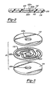
- combined bearing/diaphragm seal 12 is comprised of a relatively rigid, yet deflectably resilient spring plate 110 that is laminated between two layers 112 and 114 of a suitable elastomeric material.
- Combined bearing/diaphragm seal 12 is press-fit between the terminal end of end portion 88 of tubular body member 86 and a recessed shoulder surface 116 formed in annular extension 92 of valve body 94.
- combined bearing/diaphragm seal 12 is a "dual" function device which acts as a low friction, or frictionless, guide bearing for guiding movement of first end 74 of pin 68 as it translates therethrough.
- bearing/diaphragm seal 12 further functions to provide a "barrier" between a fluid chamber 118 of valve sub-assembly 16 and chamber 120 of solenoid sub-assembly 14 for inhibiting fluid communication therebetween.
- chamber 118 is filled with pressurized hydraulic fluid while chamber 120 is vented to atmospheric air.
- combined bearing/diaphragm seal 12 includes a thin disc-like spring plate 110 sandwiched between two layers 112 and 114 of an elastomeric material.
- the elastomeric layers are adapted to insulate spring plate 110 from the magnetic components associated with the solenoid flux path.
- Combined bearing/diaphragm seal 12 includes a central bore 122 through which pin member 68 passes and provides a bearing support for enabling pin member 68 to translate axially.
- spring plate 110 is preferably a flat circular metallic disc having a central bore 122a and a series of spiral cutouts 124 which enable spring plate 110 to deflect in both axial directions in correspondence with movement of pin member 68.
- cutouts 124 impart resilient flexibility in a direction perpendicular to the plane of flat spring plate 110 while maintaining rigidity in the general plane thereof.
- elastomeric layers 112 and 114 are preferably made from a low durometer material and are shown applied (i.e., glued) to both sides of spring plate 110.
- spring plate 110 may be coated (i.e., dipped, sprayed, etc.) with an elastomeric material.
- Elastomeric layers 112 and 114 enclose cutouts 124 and include bores 122b and 122c, respectively, which provide a fluid-tight seal relative to pin 68 during deflection of spring plate 110.
- elastomeric layers 112 and 114 provide a fluid seal across a number of potential fluid leakage paths, such as between cutouts 124, as well as around the outermost peripheral edge 126 of spring plate 110.
- spring plate 110 can be made of any suitable material (i.e., metallic or non-metallic) which provides the requisite rigidity and deflectable resiliency.
- the elastomeric layers could also be made of any material providing the requisite insulative and fluid isolating characteristics.
- variable force solenoid valve assembly 10 is operable to control the fluid pressure discharged from valve sub-assembly 16 in response to the electrical current signal applied to coil assembly 32. Such control is achieved by selectively regulating the outlet pressure by restricting fluid flow and venting or "bleeding" fluid to a sump.
- solenoid design it is also desirable to stabilize the input pressure characteristics of the valving to inhibit decay or attenuation of the effect of input pressure variations with time. Attenuation of such effects is provided, according to the preferred embodiment of this invention, through the utilization of an inlet pressure compensator that is designed to be "self-balancing" so as to minimize sensitivity of the regulated output pressure to fluctuations in the inlet pressure.
- Valve sub-assembly 16 is primarily comprised of valve body 94, an inlet compensator spool 130, a nozzle 132 and a plug 134.
- Inlet compensator spool 130 has a central axial passageway 136 and a pair of radial passageways 138 and 140 which communicate with inlet ports 142 and 144, respectively, of valve body 94.
- Inlet compensator spool 130 is positioned within a central bore 146 of valve body 94 so that it may translate therein.
- Plug 134 is press fit into an enlarged chamber 148 in valve body 94 and provides a fluid-tight lower stop for inlet compensator spool 130.
- a slip fit between inlet compensator spool 130 and central bore 146 provides a fluid seal therebetween to prevent direct fluid flow between inlet ports 142 and 144 and outlet ports 150 and 152 via central bore 146.
- a plurality of small pressure rings 154 are circumferentially disposed around the outer diameter of inlet compensator spool 136 and provide a more uniform distribution of forces resulting from the slip fit of inlet compensator spool 130 and central bore 146 of valve body 94.
- Inlet compensator spool 130 is downwardly biased, with respect to FIG. 1, by a coil spring 156 seated between a spring seat 158 formed at an end of inlet compensator spool 130 and a radial surface 160 formed in enlarged central bore 162 of nozzle 132.
- Inlet compensator spool 130 is adapted to compensate for fluctuations in the inlet pressure entering valve sub-assembly 16 at inlet ports 142 and 144 by varying the undercut or overlap between radial passages 138 and 140 and inlet ports 142 and 144, respectively.
- radial passages 138 and 140 provide fluid communication between inlet ports 142 and 144, respectively, and axial passage 136.
- fluid provided at inlet ports 142 and 144 flows through radial passages 138 and 140, respectively, and into axial passage 136.
- axial passage 136 communicates with output ports 150 and 152 via a flow restricting passage 164 and a fluid chamber 166 so that fluid from inlet ports 142 and 144 may ultimately be discharged at a desired output pressure through output ports 150 and 152.
- inlet compensator spool 130 is operable to stabilize the inlet fluid pressure of the fluid supplied to inlet ports 142 and 144 and which flows through radial passageways 138 and 140, respectively, into axial passageway 136, and subsequently into fluid chamber 166 via flow restrictor passage 164.
- a pressure gradient between passage 136 and fluid chamber 166 is established such that inlet spool compensator 130 experiences a lifting force in a direction opposing the biasing force exerted thereon by coil spring 156.
- inlet compensator spool 130 As the inlet fluid pressure increases, the lifting force experienced by inlet compensator spool 130 also increases and eventually overcomes the downwardly biasing force of coil spring 156 for moving inlet compensator spool 130 upward with respect to FIG. 1, thereby causing the overlap between inlet ports 142 and 144 and radial passages 138 and 140, respectively, to decrease. Accordingly, the decreased overlap causes a corresponding reduction in the fluid flow into axial passage 136. The reduced fluid flow decreases the fluid pressure within passageway 136 which, in turn, decreases the lifting force exerted on inlet spool compensator 130.
- inlet spool compensator 130 urges inlet spool compensator 130 to move in a downward direction, thereby increasing the overlap between inlet ports 142 and 144 and radial passages 138 and 140, respectively.
- This "self-balancing" system as effected by inlet compensator spool 130 and coil spring 156, provides a balanced inlet fluid pressure, thereby effectively reducing variations in the outlet fluid pressure as a result of inlet pressure fluctuations.
- nozzle 132 is shown press-fit into an enlarged portion 170 of central bore 146 of valve body 94.
- Nozzle 132 includes a raised valve seat 172 and a nozzle chamber 174 which communicates with fluid chamber 166.
- a poppet 176 is connected to first end 74 of pin member 68 and is adapted to move with armature assembly 72 for controlling fluid flow through nozzle chamber 174 to exhaust chamber 118.
- valve seat 172 is raised to maximize the pressure gradient between exhaust ports 178 and 180 and nozzle chamber 174 to effect a rapid outlet fluid pressure release.
- Poppet 176 further includes a raised annular flange 184 surrounding pin 68 which minimizes contact with the underside surface of combined bearing/diaphragm seal 12 for enabling greater flexibility thereof.
- poppet 176 is lifted off valve seat 172 in response to controlled upward movement of armature assembly 72 upon energization of coil assembly 32, thereby creating a fluid communication passageway between nozzle chamber 174 and exhaust chamber 118 so that the exhausted fluid may flow from exhaust ports 178 and 180 back to a low pressure fluid sump (not shown).
- Controlled modulation of the outlet pressure through outlet ports 150 and 152 is provided by selectively energizing coil assembly 32.
- a given level of current through coil 36 causes an induced magnetic flux which, in turn, creates a magnetic attractive force for urging armature assembly 72 in an upward direction in opposition to the biasing force imposed by coil spring 56 and as aided by the feedback pressure acting on poppet 176 in nozzle chamber 174.
- This action has the effect of increasing the opening between valve seat 172 and poppet 176.
- the resultant force causes armature assembly 72 to move in an upward direction, increasing the size of the fluid passageway between nozzle chamber 174 and exhaust chamber 118, thereby reducing the outlet fluid pressure at outlet ports 150 and 152.
Landscapes
- Engineering & Computer Science (AREA)
- Physics & Mathematics (AREA)
- General Engineering & Computer Science (AREA)
- Fluid Mechanics (AREA)
- Mechanical Engineering (AREA)
- General Physics & Mathematics (AREA)
- Automation & Control Theory (AREA)
- Magnetically Actuated Valves (AREA)
Claims (12)
- Ensemble de vanne électromagnétique pour utilisation dans un circuit fluidique afin de commander la pression dans le circuit fluidique en réponse à un signal électrique, comprenant :caractérisé en ce queun sous-ensemble électromagnétique (14) à électro-aimant à noyau plongeur (64) conçu pour effectuer un déplacement de translation axiale vis-à-vis d'un électro-aimant (32) en réponse audit signal électrique qui est appliqué audit électro-aimant (32) ;un sous-ensemble de vanne (16) incluant un corps de soupape (94) couplé audit sous-ensemble électromagnétique (14) et portant un orifice d'échappement (178, 180), un orifice d'admission (142, 144) et un orifice d'écoulement (150, 152) vers ledit circuit fluidique, et un ensemble de vanne (176) qui est mobile par déplacement axial pour commander la pression de fluide délivrée dudit orifice d'admission (142, 144) audit écoulement d'orifice (150, 152) ;un moyen de couplage (68) pour coupler ledit élément de vanne (176) audit électro-aimant (64) ; etun moyen porteur (12) à travers lequel une partie dudit moyen de couplage (68) s'étend, ledit moyen porteur (12) étant conçu pour supporter ledit moyen de couplage (68) pour déplacement axial de translation tout en fournissant simultanément une séparation fluidique entre ledit sous-ensemble de vanne (16) et ledit sous-ensemble électromagnétique (14);ledit électro-aimant (64) est agencé avec faculté de translation par déplacement axial à l'intérieur de l'électro-aimant à noyau plongeur (32) ;ledit corps de soupape (94) comprend, en outre, une tuyère de soupape (132) ayant un alésage central orienté coaxialement à un alésage central (146) dudit corps de soupape (94) et définit à une extrémité un siège de soupape (172) pour former une restriction d'écoulement entre ledit orifice d'écoulement (150, 152) et, ledit orifice d'échappement (178, 180) et à une extrémité opposée une chambre de tuyère (118) en communication avec ladite sortie (150, 152) ; et en ce queledit élément de vanne (176) coopère avec ledit siège de soupape (172) et est couplé de manière rigide par ledit moyen de couplage (68) audit électro-aimant (64) pour déplacement simultané avec celui-ci.
- Ensemble de vanne selon la revendication 1, caractérisé en ce que ledit moyen porteur est un joint d'étanchéité à palier/diaphragme combiné (12).
- Ensemble de vanne selon la revendication 2, caractérisé en ce que ledit joint d'étanchéité à palier/diaphragme combiné (12) comprend :une plaque de ressort plate (110) comportant un alésage (122a) permettant qu'une partie dudit électro-aimant (64) effectue une translation suivant une direction axiale traversante ; etun matériau d'étanchéité fluidique (112, 114) appliqué sur ladite plaque de ressort (110) pour procurer une isolation fluidique entre ledit alésage (122a) et ledit électro-aimant (64).
- Ensemble de vanne selon la revendication 2 ou 3, caractérisé en ce que ledit joint d'étanchéité à palier/diaphragme combiné (12) est conçu pour s'infléchir de manière élastique en réponse au déplacement en translation dudit électro-aimant (64).
- Ensemble de vanne selon la revendication 3 ou 4, caractérisé en ce que ledit matériau d'étanchéité fluidique (112, 114) est appliqué sur les deux faces de ladite plaque de ressort (110).
- Ensemble de vanne selon l'une quelconque des revendications 1 à 5, caractérisé en ce que ledit sous-ensemble électromagnétique (14) comprend en outre :une bobine d'alimentation (36) définissant un alésage longitudinal (82), ledit électro-aimant (64) étant disposé dans ledit alésage longitudinal (82) et conçu pour effectuer une translation en réponse à l'alimentation dudit électro-aimant (36) ;un moyen magnétique (48) pour définir un vide d'air fonctionnel à travers lequel des champs magnétiques sont transférés avec pour effet de générer une force d'attraction qui pousse ledit électro-aimant (64) à se déplacer vers ledit moyen magnétique (48) lorsque ledit électro-aimant (36) est alimenté ; etun moyen de ressort (56) disposé entre ledit moyen magnétique (48) et ledit électro-aimant (64) pour pousser ledit électro-aimant (64) en éloignement dudit moyen magnétique (48) lorsque ledit électro-aimant (36) est désalimenté.
- Ensemble de vanne selon la revendication 6, caractérisé en ce que ledit électro-aimant (64) comporte une première extrémité contre laquelle ledit moyen de ressort (56) agit et une seconde extrémité généralement fermée définissant un alésage central (66), ledit électro-aimant (64) incluant, en outre, une broche (70) comprenant une première extrémité (74) fixée de façon permanente à l'intérieur dudit alésage central (66) et une seconde extrémité (76) couplée audit élément de vanne (176), ledit joint d'étanchéité à palier/diaphragme combiné (12) étant situé entre ledit élément de vanne (176) et ladite seconde extrémité dudit électro-aimant (64).
- Ensemble de vanne selon l'une quelconque des revendications 6 ou 7, caractérisé en ce que ledit moyen magnétique comprend un moyen d'ajustement pour faire varier le vide d'air entre ledit électro-aimant (64) et ledit électro-aimant (32).
- Ensemble de vanne selon la revendication 8, caractérisé en ce que ledit moyen d'ajustement comprend un bouchon d'ajustement magnétique (48) fileté dans un alésage fileté central (50) d'un logement (18) entourant ledit sous-ensemble électromagnétique (14) pour faire varier le vide d'air minimal entre ledit électro-aimant (64) et ledit bouchon d'ajustement (48), ledit bouchon d'ajustement (48) ayant un alésage fileté central (54) conçu pour recevoir une vis d'ajustement de ressort (52), pour faire varier la force de sollicitation dudit moyen de ressort (56), et une bague d'arrêt annulaire (96) disposée à l'intérieur d'un alésage évidé (97) dudit bouchon d'ajustement (48) adjacent audit électro-aimant (64) pour empêcher l'engagement direct dudit électro-aimant (64) avec ledit bouchon d'ajustement (48).
- Ensemble de vanne selon l'une quelconque des revendications 1 à 9, caractérisé en ce que ledit corps de soupape (94) comprend en outre :une bobine de compensation d'admission (130) supportée pour déplacement de translation à l'intérieur dudit alésage central (162) dudit corps de soupape (94) et comportant un passage de fluide central (136) et des passages radiaux (138, 140) permettant une communication fluidique entre ledit orifice d'admission (142, 144) et ledit passage central (136), ledit passage central (136) communiquant également avec ladite partie de sortie (150, 152) ;un second moyen de ressort (156) en appui contre ladite tuyère de soupape (132) pour pousser ledit électro-aimant compensateur d'admission (130) dans une première direction ;avec pour effet que la pression d'admission est équilibrée de manière régulable en concordance avec la pression d'admission poussant ledit électro-aimant compensateur d'admission (130) dans une seconde direction contre la sollicitation exercée par ledit second moyen de ressort (156), avec pour effet de limiter la pression d'admission sur lesdits passages radiaux (138, 140) et de réduire ladite pression d'admission, ladite réduction de la pression d'admission amenant ledit second moyen de ressort (156) à pousser ledit électro-aimant compensateur d'admission (130) dans ladite première direction.
- Ensemble de vanne selon l'une quelconque des revendications 4 à 10, caractérisé en ce que ladite plaque de ressort flexible (110) est sensiblement plate et comporte des parties de découpe (124) permettant à ladite plaque (110) de se fléchir dans une direction essentiellement perpendiculaire à la direction de déplacement dudit électro-aimant (64).
- Ensemble de vanne selon l'une quelconque des revendications 3 à 11, caractérisé en ce que ledit matériau d'étanchéité fluidique (112, 114) est un matériau élastomère.
Applications Claiming Priority (2)
| Application Number | Priority Date | Filing Date | Title |
|---|---|---|---|
| US08/241,721 US5513832A (en) | 1994-04-22 | 1994-04-22 | Variable force solenoid valve |
| US241721 | 1994-04-22 |
Publications (2)
| Publication Number | Publication Date |
|---|---|
| EP0683445A1 EP0683445A1 (fr) | 1995-11-22 |
| EP0683445B1 true EP0683445B1 (fr) | 2002-05-22 |
Family
ID=22911895
Family Applications (1)
| Application Number | Title | Priority Date | Filing Date |
|---|---|---|---|
| EP95101264A Expired - Lifetime EP0683445B1 (fr) | 1994-04-22 | 1995-01-31 | Vanne électromagnétique avec moteur à force variable |
Country Status (4)
| Country | Link |
|---|---|
| US (1) | US5513832A (fr) |
| EP (1) | EP0683445B1 (fr) |
| CA (1) | CA2140838C (fr) |
| DE (1) | DE69526750T2 (fr) |
Families Citing this family (59)
| Publication number | Priority date | Publication date | Assignee | Title |
|---|---|---|---|---|
| US5611370A (en) * | 1994-11-10 | 1997-03-18 | Saturn Electronics & Engineering, Inc. | Proportional variable force solenoid control valve and transmission fluid control device |
| US6182942B1 (en) | 1995-12-01 | 2001-02-06 | Microhydraulics, Inc. | Actuator |
| US5996628A (en) * | 1996-01-16 | 1999-12-07 | Saturn Electronics & Engineering, Inc. | Proportional variable force solenoid control valve |
| US5630403A (en) * | 1996-06-13 | 1997-05-20 | Siemens Electric Limited | Force-balanced sonic flow emission control valve |
| US6019120A (en) * | 1996-12-19 | 2000-02-01 | Saturn Electronics & Engineering, Inc. | Single stage variable force solenoid pressure regulating valve |
| US5947442A (en) * | 1997-09-10 | 1999-09-07 | Cummins Engine Company, Inc. | Solenoid actuated valve assembly |
| US5957161A (en) * | 1998-11-05 | 1999-09-28 | Borg-Warner Automotive, Inc. | Long stroke balanced solenoid |
| US6029703A (en) * | 1998-12-18 | 2000-02-29 | Borg-Warner Automotive, Inc. | Pressure solenoid control valve with flux shunt |
| US6098741A (en) * | 1999-01-28 | 2000-08-08 | Eaton Corporation | Controlled torque steering system and method |
| DE19904901A1 (de) * | 1999-02-06 | 2000-08-10 | Zahnradfabrik Friedrichshafen | Proportional-Druckregelventil |
| US6269827B1 (en) | 1999-10-07 | 2001-08-07 | Eaton Corporation | Electrically operated pressure control valve |
| US6299130B1 (en) * | 1999-10-14 | 2001-10-09 | Siemens Canada Limited | EEGR valve with flexible bearing |
| US6341552B1 (en) | 2000-04-27 | 2002-01-29 | Eaton Corporation | Self-calibrating system and method for controlling a hydraulically operated device |
| US6386218B1 (en) * | 2000-08-17 | 2002-05-14 | Eaton Corporation | Solenoid operated valve assembly for variable bleed pressure proportional control |
| DE10146422A1 (de) | 2000-10-02 | 2002-05-08 | Caterpillar Inc | Zugelektromagnet mit hoher Kraft |
| DE10100422A1 (de) * | 2001-01-08 | 2002-07-11 | Bosch Gmbh Robert | Magnetventil zur Steuerung eines Einspritzventils einer Brennkraftmaschine |
| US20020162593A1 (en) * | 2001-05-03 | 2002-11-07 | Eaton Corporation | Electrically operated pressure control valve |
| US6443422B1 (en) | 2001-06-08 | 2002-09-03 | Eaton Corporation | Apparatus and method for adjusting an actuator on a real-time basis |
| DE60210306T2 (de) * | 2001-09-06 | 2006-11-30 | Invensys Sensor Systems | Druckregelventil mit einstellmerkmalen |
| US20030213927A1 (en) * | 2002-05-17 | 2003-11-20 | Hemsley Geoffrey V. | Modular fuel control valve |
| DE10343843A1 (de) * | 2003-09-23 | 2005-04-28 | Zahnradfabrik Friedrichshafen | Druckregelventil |
| US7055798B2 (en) * | 2004-02-06 | 2006-06-06 | Kojima Instruments Inc. | Proportional solenoid control valve |
| US7051993B2 (en) * | 2004-03-10 | 2006-05-30 | Eaton Corporation | Solenoid operated valve and method of making same |
| US6918571B1 (en) | 2004-11-18 | 2005-07-19 | Eaton Corporation | Solenoid operated valve assembly and method of making same |
| US20060272714A1 (en) * | 2005-06-03 | 2006-12-07 | Conrado Carrillo | Magnetic circuit design for linear actuator with small coil diameter |
| DE102005034939A1 (de) * | 2005-07-27 | 2007-02-01 | Schaeffler Kg | Elektromagnetische Stelleinheit |
| US20070056644A1 (en) * | 2005-09-13 | 2007-03-15 | Boddy Douglas E | Damper spool |
| DE102006038920B4 (de) | 2006-08-18 | 2013-01-31 | Pierburg Gmbh | Schwingungs- und pulsationsgedämpfter elektropneumatischer Wandler |
| JP4525736B2 (ja) * | 2007-11-09 | 2010-08-18 | 株式会社デンソー | リニアソレノイド |
| US20100059552A1 (en) * | 2008-09-10 | 2010-03-11 | Gpd Global, Inc. | Fluid dispensing valve with a spring plate |
| WO2010129826A2 (fr) * | 2009-05-07 | 2010-11-11 | Parker-Hannifin Corporation | Ensemble soupape de régulation à contrainte axiale et alignement automatique |
| JP2011057018A (ja) * | 2009-09-08 | 2011-03-24 | Yamaha Motor Co Ltd | 鞍乗型車両 |
| EP2312606B1 (fr) * | 2009-10-14 | 2013-02-27 | ABB Technology AG | Actionneur magnétique bistable pour un disjoncteur de tension moyenne |
| JP5711471B2 (ja) * | 2010-05-24 | 2015-04-30 | 株式会社城南製作所 | チャージポートリッドアセンブリー |
| US8627851B2 (en) * | 2010-06-14 | 2014-01-14 | Idex Health & Science Llc | Rebuildable micro-fluidic valve assembly |
| DE102010025175A1 (de) * | 2010-06-25 | 2011-12-29 | Pierburg Gmbh | Stufenlos regelbares Druckregelventil |
| US9133954B2 (en) * | 2010-09-06 | 2015-09-15 | Toyota Jidosha Kabushiki Kaisha | Electromagnetic linear valve |
| DE102010055033A1 (de) * | 2010-12-17 | 2012-06-21 | Pierburg Gmbh | Elektromagnetventil |
| JP5686201B2 (ja) * | 2011-11-04 | 2015-03-18 | トヨタ自動車株式会社 | 電磁式リニア弁 |
| KR102008824B1 (ko) | 2012-06-21 | 2019-08-08 | 보르그워너 인코퍼레이티드 | 침지형 솔레노이드 밸브 |
| DE202013012014U1 (de) * | 2013-03-27 | 2015-02-23 | Robert Bosch Gmbh | Betätigungsvorrichtung mit verdrehgesicherter Haltemutter |
| US9429242B2 (en) | 2013-04-19 | 2016-08-30 | Schaeffler Technologies AG & Co. KG | Dual poppet proportional solenoid control valve |
| US9377126B2 (en) * | 2013-07-22 | 2016-06-28 | Schaeffler Technologies AG & Co. KG | Control valve with integral pressure switch |
| JP6372995B2 (ja) * | 2013-11-11 | 2018-08-15 | 日本電産トーソク株式会社 | 電磁弁 |
| US9627121B2 (en) * | 2014-05-28 | 2017-04-18 | Flextronics Automotive, Inc. | Solenoid robust against misalignment of pole piece and flux sleeve |
| US9677523B2 (en) * | 2014-05-30 | 2017-06-13 | Cummins Inc. | Fuel injector including an injection control valve having an improved stator core |
| DE102014109517A1 (de) * | 2014-07-08 | 2016-01-14 | Svm Schultz Verwaltungs-Gmbh & Co. Kg | Magnetventil mit Mäanderfeder |
| DE102014109507A1 (de) * | 2014-07-08 | 2016-01-14 | SVM Schultz Verwaltungs- GmbH Co. KG | Elektromagnetventil |
| US11441694B2 (en) * | 2015-04-10 | 2022-09-13 | Viraraghavan S. Kumar | Solenoid controlled valve assembly including a poppet and diaphragm |
| US10088068B2 (en) | 2015-09-23 | 2018-10-02 | Hamilton Sundstrand Corporation | Flexures for flow regulation devices |
| US10240684B2 (en) * | 2016-06-23 | 2019-03-26 | Hamilton Sundstrand Corporation | Valve assembly having a manual override unit |
| US10287110B1 (en) * | 2016-12-05 | 2019-05-14 | James W. Sigmon | Compression-loaded plastic rotors |
| US10707001B2 (en) | 2017-10-30 | 2020-07-07 | Te Connectivity Corporation | Solenoid actuator with fast analog controlled economizer |
| US11027909B2 (en) | 2018-08-15 | 2021-06-08 | Gpcp Ip Holdings Llc | Automated flowable material dispensers and related methods for dispensing flowable material |
| JP7349669B2 (ja) * | 2018-12-07 | 2023-09-25 | 株式会社フジキン | 電磁弁、バルブ、流体制御装置、および電磁弁交換方法 |
| US12064063B2 (en) | 2019-09-23 | 2024-08-20 | Gpcp Ip Holdings Llc | Automated toilet seat cover dispenser |
| CN111652342B (zh) * | 2019-12-18 | 2023-09-01 | 中国船舶重工集团有限公司第七一0研究所 | 一种用于监测气枪激发的动磁式计数装置 |
| CN112483712B (zh) * | 2020-11-11 | 2023-02-03 | 北京宇航系统工程研究所 | 一种防卡滞高密封性能电磁阀 |
| US11248715B1 (en) * | 2020-12-22 | 2022-02-15 | Mac Valves, Inc. | Proportional solenoid valve |
Family Cites Families (28)
| Publication number | Priority date | Publication date | Assignee | Title |
|---|---|---|---|---|
| US1278254A (en) * | 1916-11-20 | 1918-09-10 | Bayard E Taylor | Door-latch. |
| US1958019A (en) * | 1932-11-01 | 1934-05-08 | James A Reasoner | Tank cap lock |
| US2535444A (en) * | 1948-09-17 | 1950-12-26 | Clarke E Miller | Door strike plate adjuster |
| FR2436865A1 (fr) * | 1978-09-22 | 1980-04-18 | Renault | Dispositif de condamnation a distance de trappe a essence |
| US4534375A (en) * | 1982-02-17 | 1985-08-13 | Borg-Warner Corporation | Proportional solenoid valve |
| US4715396A (en) * | 1981-10-16 | 1987-12-29 | Borg-Warner Corporation | Proportional solenoid valve |
| US4458930A (en) * | 1982-05-27 | 1984-07-10 | General Motors Corporation | Vehicle body closure arrangement |
| US4540154A (en) * | 1982-06-28 | 1985-09-10 | Imperial Clevite Inc. | Solenoid valve |
| DE3227229A1 (de) * | 1982-07-21 | 1984-01-26 | Robert Bosch Gmbh, 7000 Stuttgart | Druckregler |
| US4522371A (en) * | 1983-06-20 | 1985-06-11 | Borg-Warner Corporation | Proportional solenoid valve |
| US5045455A (en) * | 1984-01-12 | 1991-09-03 | Chiron Corporation | Factor VIII:C cDNA cloning and expression |
| US4635683A (en) * | 1985-10-03 | 1987-01-13 | Ford Motor Company | Variable force solenoid |
| DE3702903A1 (de) * | 1987-01-31 | 1988-08-11 | Porsche Ag | Klappe zum verschliessen einer karosseriemulde |
| US4838313A (en) * | 1987-05-28 | 1989-06-13 | Aisin Aw Co., Ltd. | Solenoid-operated pressure control valve |
| US4988074A (en) * | 1988-05-17 | 1991-01-29 | Hi-Ram, Inc. | Proportional variable force solenoid control valve |
| US4917418A (en) * | 1988-12-12 | 1990-04-17 | Babcock Industries Inc. | Fuel filler door release system |
| US4947893A (en) * | 1989-02-28 | 1990-08-14 | Lectron Products, Inc. | Variable force solenoid pressure regulator for electronic transmission controller |
| US4971370A (en) * | 1989-04-25 | 1990-11-20 | Lectron Products, Inc. | Self-releasing deck lid latch |
| US4951637A (en) * | 1989-06-29 | 1990-08-28 | Siemens-Bendix Automotive Electronics Limited | Purge flow regulator |
| US4995369A (en) * | 1989-12-18 | 1991-02-26 | Siemens-Bendix Automotive Electronics Limited | Regulated flow canister purge system |
| US5050568A (en) * | 1990-03-08 | 1991-09-24 | Siemens Automotive Limited | Regulated flow canister purge system |
| DE4016990A1 (de) * | 1990-01-20 | 1991-07-25 | Bosch Gmbh Robert | Elektromagnetisch betaetigbares ventil |
| US5115785A (en) * | 1990-05-01 | 1992-05-26 | Siemens Automotive Limited | Carbon canister purge system |
| US5113837A (en) * | 1990-06-25 | 1992-05-19 | Mike Baitel | Air induction control device |
| US5069188A (en) * | 1991-02-15 | 1991-12-03 | Siemens Automotive Limited | Regulated canister purge solenoid valve having improved purging at engine idle |
| US5083546A (en) * | 1991-02-19 | 1992-01-28 | Lectron Products, Inc. | Two-stage high flow purge valve |
| US5183022A (en) * | 1991-07-16 | 1993-02-02 | Siemens Automotive Limited | Multi-slope canister purge solenoid valve |
| DE4231998A1 (de) * | 1992-09-24 | 1994-03-31 | Bosch Gmbh Robert | Elektromagnetisch betätigbares Druckregelventil |
-
1994
- 1994-04-22 US US08/241,721 patent/US5513832A/en not_active Expired - Lifetime
-
1995
- 1995-01-23 CA CA002140838A patent/CA2140838C/fr not_active Expired - Fee Related
- 1995-01-31 EP EP95101264A patent/EP0683445B1/fr not_active Expired - Lifetime
- 1995-01-31 DE DE69526750T patent/DE69526750T2/de not_active Expired - Fee Related
Also Published As
| Publication number | Publication date |
|---|---|
| CA2140838C (fr) | 1999-05-04 |
| EP0683445A1 (fr) | 1995-11-22 |
| CA2140838A1 (fr) | 1995-10-23 |
| DE69526750D1 (de) | 2002-06-27 |
| DE69526750T2 (de) | 2002-09-05 |
| US5513832A (en) | 1996-05-07 |
Similar Documents
| Publication | Publication Date | Title |
|---|---|---|
| US5513832A (en) | Variable force solenoid valve | |
| EP0688989B1 (fr) | Régulateur de pression modulé électriquement avec un solénoide à variation de force | |
| US5853028A (en) | Variable force solenoid operated valve assembly with dampener | |
| US4947893A (en) | Variable force solenoid pressure regulator for electronic transmission controller | |
| US5571248A (en) | Pressure regulator | |
| US6220569B1 (en) | Electrically controlled proportional valve | |
| EP0451347B1 (fr) | Régulateur de pression pour un écoulement dans un bypass | |
| US4452424A (en) | Electromagnetic linear control valve | |
| US4932439A (en) | Solenoid actuated three-way valve | |
| GB2256288A (en) | Solenoid operated pressure regulating valve | |
| US5282604A (en) | Solenoid operated pressure regulating valve | |
| US5218996A (en) | Three-way three-position solenoid valve | |
| US5538026A (en) | Pilot-operated proportional control valve | |
| US5289841A (en) | Solenoid valve and valve calibrating method | |
| US6899313B2 (en) | Magnetic actuator and method | |
| US4251051A (en) | Solenoid structure having a relatively unrestrained generally flat armature member | |
| MXPA95005076A (es) | Valvula de control de flujo direccional. | |
| AU2895484A (en) | Proportional solenoid valve | |
| EP0267162B1 (fr) | Electrovannes régulant la pression, notamment pour circuits à haute pression pour systèmes d'injection de machines à combustion interne | |
| EP0795706B1 (fr) | Obturateur universel à électro-aimant | |
| US4953825A (en) | Electro-magnetic proportional flow control valve | |
| EP0254483B1 (fr) | Régulateurs de pression commandés par électro-aimant | |
| KR100476246B1 (ko) | 비례압력 제어밸브 | |
| EP0385286B1 (fr) | Régulateur de pression ayant un solénoide à force variable pour la commande électronique d'une transmission | |
| CA2219030C (fr) | Robinet pressostatique a commande electrique |
Legal Events
| Date | Code | Title | Description |
|---|---|---|---|
| PUAI | Public reference made under article 153(3) epc to a published international application that has entered the european phase |
Free format text: ORIGINAL CODE: 0009012 |
|
| AK | Designated contracting states |
Kind code of ref document: A1 Designated state(s): DE FR GB |
|
| 17P | Request for examination filed |
Effective date: 19960510 |
|
| 17Q | First examination report despatched |
Effective date: 19980715 |
|
| GRAG | Despatch of communication of intention to grant |
Free format text: ORIGINAL CODE: EPIDOS AGRA |
|
| GRAG | Despatch of communication of intention to grant |
Free format text: ORIGINAL CODE: EPIDOS AGRA |
|
| GRAH | Despatch of communication of intention to grant a patent |
Free format text: ORIGINAL CODE: EPIDOS IGRA |
|
| GRAH | Despatch of communication of intention to grant a patent |
Free format text: ORIGINAL CODE: EPIDOS IGRA |
|
| GRAA | (expected) grant |
Free format text: ORIGINAL CODE: 0009210 |
|
| REG | Reference to a national code |
Ref country code: GB Ref legal event code: FG4D |
|
| REF | Corresponds to: |
Ref document number: 69526750 Country of ref document: DE Date of ref document: 20020627 |
|
| ET | Fr: translation filed | ||
| PLBE | No opposition filed within time limit |
Free format text: ORIGINAL CODE: 0009261 |
|
| STAA | Information on the status of an ep patent application or granted ep patent |
Free format text: STATUS: NO OPPOSITION FILED WITHIN TIME LIMIT |
|
| 26N | No opposition filed |
Effective date: 20030225 |
|
| PGFP | Annual fee paid to national office [announced via postgrant information from national office to epo] |
Ref country code: DE Payment date: 20090130 Year of fee payment: 15 |
|
| PGFP | Annual fee paid to national office [announced via postgrant information from national office to epo] |
Ref country code: GB Payment date: 20081211 Year of fee payment: 15 |
|
| PGFP | Annual fee paid to national office [announced via postgrant information from national office to epo] |
Ref country code: FR Payment date: 20090106 Year of fee payment: 15 |
|
| GBPC | Gb: european patent ceased through non-payment of renewal fee |
Effective date: 20100131 |
|
| REG | Reference to a national code |
Ref country code: FR Ref legal event code: ST Effective date: 20100930 |
|
| PG25 | Lapsed in a contracting state [announced via postgrant information from national office to epo] |
Ref country code: FR Free format text: LAPSE BECAUSE OF NON-PAYMENT OF DUE FEES Effective date: 20100201 |
|
| PG25 | Lapsed in a contracting state [announced via postgrant information from national office to epo] |
Ref country code: DE Free format text: LAPSE BECAUSE OF NON-PAYMENT OF DUE FEES Effective date: 20100803 |
|
| PG25 | Lapsed in a contracting state [announced via postgrant information from national office to epo] |
Ref country code: GB Free format text: LAPSE BECAUSE OF NON-PAYMENT OF DUE FEES Effective date: 20100131 |