EP0683545B1 - Kabelverschraubungen zum Anschliessen von Kabeln und Rohren - Google Patents
Kabelverschraubungen zum Anschliessen von Kabeln und Rohren Download PDFInfo
- Publication number
- EP0683545B1 EP0683545B1 EP19950303253 EP95303253A EP0683545B1 EP 0683545 B1 EP0683545 B1 EP 0683545B1 EP 19950303253 EP19950303253 EP 19950303253 EP 95303253 A EP95303253 A EP 95303253A EP 0683545 B1 EP0683545 B1 EP 0683545B1
- Authority
- EP
- European Patent Office
- Prior art keywords
- pipe
- cable
- gland
- opening
- earthing ring
- Prior art date
- Legal status (The legal status is an assumption and is not a legal conclusion. Google has not performed a legal analysis and makes no representation as to the accuracy of the status listed.)
- Expired - Lifetime
Links
- 210000004907 gland Anatomy 0.000 title claims abstract description 50
- 238000009413 insulation Methods 0.000 claims abstract description 11
- 239000012777 electrically insulating material Substances 0.000 claims description 4
- 238000007789 sealing Methods 0.000 claims description 4
- 230000006835 compression Effects 0.000 claims description 3
- 238000007906 compression Methods 0.000 claims description 3
- 238000000034 method Methods 0.000 claims description 2
- 239000012858 resilient material Substances 0.000 claims description 2
- 239000004020 conductor Substances 0.000 description 8
- XAGFODPZIPBFFR-UHFFFAOYSA-N aluminium Chemical compound [Al] XAGFODPZIPBFFR-UHFFFAOYSA-N 0.000 description 1
- 229910052782 aluminium Inorganic materials 0.000 description 1
- 239000004411 aluminium Substances 0.000 description 1
- 230000000295 complement effect Effects 0.000 description 1
- 239000002131 composite material Substances 0.000 description 1
- 239000000835 fiber Substances 0.000 description 1
- 239000004033 plastic Substances 0.000 description 1
- 229920003023 plastic Polymers 0.000 description 1
Images

Classifications
-
- H—ELECTRICITY
- H01—ELECTRIC ELEMENTS
- H01R—ELECTRICALLY-CONDUCTIVE CONNECTIONS; STRUCTURAL ASSOCIATIONS OF A PLURALITY OF MUTUALLY-INSULATED ELECTRICAL CONNECTING ELEMENTS; COUPLING DEVICES; CURRENT COLLECTORS
- H01R4/00—Electrically-conductive connections between two or more conductive members in direct contact, i.e. touching one another; Means for effecting or maintaining such contact; Electrically-conductive connections having two or more spaced connecting locations for conductors and using contact members penetrating insulation
- H01R4/58—Electrically-conductive connections between two or more conductive members in direct contact, i.e. touching one another; Means for effecting or maintaining such contact; Electrically-conductive connections having two or more spaced connecting locations for conductors and using contact members penetrating insulation characterised by the form or material of the contacting members
- H01R4/64—Connections between or with conductive parts having primarily a non-electric function, e.g. frame, casing, rail
- H01R4/646—Connections between or with conductive parts having primarily a non-electric function, e.g. frame, casing, rail for cables or flexible cylindrical bodies
-
- F—MECHANICAL ENGINEERING; LIGHTING; HEATING; WEAPONS; BLASTING
- F16—ENGINEERING ELEMENTS AND UNITS; GENERAL MEASURES FOR PRODUCING AND MAINTAINING EFFECTIVE FUNCTIONING OF MACHINES OR INSTALLATIONS; THERMAL INSULATION IN GENERAL
- F16L—PIPES; JOINTS OR FITTINGS FOR PIPES; SUPPORTS FOR PIPES, CABLES OR PROTECTIVE TUBING; MEANS FOR THERMAL INSULATION IN GENERAL
- F16L25/00—Construction or details of pipe joints not provided for in, or of interest apart from, groups F16L13/00 - F16L23/00
- F16L25/01—Construction or details of pipe joints not provided for in, or of interest apart from, groups F16L13/00 - F16L23/00 specially adapted for realising electrical conduction between the two pipe ends of the joint or between parts thereof
-
- H—ELECTRICITY
- H01—ELECTRIC ELEMENTS
- H01R—ELECTRICALLY-CONDUCTIVE CONNECTIONS; STRUCTURAL ASSOCIATIONS OF A PLURALITY OF MUTUALLY-INSULATED ELECTRICAL CONNECTING ELEMENTS; COUPLING DEVICES; CURRENT COLLECTORS
- H01R4/00—Electrically-conductive connections between two or more conductive members in direct contact, i.e. touching one another; Means for effecting or maintaining such contact; Electrically-conductive connections having two or more spaced connecting locations for conductors and using contact members penetrating insulation
- H01R4/58—Electrically-conductive connections between two or more conductive members in direct contact, i.e. touching one another; Means for effecting or maintaining such contact; Electrically-conductive connections having two or more spaced connecting locations for conductors and using contact members penetrating insulation characterised by the form or material of the contacting members
- H01R4/60—Connections between or with tubular conductors
Definitions
- This invention relates to glands for terminating cables and pipes.
- the invention has particular application to terminations where good earth continuity is required between electrically conductive parts of the gland and the cable or pipe.
- the cable or pipe has an electrically conductive sleeve covered by an outer sheath of electrically insulating material that is received in an electrically conductive body of the gland.
- an outer sheath of electrically insulating material that is received in an electrically conductive body of the gland.
- DE-B-1615624 (& GB 1128428) discloses a connector for coaxial cable having a continuity member with resilient contact fingers extending from one end of a tubular body.
- the outer insulation of the cable is removed to expose the outer conductor, and the tubular body inserted under the outer conductor with the contact fingers extending back over the outer conductor.
- a cylindrical ferrule is then fitted over the contact fingers to force the contact fingers inwards to penetrate the outer conductor and the ferrule crimped to secure the assembly and sandwich the outer conductor between the tubular body and the contact fingers of the continuity member.
- FR-B-1312525 discloses a connector for coaxial cable having a continuity member with resilient contact fingers extending from the inner periphery of an annular collar. To assemble the connector, the contact fingers are manually tightened to pierce the outer insulation of the cable and contact the outer conductor. A conical socket is then slid over the contact arms up to the collar and is secured by screwing a sleeve nut on a threaded socket.
- a gland for terminating cables or pipes having an electrically conductive sleeve covered by an outer sheath of electrically insulating material comprising an electrically conductive gland body having an axial opening at one end for receiving the cable or pipe, and an electrically conductive earthing ring for reception in the opening to provide an earth connection between the gland body and the conductive sleeve of the cable or pipe, the earthing ring having at least one contact finger with an inwardly directed projection deflectable inwardly to pierce the outer sheath and contact the sleeve to establish the earth connection characterised in that, in use the earthing ring is a push fit in the opening with the cable or pipe, and the at least one contact finger is deflected inwardly by engagement with a tapered entry portion of the opening causing the projection to pierce the outer sheath and contact the conductive sleeve of the cable or pipe.
- the main advantage of the invention is that earth continuity between electrically conductive parts of the gland and cable or pipe is established automatically without removing the outer sheath by push fit of the earthing ring in the opening with the cable or pipe during assembly.
- the earthing ring preferably has a plurality of circumferentially spaced contact fingers and may comprise a flat washer with the or each contact finger extending from the periphery of the washer.
- the or each contact finger is arranged to extend axially and radially outwards of the washer in an undeformed free state of the earthing ring prior to being inserted in the opening.
- the gland body preferably has an internal shoulder for axially locating the earthing ring in the opening.
- the shoulder may be provided by a counterbore in the gland body with the earthing ring arranged to bear against the shoulder with the or each contact finger being a close fit with the cable or pipe in the counterbore in the assembled gland.
- the sealing means may comprise an annular seal of resilient material preferably positioned between the gland body and a seal nut so as to be compressed inwardly to engage the outer sheath by threaded engagement of the seal nut with the gland body.
- the seal may be arranged to bear against the end of the gland body or the tapered entry portion of the opening, and means is preferably provided to control compression of the seal on tightening the seal nut.
- a method of terminating a cable or pipe comprises axially locating an earthing ring having at least one contact finger on the cable or pipe with said at least one contact finger extending axially and radially outwardly of the cable or pipe, presenting a gland body to the cable or pipe with the earthing ring located thereon, inserting the cable or pipe together with the earthing ring into an opening in the gland body so that the at least one contact finger engages a tapered entry portion of the opening and is deflected inwardly causing an inwardly directed projection of the at least one contact finger to pierce an outer insulation sheath of the cable or pipe and contact an inner conductive sleeve of the cable or pipe to establish electrical continuity between the inner sleeve and the gland body.
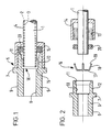
- a composite pipe 1 for one or more conductors such as electric cable or fibre optic cable comprises an electrically conductive sleeve 2 sandwiched between inner and outer electrically insulating sheaths 3 and 4 respectively.
- the sleeve 2 is an aluminium tube and the sheaths 3,4 are made of non-conducting plastics having appropriate properties for the intended application.
- An earth continuity termination for the pipe 1 is provided by a gland 5 having an electrically conductive entry body 6 formed with an external hexagonal flange 7 for engagement by a spanner or like tool to rotate the entry body 6.
- One end of the body 6 has a cylindrical bore 8 and an external thread 9 for securing the entry body 6 to an enclosure such as a junction box or other electrical equipment (not shown) to which the conductor(s) extending through the pipe 1 are connected in known manner.
- an enclosure such as a junction box or other electrical equipment (not shown) to which the conductor(s) extending through the pipe 1 are connected in known manner.
- the other end of the body 6 has a coaxial counterbore 10 with a tapered portion 11 of frusto-conical shape at the outer end and an external thread 12 for threaded engagement with a complementary internal thread 13 of a seal nut 14.
- the counterbore 10 terminates at the inner end in an internal shoulder 15 providing a seating for an electrically conductive earthing ring 16.
- the ring 16 comprises a flat annular washer 17 sized to fit within the counterbore 10 and provided with a plurality of circumferentially spaced deflectable cantilever contact fingers 18.
- the contact fingers 18 extend axially and radially outwards from the periphery of the washer 17 in the undeformed free state of the ring 16 and terminate in radially inwardly directed spikes 19.
- the seal nut 14 and a resilient annular seal 20 of U-shape in axial section are slipped over the end of the pipe 1.
- the earthing ring 16 is then positioned with the washer 17 seated against the end of the pipe 1 to axially locate the earthing ring 16 and the contact fingers 18 surrounding and spaced from the outer sheath 4.
- the end of the pipe 1 and earthing ring 16 are then pushed into the counterbore 10 of the entry body 6 until the washer 17 locates against the shoulder 15.
- the contact fingers 18 are compressed radially inwards by engagement with frusto-conical entry portion 11 causing the spikes 19 to pierce the outer sheath 4 and contact the sleeve 2.
- the pipe 1 and deformed fingers 18 are a close fit in the counterbore 10 when pushed fully home thereby ensuring good earth continuity between the sleeve 2 and entry body 6 through the ring 16.
- the termination is completed by bringing the seal nut 14 into threaded engagement with the entry body 6.
- the seal 20 is compressed onto the outer sheath 4 of the pipe 1 to provide a fluid-tight seal and strong grip to prevent the pipe 1 being pulled out of the entry body 6.
- a constant compression of the seal 20 is obtained by tightening the seal nut 14 against the flange 7 of the entry body 6.
- FIG. 4 shows a second embodiment in which like reference numerals are used to indicate parts corresponding to the first embodiment above-described.
- an O-ring 20 is compressed by engagement with the frusto-conical entry portion 11 on tightening the seal nut 14 to provide a fluid-tight seal and strong grip to prevent the pipe 1 being pulled out of the entry body 6.
- the earthing ring 16 ensures that good earth continuity is obtained between the sleeve 2 and entry body 6 on assembly without removing the outer insulation sheath 4 of the pipe 1. Furthermore, by arranging the earthing ring to be a push fit on inserting the cable or pipe 1 with contact fingers 18 that are deflected to pierce the outer insulation sheath 4 of the cable or pipe 1, the required earth continuity is achieved independently of and does not rely on threaded engagement of the seal nut 14 with the entry body 6.
- the invention is not limited to terminations for pipes and may be applied to terminations for electric cables in which an outer insulation sheath covers an electrically conductive sleeve such as wire armour or braid.
Landscapes
- Engineering & Computer Science (AREA)
- General Engineering & Computer Science (AREA)
- Mechanical Engineering (AREA)
- Communication Cables (AREA)
- Installation Of Indoor Wiring (AREA)
- Waveguide Aerials (AREA)
- Laying Of Electric Cables Or Lines Outside (AREA)
- Insulating Bodies (AREA)
Claims (10)
- Kabelverschraubung (5) zum Anschliessen von einem elektrisch leitenden Mantel (2), der durch eine Außenhülle (4) aus elektrischem Isolationsmaterial bedeckt ist, aufweisenden Kabeln oder Rohren (1), mit einem elektrischen leitenden Verschraubungsgehäuse (6), welches eine axiale Öffnung (10) an einem Ende zur Aufnahme des Kabels oder Rohres (1) und einen elektrisch leitenden Erdungsring (16) zur Aufnahme in der Öffnung (10) zur Herstellung einer Erdverbindung zwischen dem Verschraubungsgehäuse (6) und dem Kabel oder Rohr (1) aufweist, wobei der Erdungsring (16) mindestens einen Kontaktfinger (18) mit einem nach innen gerichteten Vorsprung (19) aufweist, welcher nach innen auslenkbar ist, um die Aussenhülle (4) zu durchstossen und den Mantel (2) zur Herstellung der Erdverbindung zu berühren, dadurch gekennzeichnet, dass bei der Verwendung der Erdungsring (16) mit dem Kabel oder Rohr (1) in der Öffnung (10) in Schiebepassung befindlich ist, und dass der mindestens eine Kontaktfinger (18) durch Eingriff mit einem sich verjüngenden Eingangsabschnitt (11) der Öffnung (10) nach innen ausgelenkt wird, wodurch der Vorsprung (19) die Aussenhülle (4) durchstösst und den leitenden Mantel (2) des Kabels oder Rohres (1) berührt.
- Kabelverschraubung nach Anspruch 1, dadurch gekennzeichnet, dass der Erdungsring (16) eine Vielzahl von am Umfang in Abständen angeordneten Kontaktfingern (18) aufweist.
- Kabelverschraubung nach Anspruch 1 oder 2, dadurch gekennzeichnet, dass der Erdungsring (16) eine flache Scheibe (17) aufweist, wobei sich der oder jeder der Kontaktfinger (18) vom Umfang der Scheibe (17) ausgeht.
- Kabelverschraubung nach Anspruch 3, dadurch gekennzeichnet, dass der oder jeder Kontaktfinger (18) derart angeordnet ist, dass er sich axial und radial von der Scheibe (17) in einem nicht deformierten freien Zustand des Erdungsringes (16) nach aussen erstreckt, ehe er in die Öffnung (10) eingesetzt wird.
- Kabelverschraubung nach einem der vorstehenden Ansprüche, dadurch gekennzeichnet, dass das Verschraubungsgehäuse (6) eine Innenschulter (15) für die axiale Festlegung des Erdungsringes (16) in der Öffnung (10) aufweist.
- Kabelverschraubung nach Anspruch 5, dadurch gekennzeichnet, dass die Schulter (15) mit einer Gegenbohrung (10) in dem Verschraubungsgehäuse (6) versehen ist, und dass der Erdungsring (16) an der Schulter (15) anliegt, wobei der oder jeder der Kontaktfinger (18) in dichter Passung mit einem Kabel oder Rohr in der Gegenbohrung (10) in der zusammengefügten Verschraubung (5) steht.
- Kabelverschraubung nach einem der vorstehenden Ansprüche, dadurch gekennzeichnet, dass eine Einrichtung (20) vorgesehen ist, um einen dichtenden Eingriff mit der Aussenhülle (4) des Kabels oder Rohres (1) herzustellen.
- Kabelverschraubung nach Anspruch 7, dadurch gekennzeichnet, dass die Dichteinrichtung (20) eine ringförmige Dichtung (20) aus nachgiebigem Material umfasst, welches zum Eingriff mit der Aussenhülle (4) durch den gewindemässigen Eingriff einer Dichtmutter (14) in dem Verschraubungsgehäuse (6) nach innen gedrückt wird, und dass die Dichtmutter (14) bevorzugt in Eingriff mit einem Anschlag (7) an dem Verschraubungsgehäuse (6) gebracht werden kann, um das Zusammendrücken der Dichtung (20) zu steuern.
- Kabelverschraubung nach Anspruch 8, dadurch gekennzeichnet, dass die Dichtung (20) zwischen dem Verschraubungsgehäuse (6) und der Dichtmutter (14) angeordnet ist und vorzugsweise gegen den sich verjüngenden Eingangsabschnitt (11) der Öffnung (10) anliegt.
- Verfahren zum Anschliessen eines Kabels oder Rohres (1), bei dem ein Erdungsring (10), welcher mindestens einen Kontaktfinger aufweist, auf dem Kabel oder Rohr (1) angeordnet wird, wobei sich der mindestens eine Kontaktfinger (18) axial und radial nach aussen bezüglich des Kabels oder Rohres (1) erstreckt, Aufschieben eines Verschraubungsgehäuses (6) auf das Kabel oder Rohr (1), auf welchen der Erdungsring (16) angeordnet ist, Einführen des Kabels oder Rohres (1) zusammen mit dem Erdungsring (16) in eine Öffnung (10) in dem Verschraubungsgehäuse (6) derart, dass mindestens ein Kontaktfinger (18) in Eingriff mit einem sich verjüngenden Eingangsabschnitt (11) der Öffnung (10) gelangt und nach innen ausgelenkt wird, wodurch ein nach innen gerichteter Vorsprung (19) des mindestens einen Kontaktfingers (18) eine äussere Isolationsumhüllung (4) des Kabels oder Rohres (1) durchstösst und mit einem inneren leitenden Mantel (2) des Kabels oder Rohres (1) in Berührung gelangt, um einen elektrischen Übergang zwischen dem Innenmantel (2) und dem Verschraubungsgehäuse (6) herzustellen.
Applications Claiming Priority (2)
| Application Number | Priority Date | Filing Date | Title |
|---|---|---|---|
| GB9410200 | 1994-05-21 | ||
| GB9410200A GB9410200D0 (en) | 1994-05-21 | 1994-05-21 | Glands for terminating cables and pipes |
Publications (2)
| Publication Number | Publication Date |
|---|---|
| EP0683545A1 EP0683545A1 (de) | 1995-11-22 |
| EP0683545B1 true EP0683545B1 (de) | 2000-03-08 |
Family
ID=10755499
Family Applications (1)
| Application Number | Title | Priority Date | Filing Date |
|---|---|---|---|
| EP19950303253 Expired - Lifetime EP0683545B1 (de) | 1994-05-21 | 1995-05-16 | Kabelverschraubungen zum Anschliessen von Kabeln und Rohren |
Country Status (6)
| Country | Link |
|---|---|
| US (1) | US5648639A (de) |
| EP (1) | EP0683545B1 (de) |
| AT (1) | ATE190432T1 (de) |
| DE (1) | DE69515363T2 (de) |
| GB (2) | GB9410200D0 (de) |
| HK (1) | HK1002440A1 (de) |
Families Citing this family (34)
| Publication number | Priority date | Publication date | Assignee | Title |
|---|---|---|---|---|
| GB2300765B (en) * | 1995-05-12 | 1998-12-23 | Bicc Plc | Electric cable terminations & methods of making them |
| US6682355B1 (en) * | 1998-01-15 | 2004-01-27 | Arlington Industries, Inc. | Electrical fitting for easy snap engagement of cables |
| US6180882B1 (en) * | 1999-01-19 | 2001-01-30 | Thomas & Betts, International | Single and dual cable seal system |
| FR2792465B1 (fr) * | 1999-04-13 | 2001-06-15 | Radiall Sa | Element de connecteur multicontact avec moyen de connexion a la masse de son boitier |
| US6705884B1 (en) | 1999-08-16 | 2004-03-16 | Centerpin Technology, Inc. | Electrical connector apparatus and method |
| WO2001013470A1 (en) * | 1999-08-16 | 2001-02-22 | Centerpin Technology, Inc. | Electrical connector |
| US6268565B1 (en) * | 1999-12-06 | 2001-07-31 | Avaya Technology Corp. | Cable seal for submerged enclosures |
| US6294733B1 (en) * | 1999-12-22 | 2001-09-25 | Square D Company | Indexing ring providing automatic continuity |
| US6294734B1 (en) * | 2000-02-29 | 2001-09-25 | Avaya Technology Corp. | Cable sealing device for consecutive cable ports |
| US20020125027A1 (en) * | 2000-05-12 | 2002-09-12 | Thomas & Betts International, Inc. | Ground expansion joint coupling |
| DE10204738A1 (de) * | 2002-02-06 | 2003-08-14 | Festo Ag & Co | Anschlusseinrichtung, Anschlusstück und Kontaktklammer für eine Fluidleitung |
| DE10216379A1 (de) * | 2002-04-12 | 2003-10-30 | Conducta Endress & Hauser | Messeinrichtung für die Flüssigkeits-und/oder Gasanalyse |
| US6796821B2 (en) * | 2002-06-06 | 2004-09-28 | Ocean Design, Inc. | Field installable cable termination assembly |
| RU2224164C1 (ru) * | 2002-06-13 | 2004-02-20 | Открытое акционерное общество "Ракетно-космическая корпорация "Энергия" им. С.П.Королева" | Соединительный узел для трубопроводов |
| US20040069517A1 (en) * | 2002-10-09 | 2004-04-15 | Olson Mark H. | Set screw type raintight threadless couplings & conncectors for electrical conduits |
| DE10253090B4 (de) * | 2002-11-13 | 2005-08-25 | Flexa Gmbh & Co Kg | Vorrichtung zum Befestigen von mit einer äußeren Schirmung versehenen Wellrohren |
| US7121872B1 (en) | 2005-05-31 | 2006-10-17 | Centerpin Technology Inc. | Electrical connector with interference collar |
| US7183486B2 (en) * | 2005-07-21 | 2007-02-27 | Thomas & Betts International, Inc. | Liquid-tight connector with deformable o-ring |
| US7182617B1 (en) | 2005-12-30 | 2007-02-27 | Ocean Design, Inc. | Harsh environment sealing apparatus for a cable end and cable termination and associated methods |
| US7429193B2 (en) * | 2005-12-30 | 2008-09-30 | Ocean Design, Inc. | Harsh environment connector including single-level or dual-level bladder and associated methods |
| US7728235B2 (en) * | 2007-10-01 | 2010-06-01 | Northrop Grumman Systems Corporation | Electrical power feed thru for aircraft fuselages |
| DE102008000479A1 (de) * | 2008-03-03 | 2009-09-10 | Amad - Mennekes Holding Gmbh & Co. Kg | Steckvorrichtung mit Zugentlastung |
| DE102010006893A1 (de) * | 2010-02-05 | 2011-08-11 | Bimed Teknik A.S., Istanbul | Kabelverschraubung für ein Abschirm- oder Erdungskabel |
| WO2011151770A1 (en) * | 2010-06-01 | 2011-12-08 | Koninklijke Philips Electronics N.V. | Kit of parts, contacting element and luminaire |
| US8766109B2 (en) | 2011-06-27 | 2014-07-01 | Thomas & Betts International, Inc. | Cable connector with bushing element |
| US9696509B2 (en) * | 2011-09-26 | 2017-07-04 | Afl Telecommunications Llc | High reliability armored termination/epoxy gland |
| US8766094B2 (en) * | 2012-05-22 | 2014-07-01 | Lindsay Corporation | Grounding adapter for shielded cable |
| EP2863505A4 (de) * | 2012-06-15 | 2016-02-17 | Martins Neto João | Kabelverschraubung mit druckanzeige |
| US9312672B2 (en) | 2013-09-26 | 2016-04-12 | Panduit Corp. | Threaded sleeve compressed split cable gland |
| US10139133B2 (en) * | 2015-12-03 | 2018-11-27 | Heateflex Corporation | In-line heater |
| WO2018172851A1 (en) | 2017-03-20 | 2018-09-27 | Pentair Flow Services Ag | Cable sealing gland and methods of securing a terminated end of a cable to an enclosure |
| MX2021002297A (es) | 2018-08-29 | 2021-04-28 | Leviton Manufacturing Co | Dispositivos de clavija y manga. |
| US11515665B2 (en) | 2018-10-08 | 2022-11-29 | Leviton Manufacturing Co., Inc. | Pin and sleeve device with features to facilitate easier assembly |
| CN114284878A (zh) * | 2021-12-31 | 2022-04-05 | 福建泉源电气设备有限公司 | 一种开关柜侧扩母线连接系统及连接方法 |
Citations (1)
| Publication number | Priority date | Publication date | Assignee | Title |
|---|---|---|---|---|
| FR1312525A (fr) * | 1961-11-07 | 1962-12-21 | Prise pour câble coaxial |
Family Cites Families (16)
| Publication number | Priority date | Publication date | Assignee | Title |
|---|---|---|---|---|
| GB1083612A (en) * | 1963-06-11 | 1967-09-20 | Enfield Rolling Mills Ltd | A clamp or gland for electric cables |
| NL137270C (de) * | 1966-07-26 | |||
| US3747960A (en) * | 1972-05-15 | 1973-07-24 | Thomas & Betts Corp | Coupling |
| US4370014A (en) * | 1980-11-07 | 1983-01-25 | The Bendix Corporation | Insulated wire termination device |
| AU557587B2 (en) * | 1983-12-29 | 1986-12-24 | Thomas & Betts Corporation | Insulation piercing compression connector |
| US4692561A (en) * | 1985-09-26 | 1987-09-08 | Commander Electrical Materials, Inc. | Cable connector |
| US4655486A (en) * | 1986-02-07 | 1987-04-07 | Price Pfister, Inc. | Water faucet inlet line connector |
| US4696909A (en) * | 1986-04-07 | 1987-09-29 | Owens-Illinois Television Products Inc. | Platinum corrosion reducing premelted oxide compositions for lead containing solder glasses |
| US4696908A (en) * | 1986-10-10 | 1987-09-29 | Amp Incorporated | Insulation displacing ground strap |
| US4739126A (en) * | 1987-01-16 | 1988-04-19 | Amp Incorporated | Panel mount ground termination apparatus |
| US4983784A (en) * | 1988-05-13 | 1991-01-08 | Whitlock Ronald K | Cable termination apparatus and method |
| GB2249433A (en) * | 1990-11-01 | 1992-05-06 | Leonard Peter Winter | Quick fit co-axial plug |
| FR2672105B1 (fr) * | 1991-01-29 | 1993-07-23 | Attax | Dispositif de fixation d'un organe tubulaire sur un embout tubulaire de raccordement d'un composant, notamment de vehicule automobile. |
| US5181861A (en) * | 1991-02-19 | 1993-01-26 | Lrc Electronics, Inc. | Manually installable coaxial cable connector |
| US5066248A (en) * | 1991-02-19 | 1991-11-19 | Lrc Electronics, Inc. | Manually installable coaxial cable connector |
| US5308122A (en) * | 1992-07-06 | 1994-05-03 | Tylok International, Inc. | Tube coupling |
-
1994
- 1994-05-21 GB GB9410200A patent/GB9410200D0/en active Pending
-
1995
- 1995-05-16 EP EP19950303253 patent/EP0683545B1/de not_active Expired - Lifetime
- 1995-05-16 AT AT95303253T patent/ATE190432T1/de not_active IP Right Cessation
- 1995-05-16 DE DE69515363T patent/DE69515363T2/de not_active Expired - Fee Related
- 1995-05-16 GB GB9509855A patent/GB2289578B/en not_active Revoked
- 1995-05-16 US US08/441,727 patent/US5648639A/en not_active Expired - Fee Related
-
1998
- 1998-02-23 HK HK98101382A patent/HK1002440A1/xx not_active IP Right Cessation
Patent Citations (1)
| Publication number | Priority date | Publication date | Assignee | Title |
|---|---|---|---|---|
| FR1312525A (fr) * | 1961-11-07 | 1962-12-21 | Prise pour câble coaxial |
Also Published As
| Publication number | Publication date |
|---|---|
| GB2289578A (en) | 1995-11-22 |
| DE69515363D1 (de) | 2000-04-13 |
| GB2289578B (en) | 1997-09-17 |
| GB9410200D0 (en) | 1994-07-13 |
| DE69515363T2 (de) | 2000-10-26 |
| EP0683545A1 (de) | 1995-11-22 |
| HK1002440A1 (en) | 1998-08-21 |
| GB9509855D0 (en) | 1995-07-12 |
| US5648639A (en) | 1997-07-15 |
| ATE190432T1 (de) | 2000-03-15 |
Similar Documents
| Publication | Publication Date | Title |
|---|---|---|
| US5648639A (en) | Glands for terminating cables and pipes | |
| US5456614A (en) | Coaxial cable end connector with signal seal | |
| EP0472644B1 (de) | Koaxialkabelverbinder | |
| EP2551966B1 (de) | Elektrischer Steckverbinder mit einem Kabelklemmabschnitt | |
| US4684201A (en) | One-piece crimp-type connector and method for terminating a coaxial cable | |
| US5011432A (en) | Coaxial cable connector | |
| US4022966A (en) | Ground connector | |
| US5181861A (en) | Manually installable coaxial cable connector | |
| US4583811A (en) | Mechanical coupling assembly for a coaxial cable and method of using same | |
| US7261581B2 (en) | Coaxial connector and method | |
| US5066248A (en) | Manually installable coaxial cable connector | |
| US5660565A (en) | Coaxial cable connector | |
| EP0517034A2 (de) | Verbinder für Koaxialkabel mit einem schraubenförmig gewellten Innenleiter | |
| MX2008004953A (es) | Conector de cable coaxial con ferula de agarre. | |
| CN110521075B (zh) | 用于保持屏蔽电缆的保持设备 | |
| CA2304758A1 (en) | Connector and method of operation | |
| JP2005524956A (ja) | 密封式同軸ケーブルコネクタおよび関連方法 | |
| US4493522A (en) | Sealed cable connector | |
| JPH02132781A (ja) | 電気プラグコネクタ用の金属ケーシングスリーブ | |
| US2983779A (en) | Coaxial cable connector | |
| US11095072B2 (en) | Coaxial connector having torque-limiting compression ring | |
| US11721944B2 (en) | Coaxial connector having a breakaway compression ring and torque member | |
| GB2178909A (en) | Cable barrier gland | |
| GB2138220A (en) | Cable glands | |
| GB2610045A (en) | Cable junction box with earth wire |
Legal Events
| Date | Code | Title | Description |
|---|---|---|---|
| PUAI | Public reference made under article 153(3) epc to a published international application that has entered the european phase |
Free format text: ORIGINAL CODE: 0009012 |
|
| AK | Designated contracting states |
Kind code of ref document: A1 Designated state(s): AT BE CH DE DK ES FR GB GR IE IT LI LU MC NL PT SE |
|
| 17P | Request for examination filed |
Effective date: 19960510 |
|
| 17Q | First examination report despatched |
Effective date: 19970429 |
|
| GRAG | Despatch of communication of intention to grant |
Free format text: ORIGINAL CODE: EPIDOS AGRA |
|
| GRAG | Despatch of communication of intention to grant |
Free format text: ORIGINAL CODE: EPIDOS AGRA |
|
| GRAH | Despatch of communication of intention to grant a patent |
Free format text: ORIGINAL CODE: EPIDOS IGRA |
|
| GRAH | Despatch of communication of intention to grant a patent |
Free format text: ORIGINAL CODE: EPIDOS IGRA |
|
| GRAA | (expected) grant |
Free format text: ORIGINAL CODE: 0009210 |
|
| AK | Designated contracting states |
Kind code of ref document: B1 Designated state(s): AT BE CH DE DK ES FR GB GR IE IT LI LU MC NL PT SE |
|
| PG25 | Lapsed in a contracting state [announced via postgrant information from national office to epo] |
Ref country code: SE Free format text: THE PATENT HAS BEEN ANNULLED BY A DECISION OF A NATIONAL AUTHORITY Effective date: 20000308 Ref country code: NL Free format text: LAPSE BECAUSE OF FAILURE TO SUBMIT A TRANSLATION OF THE DESCRIPTION OR TO PAY THE FEE WITHIN THE PRESCRIBED TIME-LIMIT Effective date: 20000308 Ref country code: LI Free format text: LAPSE BECAUSE OF NON-PAYMENT OF DUE FEES Effective date: 20000308 Ref country code: IT Free format text: LAPSE BECAUSE OF FAILURE TO SUBMIT A TRANSLATION OF THE DESCRIPTION OR TO PAY THE FEE WITHIN THE PRE;WARNING: LAPSES OF ITALIAN PATENTS WITH EFFECTIVE DATE BEFORE 2007 MAY HAVE OCCURRED AT ANY TIME BEFORE 2007. THE CORRECT EFFECTIVE DATE MAY BE DIFFERENT FROM THE ONE RECORDED.SCRIBED TIME-LIMIT Effective date: 20000308 Ref country code: GR Free format text: LAPSE BECAUSE OF NON-PAYMENT OF DUE FEES Effective date: 20000308 Ref country code: FR Free format text: LAPSE BECAUSE OF FAILURE TO SUBMIT A TRANSLATION OF THE DESCRIPTION OR TO PAY THE FEE WITHIN THE PRESCRIBED TIME-LIMIT Effective date: 20000308 Ref country code: ES Free format text: THE PATENT HAS BEEN ANNULLED BY A DECISION OF A NATIONAL AUTHORITY Effective date: 20000308 Ref country code: CH Free format text: LAPSE BECAUSE OF NON-PAYMENT OF DUE FEES Effective date: 20000308 Ref country code: BE Free format text: LAPSE BECAUSE OF FAILURE TO SUBMIT A TRANSLATION OF THE DESCRIPTION OR TO PAY THE FEE WITHIN THE PRESCRIBED TIME-LIMIT Effective date: 20000308 Ref country code: AT Free format text: LAPSE BECAUSE OF FAILURE TO SUBMIT A TRANSLATION OF THE DESCRIPTION OR TO PAY THE FEE WITHIN THE PRESCRIBED TIME-LIMIT Effective date: 20000308 |
|
| REF | Corresponds to: |
Ref document number: 190432 Country of ref document: AT Date of ref document: 20000315 Kind code of ref document: T |
|
| REG | Reference to a national code |
Ref country code: CH Ref legal event code: EP |
|
| REF | Corresponds to: |
Ref document number: 69515363 Country of ref document: DE Date of ref document: 20000413 |
|
| REG | Reference to a national code |
Ref country code: IE Ref legal event code: FG4D |
|
| PG25 | Lapsed in a contracting state [announced via postgrant information from national office to epo] |
Ref country code: LU Free format text: LAPSE BECAUSE OF NON-PAYMENT OF DUE FEES Effective date: 20000516 Ref country code: IE Free format text: LAPSE BECAUSE OF NON-PAYMENT OF DUE FEES Effective date: 20000516 |
|
| PG25 | Lapsed in a contracting state [announced via postgrant information from national office to epo] |
Ref country code: PT Free format text: LAPSE BECAUSE OF FAILURE TO SUBMIT A TRANSLATION OF THE DESCRIPTION OR TO PAY THE FEE WITHIN THE PRESCRIBED TIME-LIMIT Effective date: 20000608 Ref country code: DK Free format text: LAPSE BECAUSE OF FAILURE TO SUBMIT A TRANSLATION OF THE DESCRIPTION OR TO PAY THE FEE WITHIN THE PRESCRIBED TIME-LIMIT Effective date: 20000608 |
|
| NLV1 | Nl: lapsed or annulled due to failure to fulfill the requirements of art. 29p and 29m of the patents act | ||
| EN | Fr: translation not filed | ||
| REG | Reference to a national code |
Ref country code: CH Ref legal event code: PL |
|
| PG25 | Lapsed in a contracting state [announced via postgrant information from national office to epo] |
Ref country code: MC Free format text: LAPSE BECAUSE OF NON-PAYMENT OF DUE FEES Effective date: 20001130 |
|
| PLBE | No opposition filed within time limit |
Free format text: ORIGINAL CODE: 0009261 |
|
| STAA | Information on the status of an ep patent application or granted ep patent |
Free format text: STATUS: NO OPPOSITION FILED WITHIN TIME LIMIT |
|
| 26N | No opposition filed | ||
| REG | Reference to a national code |
Ref country code: IE Ref legal event code: MM4A |
|
| PGFP | Annual fee paid to national office [announced via postgrant information from national office to epo] |
Ref country code: DE Payment date: 20010606 Year of fee payment: 7 |
|
| REG | Reference to a national code |
Ref country code: GB Ref legal event code: IF02 |
|
| PG25 | Lapsed in a contracting state [announced via postgrant information from national office to epo] |
Ref country code: DE Free format text: LAPSE BECAUSE OF NON-PAYMENT OF DUE FEES Effective date: 20021203 |
|
| REG | Reference to a national code |
Ref country code: GB Ref legal event code: 732E |
|
| PGFP | Annual fee paid to national office [announced via postgrant information from national office to epo] |
Ref country code: GB Payment date: 20040505 Year of fee payment: 10 |
|
| PG25 | Lapsed in a contracting state [announced via postgrant information from national office to epo] |
Ref country code: GB Free format text: LAPSE BECAUSE OF NON-PAYMENT OF DUE FEES Effective date: 20050516 |
|
| GBPC | Gb: european patent ceased through non-payment of renewal fee |
Effective date: 20050516 |